For 1990-2009 cars only
Temperature Valve Actuator Replacement - Right Side Dual Zone
Removal Procedure
- Remove the instrument panel (I/P) compartment. Refer to Instrument Panel Compartment Assembly, Door, Striker, and Latch Replacement in Instrument Panel, Gages, and Console.
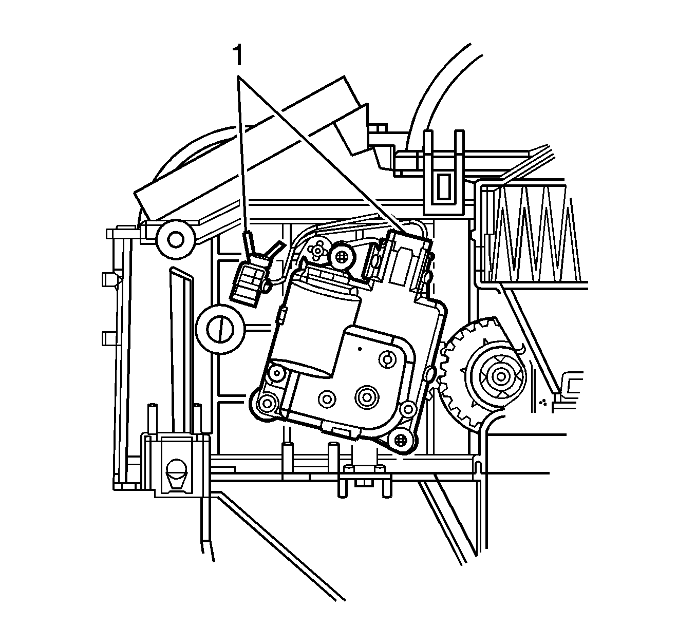
- Locate the air temperature actuator (1).
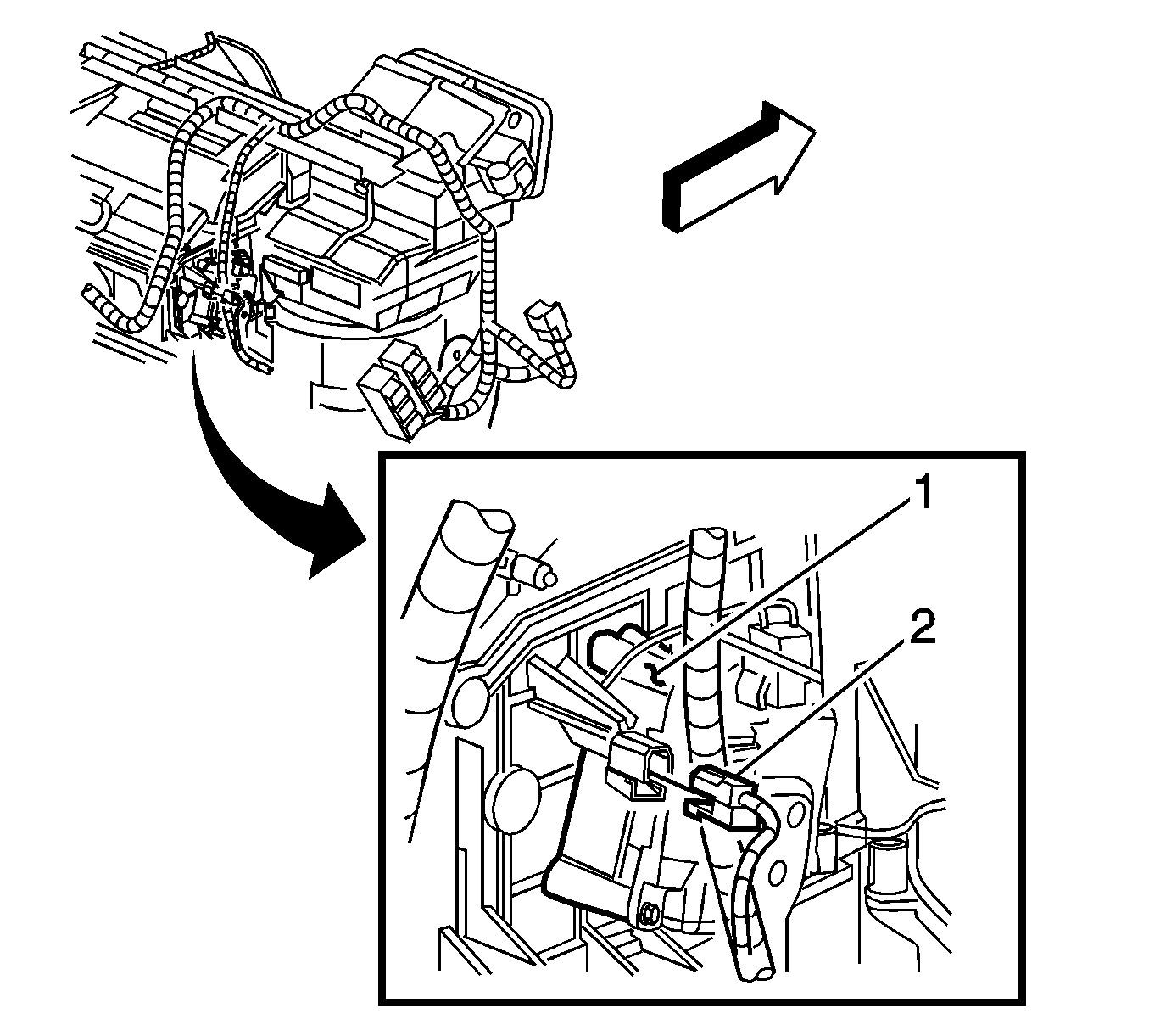
- Disconnect the right side air temperature actuator electrical connector (2).
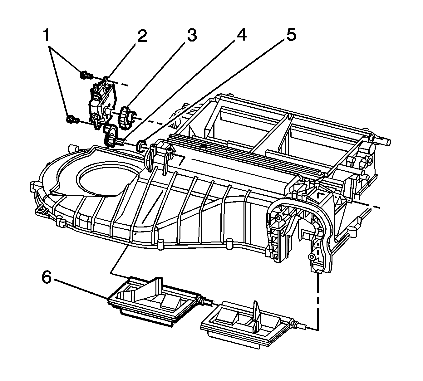
- Remove the right side air temperature actuator bolts/screws (1).
- Remove the right side air temperature actuator (2).
- Remove the right side air temperature actuator levers (3, 4), if necessary.
Installation Procedure
- Install the right side air temperature actuator levers, if necessary.
- Check and correct the engagement between the actuator levers (1, 2).
- Install the right side air temperature actuator (2).
- Install the right side air temperature actuator bolts/screws.
- Connect the right side air temperature actuator electrical connector (2).
- Ensure that the clip (1) on the connector is fully inserted to the holder on the case.
- Install the I/P compartment. Refer to Instrument Panel Compartment Assembly, Door, Striker, and Latch Replacement in Instrument Panel, Gages, and Console.
- Re-calibrate the actuators. Refer to Actuator Recalibration .
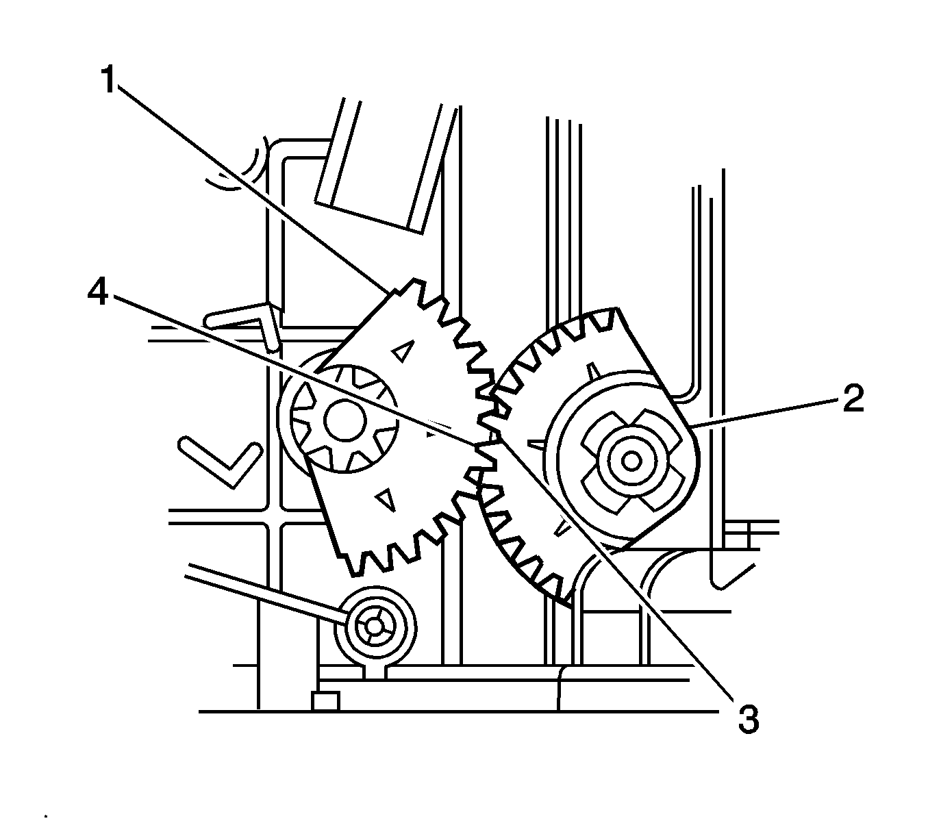
Important: The actuator lever (2) can only be inserted into the door one way.
| 2.1. | Install the actuator lever (2). |
| 2.2. | Align the primary tooth (4) of the actuator lever (1) with the gap (3) in the actuator lever (2). |
Notice: Refer to Fastener Notice in the Preface section.
Tighten
Tighten the bolts/screws to 1.2 N·m
(11 lb in).