| Table 1: | Digital Radio Receiver (U2K) |
| Table 2: | Radio C1 |
| Table 3: | Radio (w/U2K) C2 |
| Table 4: | Rear Seat Audio (RSA) Control |
| Table 5: | Rear Video/Audio/HVAC Module - C1 |
| Table 6: | Rear Video/Audio/HVAC Module - C2 |
| Table 7: | Rear Video/Audio/HVAC Module - C3 |
| Table 8: | Speaker - LF Door |
| Table 9: | Speaker - LR Liftgate |
| Table 10: | Speaker - RF Door |
| Table 11: | Speaker - RR Liftgate |
| Table 12: | Video Disc Player |
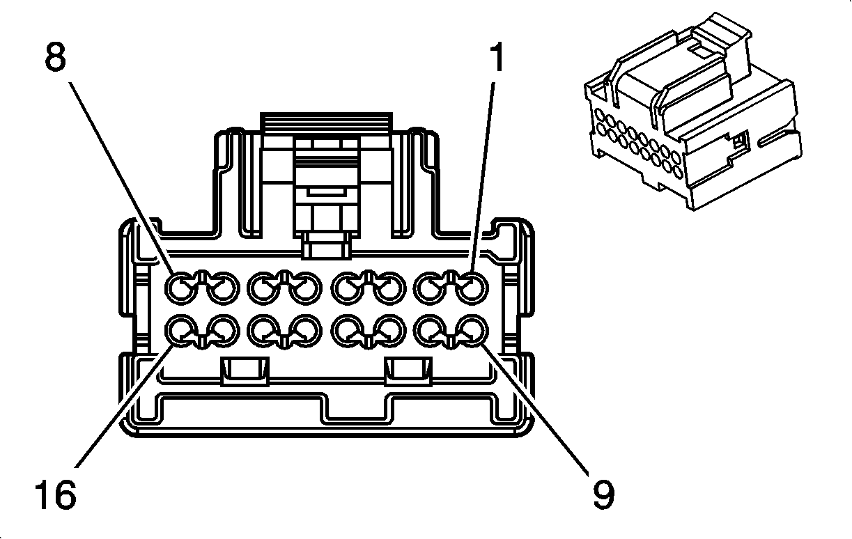
| |||||||
|---|---|---|---|---|---|---|---|
Connector Part Information |
| ||||||
Pin | Wire Color | Circuit No. | Function | ||||
1 | -- | -- | Not Used | ||||
2 | BRN | 367 | Remote Radio Left Audio Signal | ||||
3 | DK GRN | 368 | Remote Radio Right Audio Signal | ||||
4-8 | -- | -- | Not Used | ||||
9 | BLK | 351 | Ground | ||||
10 | BLK/WHT | 372 | Audio Common | ||||
11 | BARE | 813 | Drain Wire | ||||
12-14 | -- | -- | Not Used | ||||
15 | DK BLU | 2272 | Amplifier Class 2 Data | ||||
16 | ORN | 2440 | Battery Positive Voltage | ||||
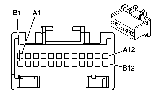
| |||||||
|---|---|---|---|---|---|---|---|
Connector Part Information |
| ||||||
Pin | Wire Color | Circuit No. | Function | ||||
A1 | ORN | 1044 | Class 2 Serial Data | ||||
A2 | -- | -- | Not Used | ||||
A3 | PPL | 493 | Rear Seat Audio Enable Signal (w/o U32) | ||||
A4-A5 | -- | -- | Not Used | ||||
A6 | PNK | 314 | Radio On Signal | ||||
A7 | DK BLU | 1796 | Steering Wheel Controls Signal | ||||
A8 | TAN | 201 | Left Front Speaker Output (+) | ||||
A9 | GRY | 118 | Left Front Speaker Output (-) | ||||
A10 | LT BLU | 115 | Right Rear Speaker Output (-) | ||||
A11 | DK BLU | 46 | Right Rear Speaker Output (+) | ||||
A12 | BLK/WHT | 351 | Ground | ||||
B1 | ORN | 640 | Battery Positive Voltage | ||||
B2 | -- | -- | Not Used | ||||
B3 | PPL | 493 | Rear Seat Audio Enable Signal (with U32) | ||||
B4 | BRN/WHT | 230 | Instrument Panel Lamps Dimming Control | ||||
B5 | BLK/WHT | 351 | Ground | ||||
B6 | -- | -- | Not Used | ||||
B7 | LT GRN | 1011 | Remote Radio Control Signal | ||||
B8 | BRN | 199 | Left Rear Speaker Output (+) | ||||
B9 | YEL | 116 | Left Rear Speaker Output (-) | ||||
B10 | DK GRN | 117 | Right Front Speaker Output (-) | ||||
B11 | LT GRN | 200 | Right Front Speaker Output (+) | ||||
B12 | GRY/BLK | 308 | Step Dim Signal | ||||
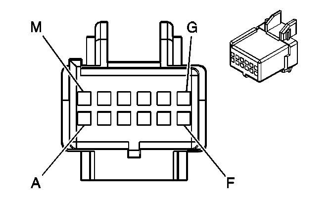
| |||||||
|---|---|---|---|---|---|---|---|
Connector Part Information |
| ||||||
Pin | Wire Color | Circuit No. | Function | ||||
A-F | -- | -- | Not Used | ||||
G | PPL | 1807 | Class 2 Serial Data (U32) | ||||
H | DK GRN | 368 | Remote Radio Right Audio Signal | ||||
DK GRN | 368 | Remote Radio Right Audio Signal (U32) | |||||
J | BRN | 367 | Remote Radio Left Audio Signal | ||||
BRN | 367 | Remote Radio Left Audio Signal (U32) | |||||
K | BLK/WHT | 372 | Remote Radio Audio Output (-) | ||||
BLK/WHT | 372 | Remote Radio Audio Output (-) (U32) | |||||
L | BLK/WHT | 372 | Remote Radio Audio Output (-) (UE1) | ||||
M | BRN/WHT | 367 | Remote Radio Left Audio Signal (UE1) | ||||
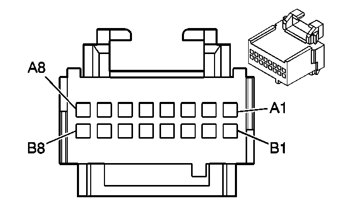
| |||||||
|---|---|---|---|---|---|---|---|
Connector Part Information |
| ||||||
Pin | Wire Color | Circuit No. | Function | ||||
A1 | LT BLU | 115 | Right Rear Speaker Output (-) | ||||
A2 | DK BLU | 46 | Left Rear Speaker Output (+) | ||||
A3 | YEL | 116 | Left Rear Speaker Output (-) | ||||
A4 | BRN | 199 | Right Rear Speaker Output (+) | ||||
A5 | LT GRN | 1011 | Remote Radio Control Signal | ||||
A6 | GRY | 8 | Instrument Panel Lamp Supply Voltage - 1 | ||||
A7 | -- | -- | Not Used | ||||
A8 | PNK | 314 | Radio ON Signal | ||||
B1 | LT BLU | 115 | Right Rear Speaker Output (-) | ||||
B2 | DK BLU | 46 | Right Rear Speaker Output (+) | ||||
B3 | YEL | 116 | Left Rear Speaker Output (-) | ||||
B4 | BRN | 199 | Left Rear Speaker Output (+) | ||||
B5 | PPL | 493 | Rear Seat Audio Enable Signal | ||||
B6 | BLK/WHT | 351 | Ground | ||||
B7 | -- | -- | Not Used | ||||
B8 | GRY/BLK | 308 | Step Dim Signal | ||||
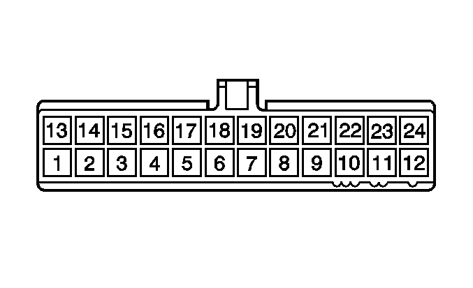
| |||||||
|---|---|---|---|---|---|---|---|
Connector Part Information |
| ||||||
Pin | Wire Color | Circuit No. | Function | ||||
1-7 | -- | -- | Not Used | ||||
8 | BLK/WHT | 351 | Ground | ||||
9 | -- | -- | Not Used | ||||
10 | PPL | 493 | Rear Seat Audio Enable Signal | ||||
11 | DK BLU | 46 | Right Rear Speaker Output (+) | ||||
12 | LT BLU | 115 | Right Rear Speaker Output (-) | ||||
13 | GRY/BLK | 308 | Step Dim Signal | ||||
14 | BRN | 199 | Left Rear Speaker Output (+) | ||||
15 | YEL | 116 | Left Rear Speaker Output (-) | ||||
16 | DK BLU | 46 | Right Rear Speaker Output (+) | ||||
17 | LT BLU | 115 | Right Rear Speaker Output (-) | ||||
18 | BRN | 199 | Left Rear Speaker Output (+) | ||||
19 | YEL | 116 | Left Rear Speaker Output (-) | ||||
20 | -- | -- | Not Used | ||||
21 | GRY | 8 | Instrument Panel Lamp Supply Voltage - 1 | ||||
22 | BLK | 2614 | Auxiliary Air Temperature Door Control | ||||
23 | LT BLU | 733 | Auxiliary Air Temperature Door Position Signal | ||||
24 | -- | -- | Not Used | ||||
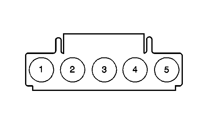
| |||||||
|---|---|---|---|---|---|---|---|
Connector Part Information |
| ||||||
Pin | Wire Color | Circuit No. | Function | ||||
1 | ORN | 1052 | Auxiliary Blower Motor High Speed Relay Control | ||||
2 | LT BLU | 1072 | Auxiliary Blower Motor Medium Speed Control | ||||
3 | YEL | 1176 | Auxiliary Blower Motor Low Speed Control | ||||
4 | ORN | 1923 | Auxiliary HVAC Switch Supply Voltage | ||||
5 | -- | -- | Not Used | ||||
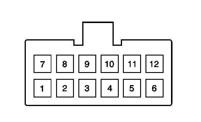
| |||||||
|---|---|---|---|---|---|---|---|
Connector Part Information |
| ||||||
Pin | Wire Color | Circuit No. | Function | ||||
1 | -- | -- | Not Used | ||||
2 | BLK/WHT | 9372 | DVD Audio Signal (-) | ||||
3 | DK GRN/WHT | 9368 | DVD Audio Right Signal (+) | ||||
4 | BRN/WHT | 9367 | DVD Audio Left Signal (+) | ||||
5 | RED | 9352 | DVD Infrared Command Serial Data Signal | ||||
6 | PPL/WHT | 9724 | Display Dimming Signal | ||||
7 | -- | -- | Not Used | ||||
8 | TAN | 9351 | Video Signal (-) | ||||
9 | PPL | 9350 | Video Signal (+) | ||||
10 | BLK | 9150 | Rear Video/Audio/HVAC Module Ground | ||||
11 | RED/WHT | 9136 | Rear Video/Audio/HVAC Module Supply Voltage | ||||
12 | YEL | 710 | Class 2 Serial Data | ||||
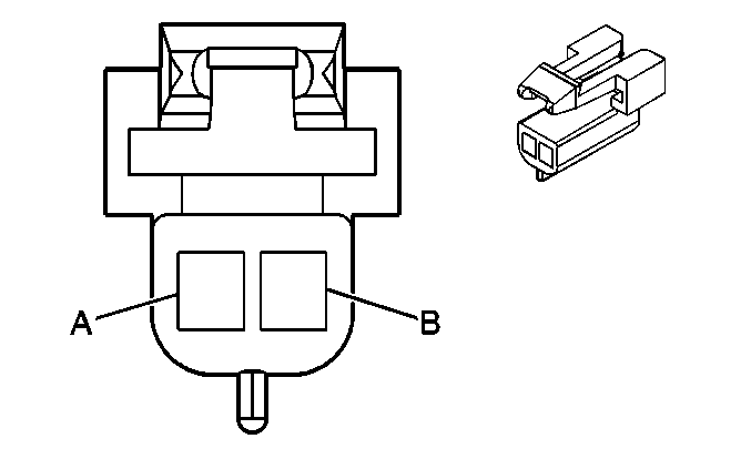
| |||||||
|---|---|---|---|---|---|---|---|
Connector Part Information |
| ||||||
Pin | Wire Color | Circuit No. | Function | ||||
A | GRY | 118 | Left Front Speaker Output (-) | ||||
B | TAN | 201 | Left Front Speaker Output (+) | ||||

| |||||||
|---|---|---|---|---|---|---|---|
Connector Part Information |
| ||||||
Pin | Wire Color | Circuit No. | Function | ||||
A | YEL | 116 | Left Rear Speaker Output (-) | ||||
B | BRN | 199 | Left Rear Speaker Output (+) | ||||

| |||||||
|---|---|---|---|---|---|---|---|
Connector Part Information |
| ||||||
Pin | Wire Color | Circuit No. | Function | ||||
A | DK GRN | 117 | Right Front Speaker Output (-) | ||||
B | LT GRN | 200 | Right Front Speaker Output (+) | ||||

| |||||||
|---|---|---|---|---|---|---|---|
Connector Part Information |
| ||||||
Pin | Wire Color | Circuit No. | Function | ||||
A | LT BLU | 115 | Right Rear Speaker Output (-) | ||||
B | DK BLU | 46 | Right Rear Speaker Output (+) | ||||

| |||||||
|---|---|---|---|---|---|---|---|
Connector Part Information |
| ||||||
Pin | Wire Color | Circuit No. | Function | ||||
A1 | ORN | 2440 | Battery Positive Voltage | ||||
A2 | -- | -- | Not Used | ||||
A3 | PPL/WHT | 9724 | Display Dimming Signal | ||||
A4 | -- | -- | Not Used | ||||
A5 | BRN/WHT | 9367 | DVD Audio Left Signal (+) | ||||
A6 | DK GRN/WHT | 9368 | DVD Audio Right Signal (+) | ||||
A7 | DK BLU/WHT | 9372 | DVD Audio Signal (-) | ||||
A8 | BARE | 9514/9514 | Drain Wire | ||||
A9 | RED | 9352 | DVD Infrared Command Serial Data Signal | ||||
A10-A12 | -- | -- | Not Used | ||||
B1 | BRN | 367 | Remote Radio Left Audio Signal | ||||
B2 | DK GRN | 368 | Remote Radio Right Audio Signal | ||||
B3 | BLK/WHT | 372 | Remote Radio Audio Output (-) | ||||
B4 | BARE | 1574 | Drain Wire | ||||
B5 | RED/WHT | 9136 | Rear Video/Audio/HVAC Module Supply Voltage | ||||
B6 | PPL | 9150 | Rear Video/Audio/HVAC Module Ground | ||||
B7 | PPL | 1807 | Class 2 Serial Data | ||||
B8 | YEL | 710 | Class 2 Serial Data | ||||
B9 | BARE | 9514 | Drain Wire | ||||
BARE | 9514 | Drain Wire | |||||
B10 | TAN | 9351 | Video Signal (-) | ||||
B11 | PPL | 9350 | Video Signal (+) | ||||
B12 | BLK/WHT | 351 | Ground | ||||
