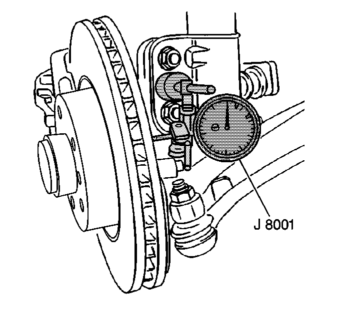
A vehicle that has rotors with excessive lateral runout
can exhibit brake pulsation or a shudder condition during braking.
Tools Required
J 8001 Dial Indicator Set
- Raise and support the vehicle. Refer to
Lifting and Jacking the Vehicle
in General Information.
Important: Before performing the brake rotor lateral runout check, inspect the
wheel bearing/hub for excessive looseness and excessive lateral runout.
- Refer to
Wheel Bearings Diagnosis - Sealed
in Suspension General Diagnosis.
- Remove the tire and wheel.
- Install and tighten the wheel nuts in order to retain the rotor.

- Fasten the J 8001
to the knuckle. Ensure that the J 8001
button contacts the rotor surface about 13 mm
(0.500 in) from the rotor outer edge.
- Set the J 8001
to
zero.
- Rotate the rotor one complete revolution. Inspect the J 8001
.
| • | If the runout exceeds 0.080 mm (0.003 in), go to
Step 8. |
| • | If the runout is less than 0.080 mm (0.003 in),
go to Step 13. |
- Mark the relationship of the rotor to the hub.
Notice: Whenever the brake rotor has been separated from the wheel bearing flange,
clean any rust or foreign material from the mating surface of the rotor and
flange with the J 42450 hub cleaning kit. Failure to do
this may result in increased lateral runout of the rotor and brake pulsation.
- Remove the brake rotor. Refer to
Front Brake Rotor Replacement
or
Rear Brake Rotor Replacement
.
- Clean any rust or foreign material from the mating surface of
the rotor and the hub.
- Install the brake rotor on the hub, one or two bolt positions
from the rotor's original position. Repeat Steps 5 through 8.
If the runout still exceeds 0.080 mm (0.003 in), refinish
or replace the rotor as necessary.
For the front rotor refinishing procedure, refer to
Brake Rotor Refinishing
.
- Remove the wheel nuts securing the rotor to the hub.
- Install the tire and wheel.
- Lower the vehicle.

