DTC P0742 2.2 L
Circuit Description
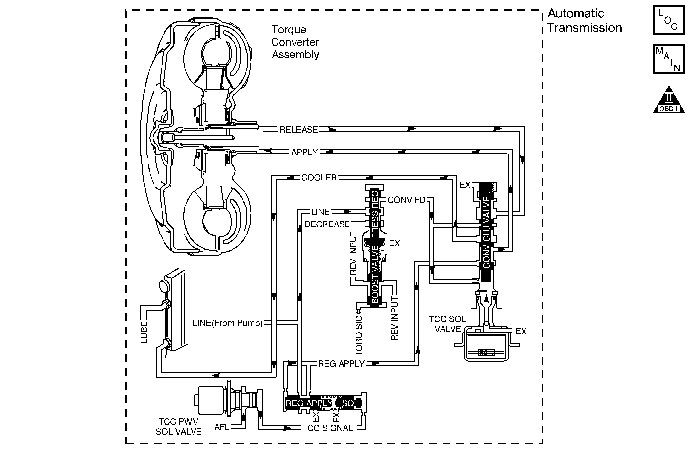
The torque converter clutch (TCC) solenoid valve is a normally-open exhaust valve that is used with the torque converter clutch pulse width modulation (TCC PWM) solenoid valve in order to control fluid acting on the converter clutch apply valve. The TCC solenoid valve attaches to the transmission case assembly extending into the pump cover. When grounded, energized, by the powertrain control module (PCM), the TCC solenoid valve stops converter signal oil from exhausting. This causes converter signal oil pressure to increase and move the converter clutch apply valve against spring force and into the apply position. In this position, release fluid is open to an exhaust port and converter feed fluid fills the apply fluid circuit. The converter feed fluid applies the TCC. When the PCM no longer provides a ground path, the TCC solenoid valve de-energizes and apply fluid exhausts, releasing the TCC.
When the PCM detects low torque converter slip when the PCM commands the TCC OFF, then DTC P0742 sets. DTC P0742 is a type B DTC.
Conditions for Running the DTC
| • | No MAP sensor DTCs P0107 or P0108. |
| • | No TP sensor DTCs P0122 or P0123. |
| • | No VSS assembly DTCs P0502 or P0503. |
| • | No TCC solenoid valve DTC P0740. |
| • | No TFP manual valve position switch DTC P1810. |
| • | No TCC PWM solenoid valve DTC P1860. |
| • | The TP angle is 15-60 percent. |
| • | The engine speed is greater than 450 RPM for 5 seconds. |
| • | The engine is not in fuel cutoff. |
| • | The engine torque is 54 N·m (40 lb ft) or greater. |
| • | The engine vacuum is 0-105 kPa (0-15 psi). |
| • | The engine speed is 1,000-3,000 RPM. |
| • | The speed ratio is 0.65-1.25, the speed ratio is engine speed divided by output speed. |
| • | The vehicle speed is 32-113 km/h (20-70 mph). |
| • | The commanded gear is not 1st. |
| • | The transmission gear range is D4. |
| • | The transmission gear range does not change within 6 seconds. |
| • | The TCC is commanded OFF. |
Conditions for Setting the DTC
DTC P0742 sets if the following condition occurs twice during the same trip.
The TCC slip speed is -20 to +30 RPM for greater than 5 seconds.
Action Taken When the DTC Sets
| • | The PCM illuminates the malfunction indicator lamp (MIL) during the second consecutive trip in which the Conditions for Setting the DTC are met. |
| • | The PCM freezes transmission adapt functions. |
| • | The PCM records the operating conditions when the Conditions for Setting the DTC are met. The PCM stores this information as Freeze Frame and Failure Records. |
| • | The PCM stores DTC P0742 in PCM history during the second consecutive trip in which the Conditions for Setting the DTC are met. |
Conditions for Clearing the MIL/DTC
| • | The PCM turns OFF the MIL during the third consecutive trip in
which the diagnostic test runs and passes. |
| • | A scan tool can clear the MIL/DTC. |
| • | The PCM clears the DTC from PCM history if the vehicle completes
40 warm-up cycles without an emission-related
diagnostic fault occurring. |
| • | The PCM cancels the DTC default actions when the ignition switch
is OFF long enough in order to power down the PCM. |
Diagnostic Aids
The TCC fluid hydraulically applies the TCC, possibly causing an engine stall, under the following conditions:
| • | The TCC is hydraulically stuck ON |
| • | The parking brake is applied |
| • | Any gear range is selected |
Test Description
The number below refers to the step number on the diagnostic table.
-
This step tests the mechanical state of the TCC. When the PCM commands the TCC solenoid valve OFF, the slip speed should increase.
DTC P0742 (2.2 L)
Step
| Action
| Value(s)
| Yes
| No
|
1
| Did you perform the Powertrain Diagnostic System Check?
| --
| Go to
Step
2
| Go to
Diagnostic System Check - Engine Controls
in Engine Controls - 2.2 L
|
2
|
- Install a scan tool.
- Turn ON the ignition, with the engine OFF.
Important: Before clearing the DTC, use the scan tool in order to record the Freeze Frame and Failure Records. Using the Clear Info function erases the Freeze Frame and Failure Records from the PCM.
- Record the DTC Freeze Frame and Failure Records.
- Clear the DTC.
- Drive the vehicle in the D4 drive range in second, third or fourth gear under steady acceleration, with a TP angle at 20 percent.
While the scan tool TCC Enable status is No, does the scan tool display
a TCC Slip Speed within the specified range?
| -20 to +30 RPM
| Go to
Step 3
| Go to Diagnostic Aids
|
3
| The TCC is hydraulically
stuck ON. Inspect for the following conditions:
| • | A clogged exhaust orifice in the TCC solenoid valve. |
| • | The converter clutch apply valve is stuck in the apply position. |
| • | A misaligned or damaged valve body gasket. |
| • | A restricted release passage. |
| • | A restricted transmission cooler line. |
Did you find and correct the condition?
| --
| Go to
Step 4
| --
|
4
| Perform the following procedure in order to verify the repair:
- Select DTC.
- Select Clear Info.
- Drive the vehicle in D4 under the following conditions:
Hold the throttle at 25% and accelerate to 88 km/h (55 mph). Ensure that the scan tool TCC Slip Speed is 100 to 2,000 RPM for 4 seconds, with the TCC OFF.
- Select Specific DTC.
- Enter DTC P0742.
Has the test run and passed?
| --
| System OK
| Go to
Step 1
|
DTC P0742 4.3 L
Circuit Description
The torque converter clutch (TCC) solenoid valve is a normally-open exhaust valve that is used with the torque converter clutch pulse width modulation (TCC PWM) solenoid valve in order to control fluid acting on the converter clutch apply valve. The TCC solenoid valve attaches to the transmission case assembly extending into the pump cover. When grounded, energized, by the powertrain control module (PCM), the TCC solenoid valve stops converter signal oil from exhausting. This causes converter signal oil pressure to increase and move the converter clutch apply valve against spring force and into the apply position. In this position, release fluid is open to an exhaust port and converter feed fluid fills the apply fluid circuit. The converter feed fluid applies the TCC. When the PCM no longer provides a ground path, the TCC solenoid valve de-energizes and apply fluid exhausts, releasing the TCC.
When the PCM detects low TCC slip when the TCC is commanded OFF, then DTC P0742 sets. DTC P0742 is a type B DTC.
Conditions for Running the DTC
| • | No TP sensor DTCs P0122 or P0123. |
| • | No VSS assembly DTCs P0502 or P0503. |
| • | No TCC solenoid valve DTC P0740. |
| • | No TFP manual valve position switch DTC P1810. |
| • | No TCC PWM solenoid valve DTC P1860. |
| • | The TP angle is 17-45 percent. |
| • | The engine speed is greater than 300 RPM for 6 seconds. |
| • | The engine is not in fuel cutoff. |
| • | The TFT is between 20-130°C (68-266°F). |
| • | The engine vacuum is 0-105 kPa (0-15 psi). |
| • | The engine torque is 68-542 N·m (50-400 lb ft). |
| • | The engine speed is 1,000-3,000 RPM. |
| • | The speed ratio is 0.64 to 1.35. |
| • | The vehicle speed is 24-80 km/h (15-50 mph). |
| • | The gear range does not change within 5 seconds. |
| • | The commanded gear is not 1st. |
| • | The TCC is commanded OFF. |
Conditions for Setting the DTC
DTC P0742 sets if the following condition occurs twice.
The TCC slip speed is -20 to +20 RPM for 5 seconds.
Action Taken When the DTC Sets
| • | The PCM illuminates the malfunction indicator lamp (MIL) during the second consecutive trip in which the Conditions for Setting the DTC are met. |
| • | The PCM freezes shift adapts from being updated. |
| • | The PCM records the operating conditions when the Conditions for Setting the DTC are met. The PCM stores this information as Freeze Frame and Failure Records. |
| • | The PCM stores DTC P0742 in PCM history during the second consecutive trip in which the Conditions for Setting the DTC are met. |
Conditions for Clearing the MIL/DTC
| • | The PCM turns OFF the MIL during the third consecutive trip in
which the diagnostic test runs and passes. |
| • | A scan tool can clear the MIL/DTC. |
| • | The PCM clears the DTC from PCM history if the vehicle completes
40 warm-up cycles without an emission-related
diagnostic fault occurring. |
| • | The PCM cancels the DTC default actions when the ignition switch
is OFF long enough in order to power down the PCM. |
Diagnostic Aids
The TCC fluid hydraulically applies the TCC, possibly causing an engine stall, under the following conditions:
| • | The TCC is hydraulically stuck ON. |
| • | The parking brake is applied. |
| • | Any gear range is selected. |
Test Description
The number below refers to the step number on the diagnostic table.
-
This step tests the hydraulic state of the TCC. When the PCM commands the TCC solenoid valve OFF, the slip speed should increase.
DTC P0742 (4.3 L)
Step
| Action
| Value(s)
| Yes
| No
|
1
| Did you perform the Powertrain Diagnostic System Check?
| --
| Go to
Step 2
| Go to
Diagnostic System Check - Engine Controls
in Engine Controls - 4.3 L
|
2
|
- Install a scan tool.
- Turn ON the ignition, with the engine OFF.
Important: Before clearing the DTC, use the scan tool in order to record the Freeze Frame and Failure Records. Using the Clear Info. function erases the Freeze Frame and Failure Records from the PCM.
- Record the DTC Freeze Frame and Failure Records.
- Clear the DTC.
- Drive the vehicle in the D4 drive range in second, third, or fourth gear under steady acceleration, with a TP angle at 20%.
While the scan tool TCC Enable status is NO, does the scan tool display a TCC Slip Speed within the specified range?
| -20 to +20 RPM
| Go to
Step 3
| Go to Diagnostic Aids
|
3
| The TCC is hydraulically stuck ON. Inspect for the following:
| • | Clogged exhaust orifice in the TCC solenoid valve. |
| • | Converter clutch apply valve stuck in the apply position. |
| • | Misaligned or damaged valve body gasket. |
| • | Restricted release passage. |
| • | Restricted transmission cooler line. |
Did you find and correct the condition?
| --
| Go to
Step 4
| --
|
4
| Perform the following procedure in order to verify the repair:
- Select DTC.
- Select Clear Info.
- Drive the vehicle in D4 with the TCC OFF and the throttle above 17%. Ensure that the scan tool TCC Slip Speed is 100-2,000 RPM for 5 seconds.
- Select Specific DTC.
- Enter DTC P0742.
Has the test run and passed?
| --
| System OK
| Go to
Step 1
|
