Accelerator Pedal Position (APP) Sensor
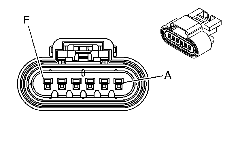
Connector Part Information
|
Terminal Part Information
|
Pin | Wire Color | Circuit No. | Function |
|---|---|---|---|
A | 0.35 PU | 1272 | Low Reference |
B | 0.35 L-BU | 1162 | APP Sensor 2 Signal |
C | 0.35 TN | 1274 | 5-Volt Reference |
D | 0.35 WH/BK | 1164 | 5-Volt Reference |
E | 0.35 D-BU | 1161 | APP Sensor 1 Signal |
F | 0.35 BN | 1271 | Low Reference |
Camshaft Actuator Solenoid (6.0L/6.2L)
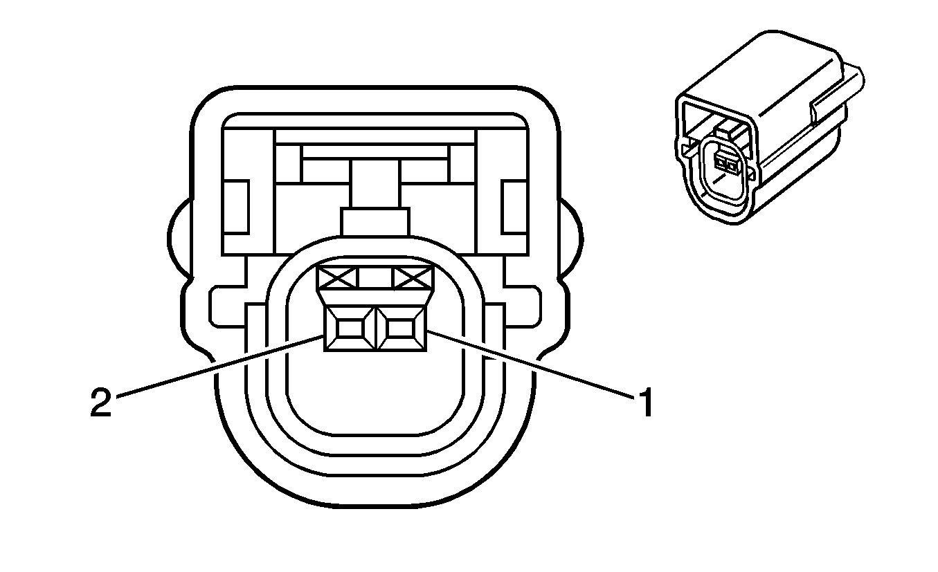
Connector Part Information
|
Terminal Part Information
|
Pin | Wire Color | Circuit No. | Function |
|---|---|---|---|
1 | 0.35 TN | 2199 | Low Reference |
2 | 0.35 PU | 5284 | Camshaft Actuator Solenoid Control |
Camshaft Position (CMP) Sensor
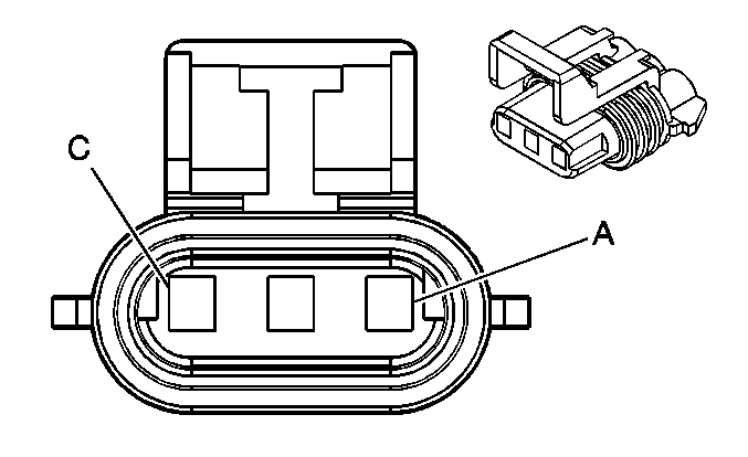
Connector Part Information
|
Terminal Part Information
|
Pin | Wire Color | Circuit No. | Function |
|---|---|---|---|
A | 0.35 D-BU | 6259 | 5-Volt Reference |
B | 0.35 BN | 6266 | Low Reference |
C | 0.35 D-BU/WH | 6265 | Camshaft CAM W Signal |
Crankshaft Position (CKP) Sensor
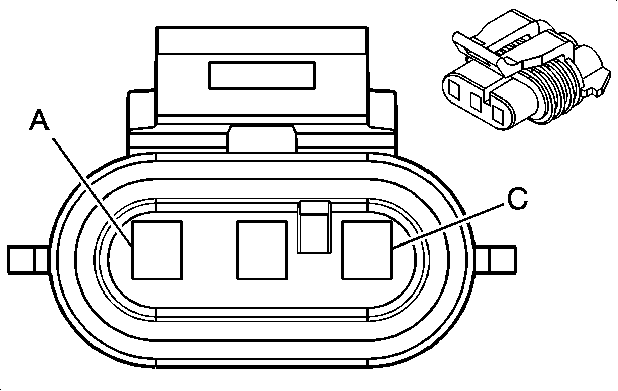
Connector Part Information
|
Terminal Part Information
|
Pin | Wire Color | Circuit No. | Function |
|---|---|---|---|
A | 0.35 WH/BK | 6271 | CKP Sensor Signal |
B | 0.35 GY/BK | 6272 | Low Reference |
C | 0.35 PU/WH | 6270 | 5-Volt Reference |
Engine Coolant Temperature (ECT) Sensor
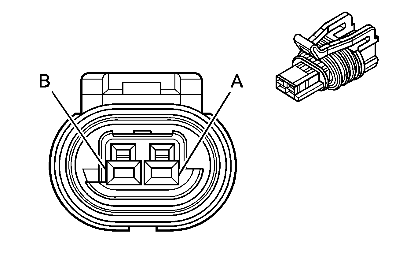
Connector Part Information
|
Terminal Part Information
|
Pin | Wire Color | Circuit No. | Function |
|---|---|---|---|
A | 0.5 TN | 2761 | Low Reference |
B | 0.5 YE | 410 | ECT Sensor Signal |
Evaporative Emission (EVAP) Canister Purge Solenoid Valve
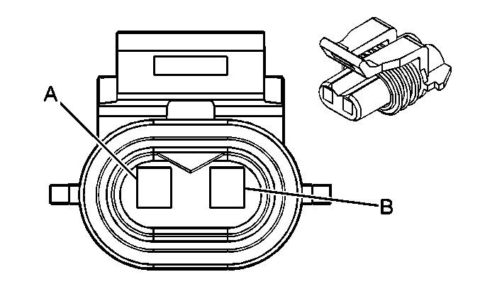
Connector Part Information
|
Terminal Part Information
|
Pin | Wire Color | Circuit No. | Function |
|---|---|---|---|
A | 0.5 PK | 1839 | Ignition 1 Voltage |
B | 0.5 D-GN/WH | 428 | EVAP Canister Purge Solenoid Control |
Evaporative Emission (EVAP) Canister Vent Solenoid Valve
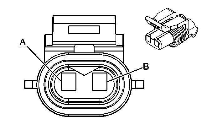
Connector Part Information
|
Terminal Part Information
|
Pin | Wire Color | Circuit No. | Function |
|---|---|---|---|
A | 0.5 WH | 1310 | EVAP Canister Vent Solenoid Control |
B | 0.5 RD/WH | 1840 | Battery Positive Voltage |
Fuel Injector 1
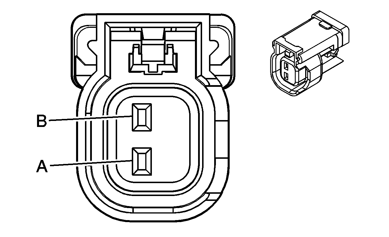
Connector Part Information
|
Terminal Part Information
|
Pin | Wire Color | Circuit No. | Function |
|---|---|---|---|
A | 0.8 PK/BK | 1039 | Ignition 1 Voltage |
B | 0.5 TN | 1744 | Fuel Injector 1 Control |
Fuel Injector 2

Connector Part Information
|
Terminal Part Information
|
Pin | Wire Color | Circuit No. | Function |
|---|---|---|---|
A | 0.8 PK | 1239 | Ignition 1 Voltage |
B | 0.5 L-GN/BK | 1745 | Fuel Injector 2 Control |
Fuel Injector 3

Connector Part Information
|
Terminal Part Information
|
Pin | Wire Color | Circuit No. | Function |
|---|---|---|---|
A | 0.8 PK/BK | 1039 | Ignition 1 Voltage |
B | 0.5 PK/BK | 1746 | Fuel Injector 3 Control |
Fuel Injector 4

Connector Part Information
|
Terminal Part Information
|
Pin | Wire Color | Circuit No. | Function |
|---|---|---|---|
A | 0.8 PK | 1239 | Ignition 1 Voltage |
B | 0.5 L-BU/BK | 844 | Fuel Injector 4 Control |
Fuel Injector 5

Connector Part Information
|
Terminal Part Information
|
Pin | Wire Color | Circuit No. | Function |
|---|---|---|---|
A | 0.8 PK | 1039 | Ignition 1 Voltage |
B | 0.5 TN/WH | 845 | Fuel Injector 5 Control |
Fuel Injector 6

Connector Part Information
|
Terminal Part Information
|
Pin | Wire Color | Circuit No. | Function |
|---|---|---|---|
A | 0.8 PK/WH | 1239 | Ignition 1 Voltage |
B | 0.5 YE/BK | 846 | Fuel Injector 6 Control |
Fuel Injector 7

Connector Part Information
|
Terminal Part Information
|
Pin | Wire Color | Circuit No. | Function |
|---|---|---|---|
A | 0.8 PK | 1039 | Ignition 1 Voltage |
B | 0.5 OG/BK | 877 | Fuel Injector 7 Control |
Fuel Injector 8

Connector Part Information
|
Terminal Part Information
|
Pin | Wire Color | Circuit No. | Function |
|---|---|---|---|
A | 0.8 PK/WH | 1239 | Ignition 1 Voltage |
B | 0.5 D-BU/WH | 878 | Fuel Injector 8 Control |
Fuel Line Pressure Sensor (-LMG/LY6/LC9)
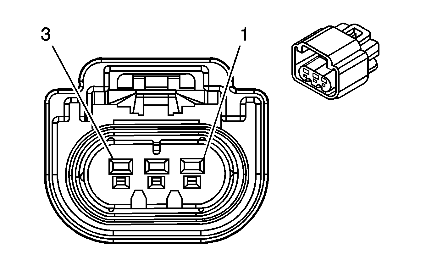
Connector Part Information
|
Terminal Part Information
|
Pin | Wire Color | Circuit No. | Function |
|---|---|---|---|
1 | 0.5 PU | 7446 | Fuel Line Pressure Sensor Signal |
2 | 0.5 GY | 7447 | Low Reference |
3 | 0.5 BN | 7445 | 5-Volt Reference |
Fuel Pump Relay - Secondary (LY6)
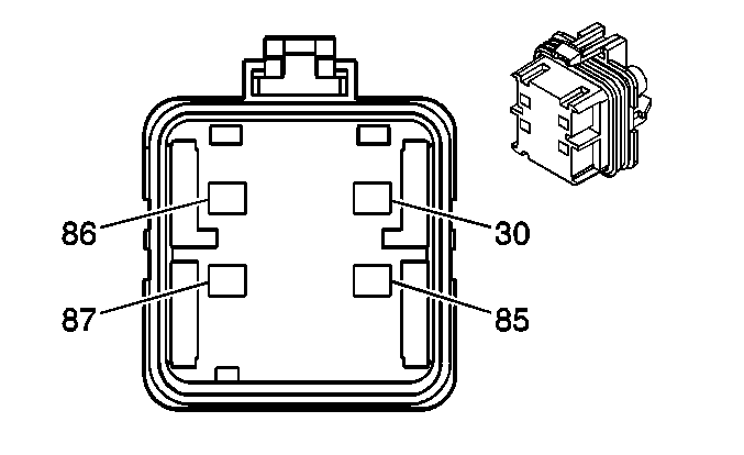
Connector Part Information
|
Terminal Part Information
|
Pin | Wire Color | Circuit No. | Function |
|---|---|---|---|
30 | 0.8 PK | 439 | Ignition 1 Voltage |
85 | 2.0 BK | 2150 | Ground |
86 | 0.5 TN | 1465 | Fuel Pump Relay Control - Secondary |
87 | 0.8 L-GN | 1058 | Fuel Balance Pump Supply Voltage |
Fuel System Control Module (-LMG/LY6/LC9)
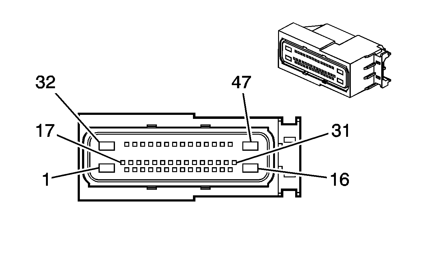
Connector Part Information
|
Terminal Part Information
|
Pin | Wire Color | Circuit No. | Function |
|---|---|---|---|
1 | 3.0 BK | 2150 | Ground |
2-4 | -- | -- | Not Used |
5 | 0.5 GY | 7447 | Low Reference |
6 | 0.5 TN | 2501 | High Speed GMLAN Serial Data Bus- |
7 | 0.5 TN/BK | 2500 | High Speed GMLAN Serial Data Bus+ |
8-9 | -- | -- | Not Used |
10 | 0.5 PU | 7446 | Fuel Line Pressure Sensor Signal |
11-12 | -- | -- | Not Used |
13 | 0.5 D-GN/WH | 465 | Fuel Pump Relay Control - Primary |
14 | -- | -- | Not Used |
15 | 0.5 PK | 439 | Ignition 1 Voltage |
16 | 3.0 PK | 1580 | Low Reference |
17 | 0.5 L-BU | 5986 | Serial Data Communication Enable |
18-20 | -- | -- | Not Used |
21 | 0.5 TN | 2501 | High Speed GMLAN Serial Data Bus- |
22 | 0.5 TN/BK | 2500 | High Speed GMLAN Serial Data Bus+ |
23-31 | -- | -- | Not Used |
32 | 3.0 RD/WH | 1940 | Battery Positive Voltage |
33-35 | -- | -- | Not Used |
36 | 0.5 BN | 7445 | 5-Volt Reference |
37-43 | -- | -- | Not Used |
44 | 0.5 GY | 7443 | Fuel System Control Module Shield Extension |
45-46 | -- | -- | Not Used |
47 | 3.0 GY | 120 | Fuel Pump Supply Voltage |
Fuel Tank Pressure (FTP) Sensor
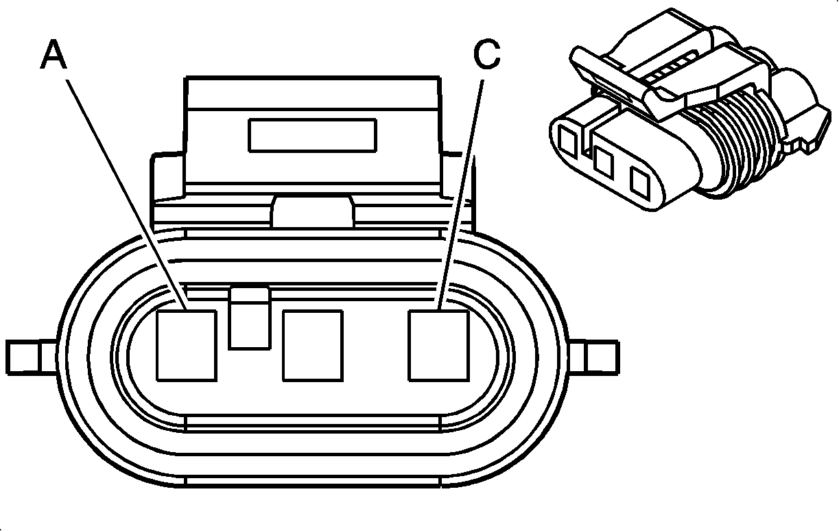
Connector Part Information
|
Terminal Part Information
|
Pin | Wire Color | Circuit No. | Function |
|---|---|---|---|
A | 0.5 TN/BK | 6049 | Low Reference |
B | 0.5 D-GN | 890 | Fuel Tank Pressure Sensor Signal |
C | 0.5 GY | 2709 | 5-Volt Reference |
Heated Oxygen Sensor (HO2S) Bank 1 Sensor 1
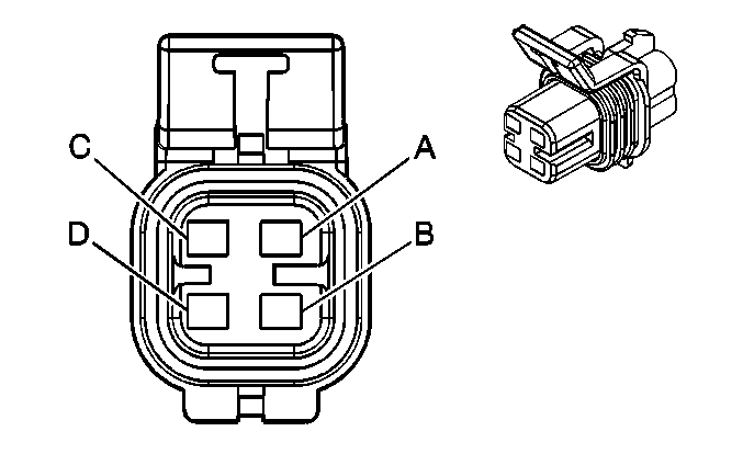
Connector Part Information
|
Terminal Part Information
|
Pin | Wire Color | Circuit No. | Function |
|---|---|---|---|
A | 0.85 TN | 1664 | HO2S Low Signal - Bank 1 Sensor 1 |
B | 0.85 PU/WH | 1665 | HO2S High Signal - Bank 1 Sensor 1 |
C | 0.85 GY/WH | 3113 | HO2S Heater Low Control - Bank 1 Sensor 1 |
D | 0.85 PK | 539 | Ignition 1 Voltage |
Heated Oxygen Sensor (HO2S) Bank 1 Sensor 2
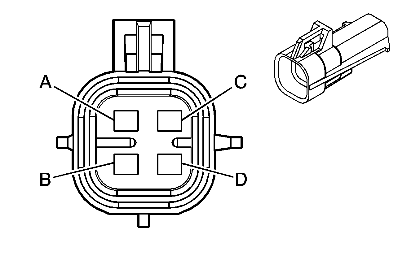
Connector Part Information
|
Terminal Part Information
|
Pin | Wire Color | Circuit No. | Function |
|---|---|---|---|
A | 0.8 TN/WH | 1669 | HO2S Low Signal - Bank 1 Sensor 2 |
B | 0.8 PU/WH | 1668 | HO2S High Signal - Bank 1 Sensor 2 |
C | 0.8 GY/WH | 3122 | HO2S Heater Low Control - Bank 1 Sensor 2 |
D | 0.8 PK/BK | 1539 | Ignition 1 Voltage |
Heated Oxygen Sensor (HO2S) Bank 2 Sensor 1

Connector Part Information
|
Terminal Part Information
|
Pin | Wire Color | Circuit No. | Function |
|---|---|---|---|
A | 0.85 TN | 1667 | HO2S Low Signal - Bank 2 Sensor 1 |
B | 0.85 PU | 1666 | HO2S High Signal - Bank 2 Sensor 1 |
C | 0.85 L-GN | 3212 | HO2S Heater Low Control - Bank 2 Sensor 1 |
D | 0.85 PK | 539 | Ignition 1 Voltage |
Heated Oxygen Sensor (HO2S) Bank 2 Sensor 2

Connector Part Information
|
Terminal Part Information
|
Pin | Wire Color | Circuit No. | Function |
|---|---|---|---|
A | 0.8 TN | 1671 | HO2S Low Signal - Bank 2 Sensor 2 |
B | 0.8 PU | 1670 | HO2S High Signal - Bank 2 Sensor 2 |
C | 0.8 OG/WH | 3223 | HO2S Heater Low Control - Bank 2 Sensor 2 (-LY6) |
0.8 BK | 550 | HO2S Heater Low Control - Bank 2 Sensor 2 (LY6) | |
D | 0.8 PK | 1539 | Ignition 1 Voltage |
Ignition Coil 1
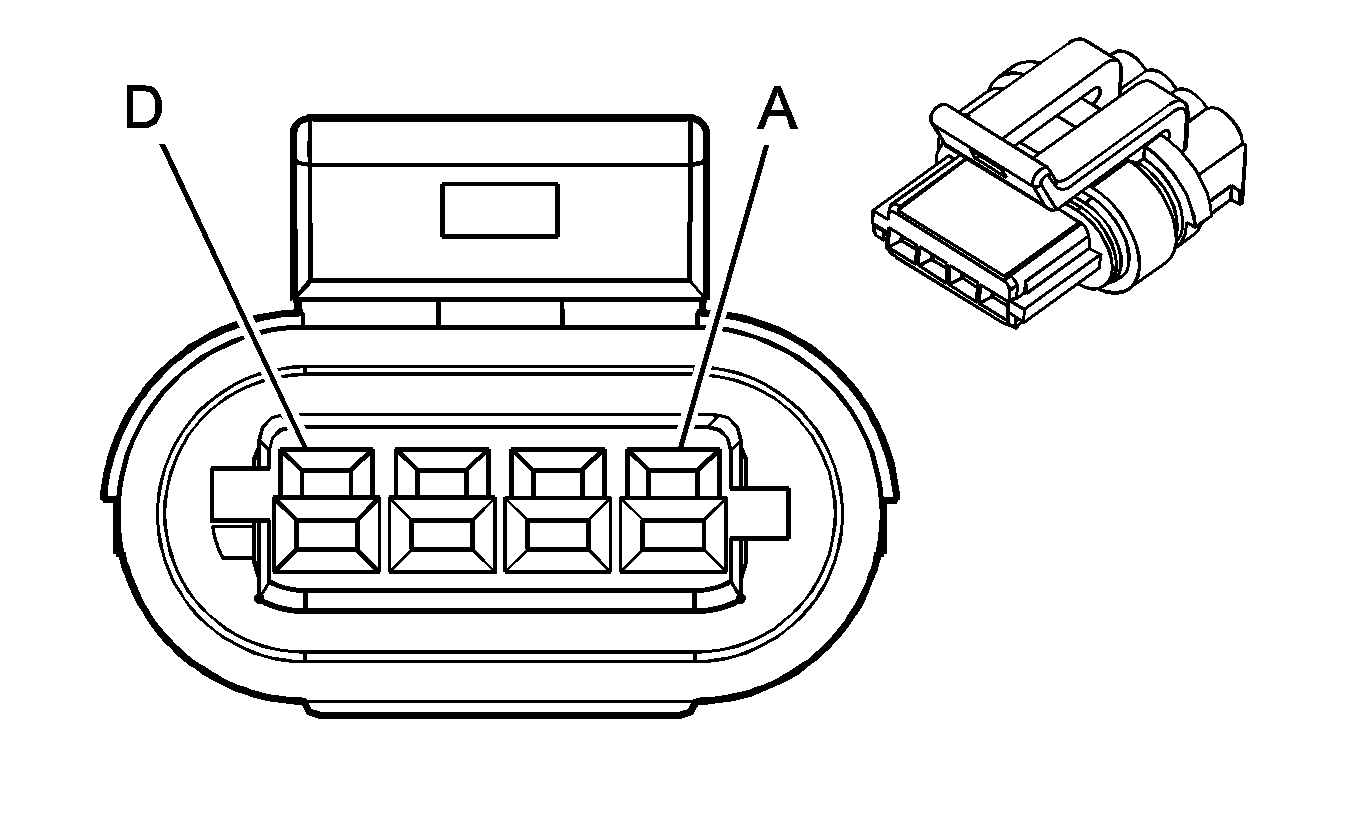
Connector Part Information
|
Terminal Part Information
|
Pin | Wire Color | Circuit No. | Function |
|---|---|---|---|
A | 0.8 BK | 350 | Ground |
B | 0.5 BN | 2129 | Low Reference |
C | 0.5 PU | 2121 | IC 1 Control |
D | 0.8 PK | 1039 | Ignition 1 Voltage |
Ignition Coil 2

Connector Part Information
|
Terminal Part Information
|
Pin | Wire Color | Circuit No. | Function |
|---|---|---|---|
A | 0.8 BK | 350 | Ground |
B | 0.5 BN | 2130 | Low Reference |
C | 0.5 OG | 2122 | IC 7 Control |
D | 0.8 PK | 1239 | Ignition 1 Voltage |
Ignition Coil 3

Connector Part Information
|
Terminal Part Information
|
Pin | Wire Color | Circuit No. | Function |
|---|---|---|---|
A | 0.8 BK | 350 | Ground |
B | 0.5 BN | 2129 | Low Reference |
C | 0.5 L-BU | 2123 | IC 3 Control |
D | 0.8 PK | 1039 | Ignition 1 Voltage |
Ignition Coil 4

Connector Part Information
|
Terminal Part Information
|
Pin | Wire Color | Circuit No. | Function |
|---|---|---|---|
A | 0.8 BK | 350 | Ground |
B | 0.5 BN | 2130 | Low Reference |
C | 0.5 D-GN | 2124 | IC 5 Control |
D | 0.8 PK | 1239 | Ignition 1 Voltage |
Ignition Coil 5

Connector Part Information
|
Terminal Part Information
|
Pin | Wire Color | Circuit No. | Function |
|---|---|---|---|
A | 0.8 BK | 350 | Ground |
B | 0.5 BN | 2129 | Low Reference |
C | 0.5 D-GN | 2125 | IC 5 Control |
D | 0.8 PK | 1039 | Ignition 1 Voltage |
Ignition Coil 6

Connector Part Information
|
Terminal Part Information
|
Pin | Wire Color | Circuit No. | Function |
|---|---|---|---|
A | 0.8 BK | 350 | Ground |
B | 0.5 BN | 2130 | Low Reference |
C | 0.5 L-BU | 2126 | IC 3 Control |
D | 0.8 PK | 1239 | Ignition 1 Voltage |
Ignition Coil 7

Connector Part Information
|
Terminal Part Information
|
Pin | Wire Color | Circuit No. | Function |
|---|---|---|---|
A | 0.8 BK | 350 | Ground |
B | 0.5 BN | 2129 | Low Reference |
C | 0.5 RD | 2127 | IC 7 Control |
D | 0.8 PK | 1039 | Ignition 1 Voltage |
Ignition Coil 8

Connector Part Information
|
Terminal Part Information
|
Pin | Wire Color | Circuit No. | Function |
|---|---|---|---|
A | 0.8 BK | 350 | Ground |
B | 0.5 BN | 2130 | Low Reference |
C | 0.5 PU | 2128 | IC 1 Control |
D | 0.8 PK | 1239 | Ignition 1 Voltage |
Knock Sensor (KS) - 1
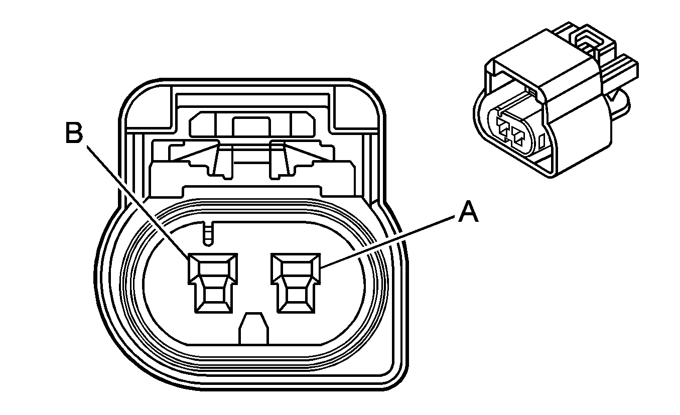
Connector Part Information
|
Terminal Part Information
|
Pin | Wire Color | Circuit No. | Function |
|---|---|---|---|
A | 0.8 D-BU | 496 | KS 1 Signal |
B | 0.8 GY | 1716 | KS 1 Signal |
Knock Sensor (KS) - 2

Connector Part Information
|
Terminal Part Information
|
Pin | Wire Color | Circuit No. | Function |
|---|---|---|---|
A | 0.8 L-BU | 1876 | KS 2 Signal |
B | 0.8 GY | 2303 | KS 2 Signal |
Manifold Absolute Pressure (MAP) Sensor

Connector Part Information
|
Terminal Part Information
|
Pin | Wire Color | Circuit No. | Function |
|---|---|---|---|
A | 0.35 OG/BK | 469 | Low Reference |
B | 0.35 L-GN | 432 | MAP Sensor Signal |
C | 0.35 GY | 2704 | 5-Volt Reference |
Mass Air Flow (MAF)/Intake Air Temperature (IAT) Sensor
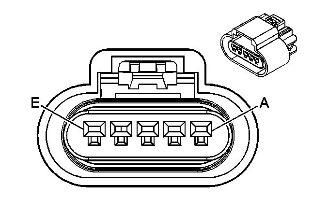
Connector Part Information
|
Terminal Part Information
|
Pin | Wire Color | Circuit No. | Function |
|---|---|---|---|
A | 0.5 YE | 492 | MAF Sensor Signal |
B | 0.5 PK | 1839 | Ignition 1 Voltage |
C | 0.5 BK/WH | 451 | Ground |
D | 0.5 TN/BK | 472 | IAT Sensor Signal |
E | 0.5 TN | 2760 | Low Reference |
Throttle Body
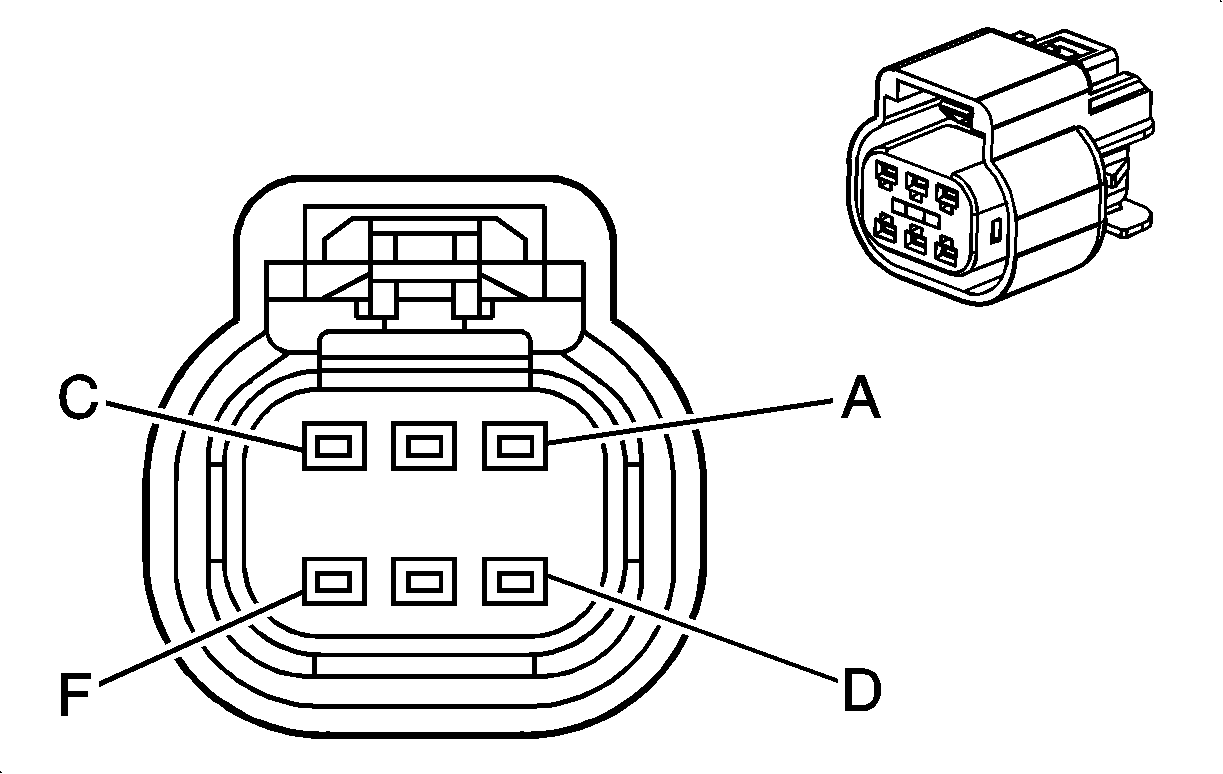
Connector Part Information
|
Terminal Part Information
|
Pin | Wire Color | Circuit No. | Function |
|---|---|---|---|
A | 0.5 BN | 582 | TAC Motor Control - 2 |
B | 0.5 YE | 581 | TAC Motor Control - 1 |
C | 0.35 TN | 2752 | Low Reference |
D | 0.35 D-GN | 485 | TP Sensor 1 Signal |
E | 0.35 GY | 2701 | 5-Volt Reference |
F | 0.35 PU | 486 | TP Sensor 2 Signal |
Valve Lifter Oil Manifold (VLOM) Assembly (-4.8L)
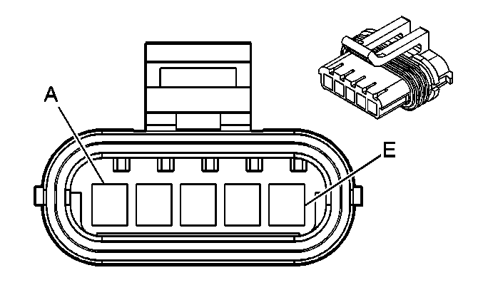
Connector Part Information
|
Terminal Part Information
|
Pin | Wire Color | Circuit No. | Function |
|---|---|---|---|
A | 0.5 OG | 5494 | Cylinder 4 Shutoff Solenoid Control 2 |
B | 0.5 GY | 5493 | Cylinder 6 Shutoff Solenoid Control 3 |
C | 0.5 D-BU | 5491 | Cylinder 1 Shutoff Solenoid Control 1 |
D | 0.5 L-GN | 5492 | Cylinder 7 Shutoff Solenoid Control 4 |
E | 0.5 PK | 1839 | Ignition 1 Voltage |
