Danger: Ensure all High Voltage safety procedures are followed. Failure to follow the procedure exactly as written may result in serious injury or death.
Danger: Before working on any high voltage system, be sure to wear the following Personal Protection Equipment:
| • | Safety glasses with appropriate side shields when within 50 feet of the vehicle, either indoors or outdoors |
| • | Certified and up-to-date Class "0" Insulation gloves rated at 1000V with leather protectors |
| - | Visually and functionally inspect the gloves before use. |
| - | Wear the Insulation gloves at all times when working with the high voltage battery assembly, whether the system is energized or not. |
Important: Use the correct procedure, depending on components being serviced, to disable the High Voltage system.
Refer to one of the following procedures below depending on components being serviced:
| • | When Servicing Drive Motor Generator Battery Assembly or 300 V DC Cable |
| • | When Servicing Drive Motor Generator Control Module Assembly or Cable Connections |
When Servicing Drive Motor Generator Battery Assembly or 300 V DC Cables
- Review the high voltage safety information prior to performing the High Voltage Disabling procedure. Refer to
High Voltage Safety.
- Disable the voltage sources to the 2 mode hybrid vehicle.
| 2.1. | Remove the ignition key. |
| 2.2. | Remove the rear seat frame front finish cover. |
| 2.3. | Remove the high voltage manual disconnect lever. Attach the ignition key to the lever and put the lever and the ignition key in a secure place. |
| ⇒ | Wait 5 minutes before continuing, to allow the capacitors to discharge. |
Important: The 12 V battery must be disconnected to ensure proper test results.
- Disconnect the 12 V battery. Refer to
Battery Negative Cable Disconnection and Connection.
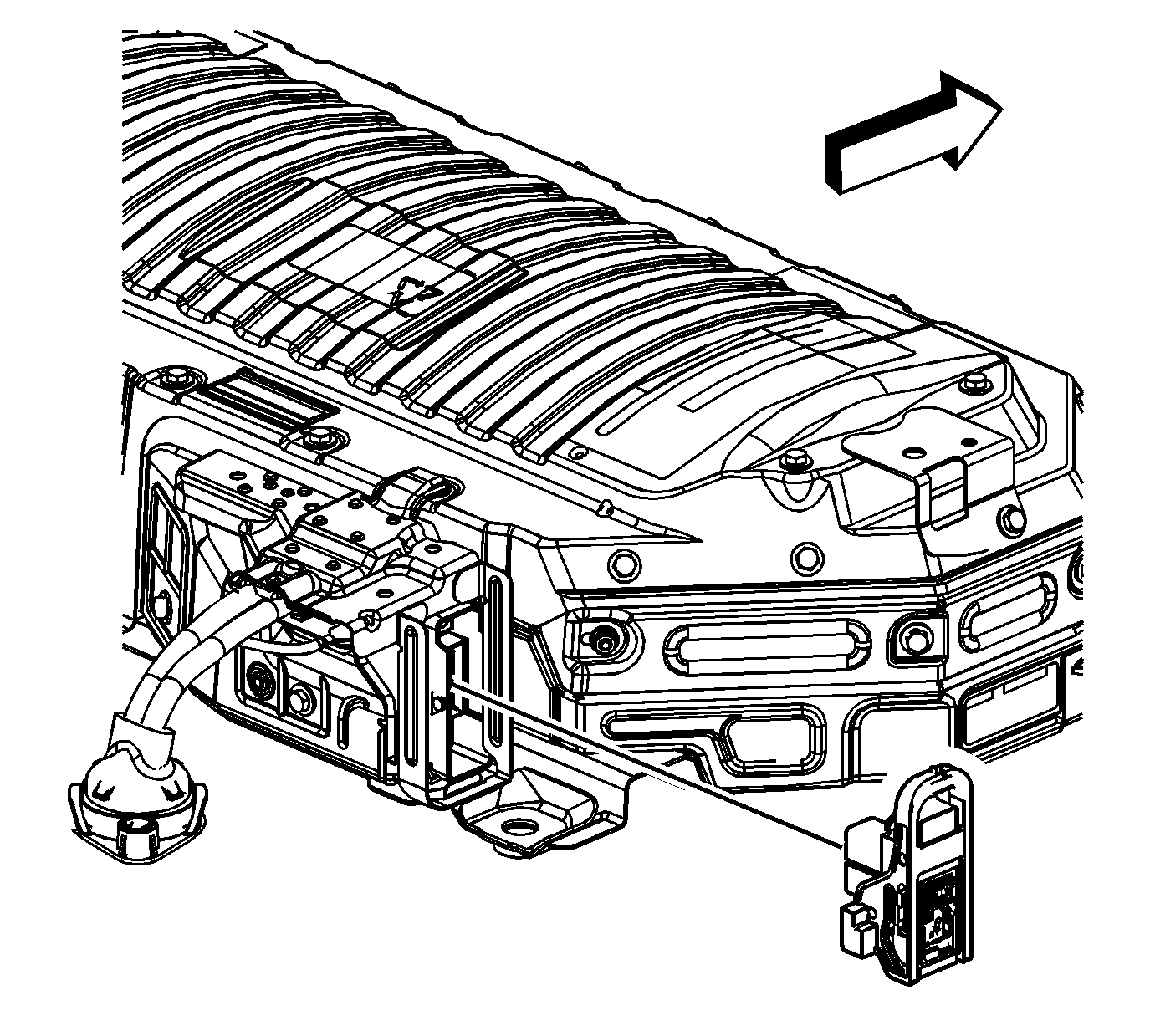
- Remove the rear seat riser finish cover.
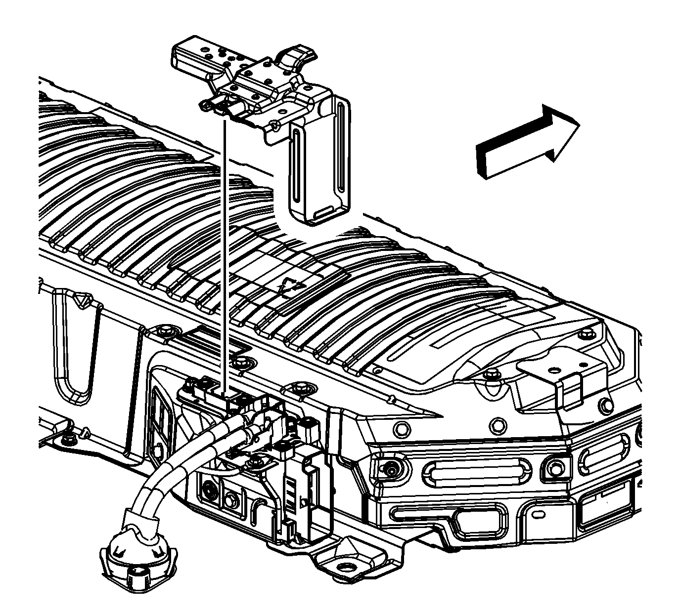
Important: Wear your High Voltage Insulation gloves until you have determined that a high voltage exposure risk is no longer present.
- Remove the terminal extension cover assembly.
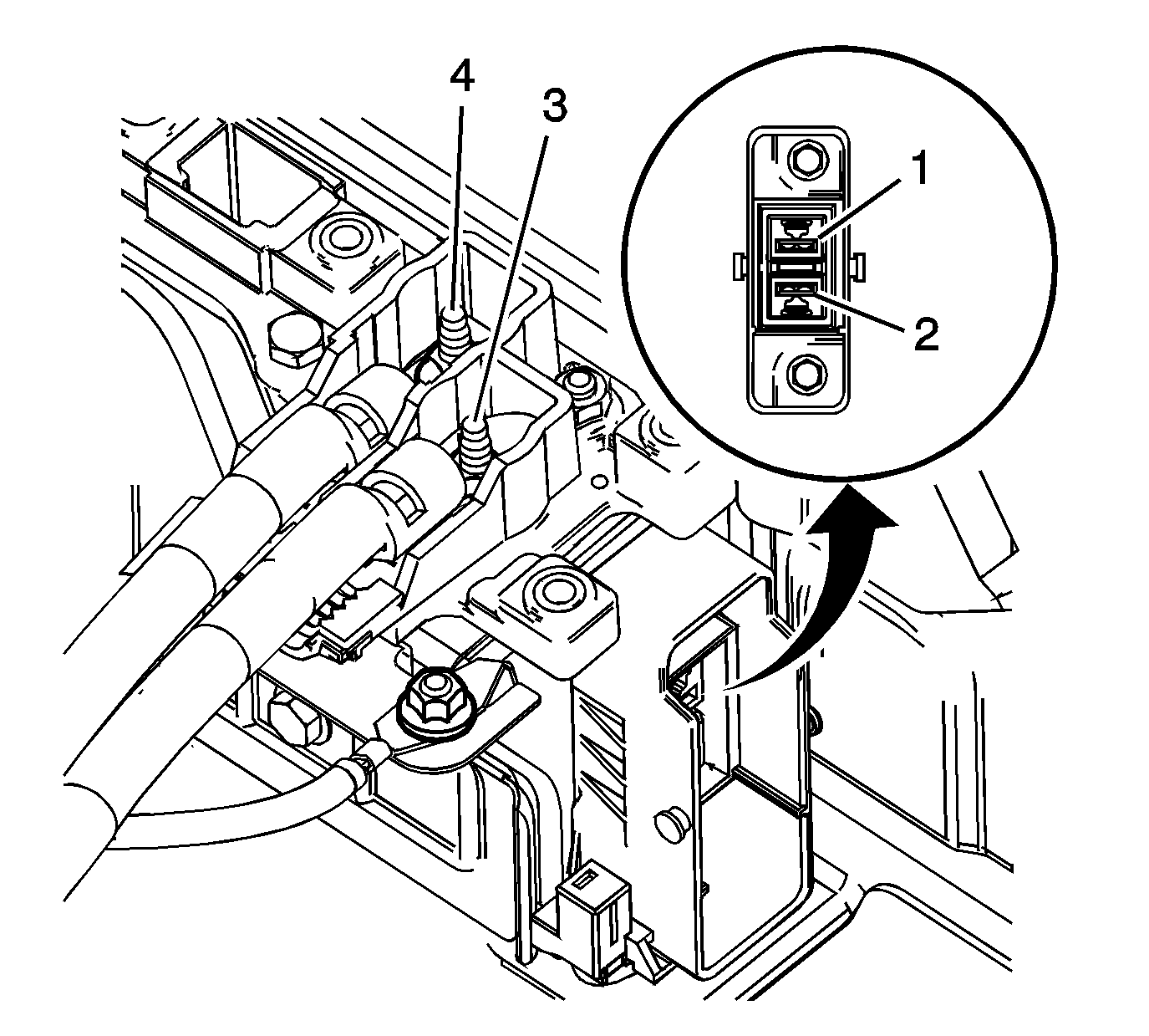
- To verify that the voltage has been disabled at the drive motor generator battery assembly terminals, perform the following:
| 6.1. | Set the digital multimeter (DMM) to DC mode. Verify the DMM works by measuring the voltage of the 12 V battery. |
| 6.2. | Using the DMM, verify the voltage measures less than 3 V at the following points: |
| 6.2.1. | Across the HVDC (+) positive (3) and HVDC (-) negative (4) terminals |
| ⇒ | If the test result was greater than 3 V, the drive motor generator control module internal capacitors are still charged. Keep the insulation gloves on and install the cable cover. Wait 5 minutes and then remove the cover and return
to the beginning of this step. |
| 6.2.2. | HVDC (+) positive (3) to vehicle chassis ground |
| 6.2.3. | HVDC (-) negative (4) to vehicle chassis ground |
- Using a DMM test for voltage from the High Voltage manual disconnect terminal (1) to the High Voltage DC positive and negative terminal connections (3, 4). The result should be less than 3 V.
- Using a DMM test for voltage from the High Voltage manual disconnect terminal (2) to the high voltage DC positive and negative terminal connections (3, 4). The result should be less than 3 V.
- Retest the DMM by measuring the 12 V battery.
| ⇒ | If the DMM does not properly measure the 12 V battery, repair or replace the DMM and repeat all voltage measurements. |
| ⇒ | If all the test results were less than 3 V, the 300 V DC cables can now be removed from the drive motor generator battery assembly. |
When Servicing Drive Motor Generator Control Module Assembly or Cable Connections
- Disable the voltage sources to the 2 mode hybrid vehicle.
| 1.1. | Remove the ignition key. |
| 1.2. | Remove the rear seat frame front finish cover. |
| 1.3. | Remove the high voltage manual disconnect lever. Attach the ignition key to the lever and put the lever and the ignition key in a secure place. |
| ⇒ | Wait 5 minutes before continuing, to allow the capacitors to discharge. |
Important: The 12 V battery must be disconnected to ensure proper test results.
- Disconnect the 12 V battery. Refer to
Battery Negative Cable Disconnection and Connection.
- Remove the drive motor generator control module sight shield. Refer to
Drive Motor Generator Control Module Sight Shield Replacement.
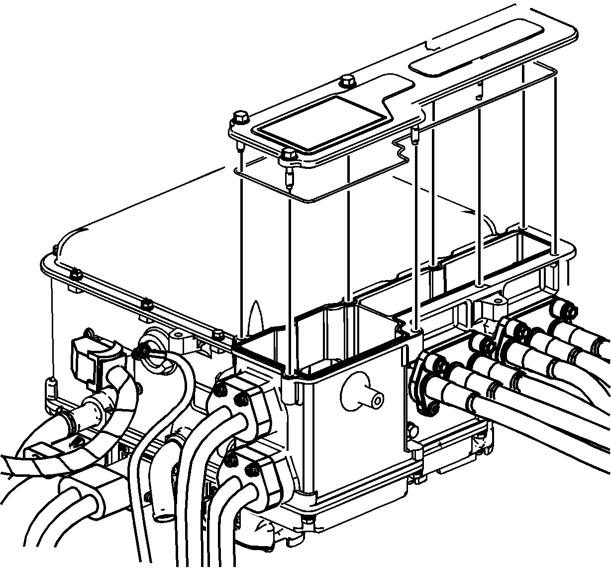
Important: Wear your High Voltage Insulation gloves until you have determined that a high voltage exposure risk is no longer present.
- Remove the 3 phase cable cover.
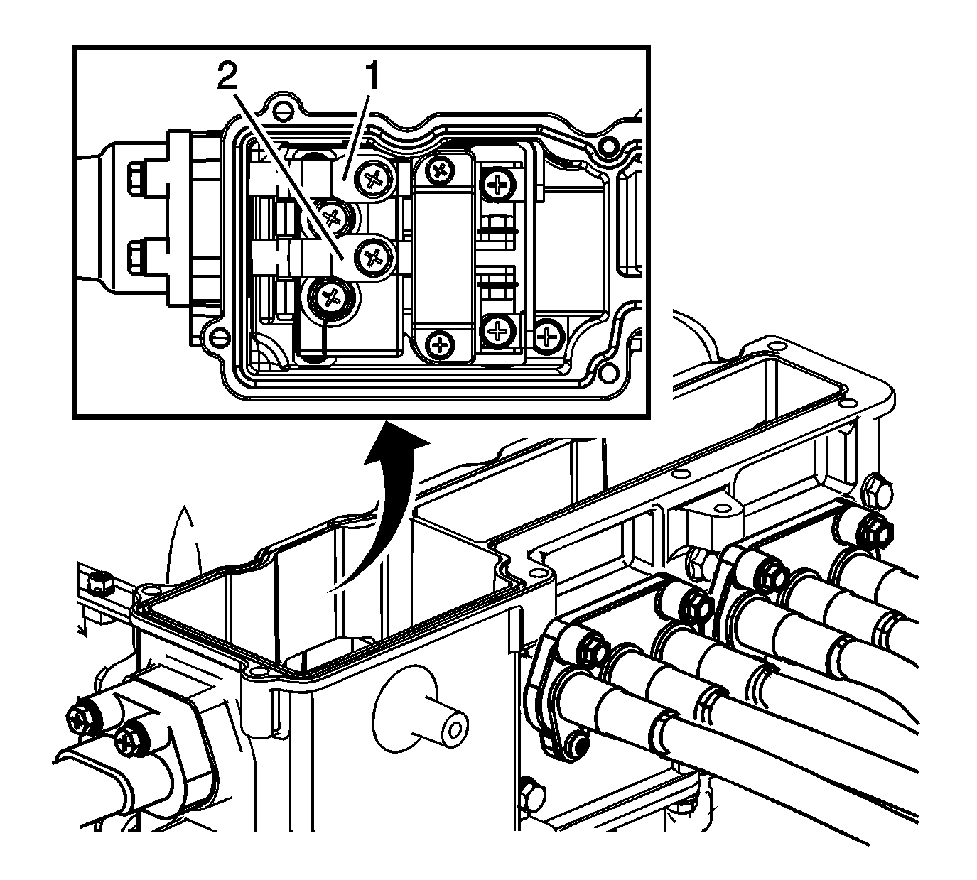
- To verify that no voltage is present at the high voltage connection for the drive motor generator control module, perform the following:
| 5.1. | Set the digital multimeter (DMM) to DC mode. Verify the DMM works by measuring the voltage of the 12 V battery. |
| 5.2. | Using the DMM, verify the voltage measures less than 3 V at the following points: |
| 5.2.1. | Across the HVDC (+) positive (1) and HVDC (-) negative (2) terminals |
| ⇒ | If the test result was greater than 3 V, the drive motor generator control module internal capacitors are still charged. Keep the insulation gloves on and install the 3 phase cable cover. Wait 5 minutes and then remove the 3 phase
cable cover and return to the beginning of this step. |
| 5.2.2. | HVDC (+) positive (1) to vehicle chassis ground |
| 5.2.3. | HVDC (-) negative (2) to vehicle chassis ground |
- Retest the DMM by measuring the 12 V battery.
| ⇒ | If the DMM does not properly measure the 12 V battery, repair or replace the DMM and repeat all voltage measurements. |
| ⇒ | If all the test results were less than 3 V, the cables can now be removed from the drive motor generator control module assembly. |


