Tools Required
| • | J 24385-C Axle Housing Spreader |
| • | J 25025 Guide Pins |
| • | J 34178 Spreader Gage Adapter |
| • | J 8001 Dial Indicator Set |
Removal Procedure
- Raise the vehicle. Refer to Lifting and Jacking the Vehicle .
- Remove the axle shafts. Refer to Front Axle Shaft Replacement .
- Remove the front cover. Refer to Differential Carrier Assembly Cover and/or Gasket Replacement .
- Support the front axle assembly.
- Remove the U-bolts from the front axle assembly, and lower the axle.
- Loosen the bearing cap bolts.
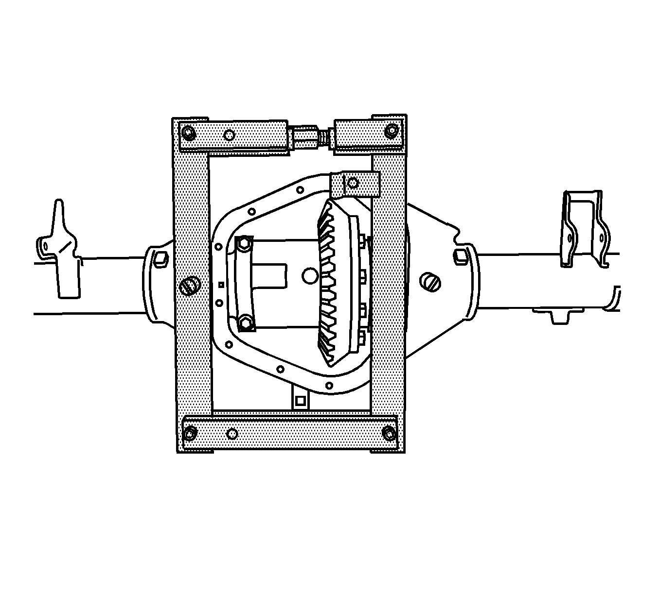
- Install the J 24385-C onto the axle housing as shown.
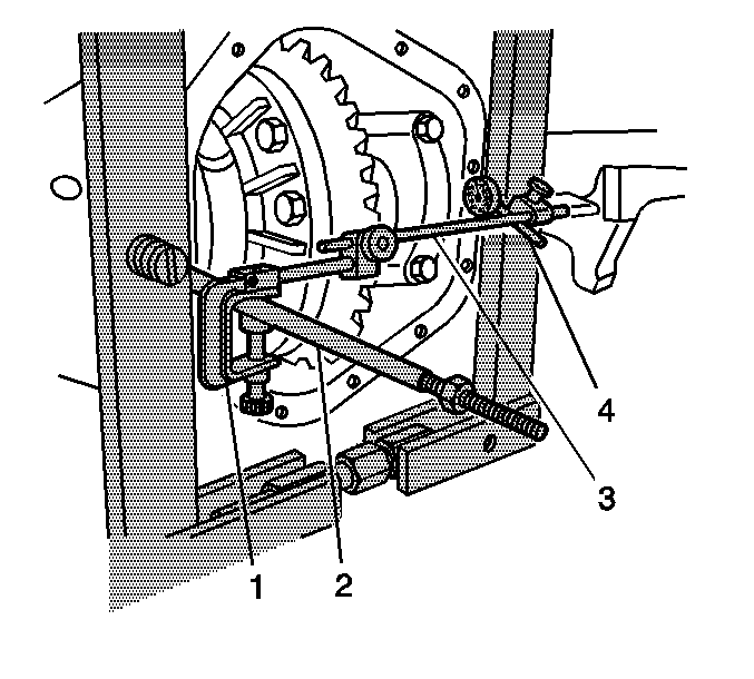
- Install the J 25025 (2), the J 8001-1 and the J 8001-2 (1), the J 34178 (3), and the J 8001-3 and the J 8001-4 (4) onto the axle housing as shown.
- Preload the dial of the J 8001-3 by pushing the J 8001-3 against the edge of the J 24385-C until the needle of the J 8001-3 has moved approximately 3/4 of a turn clockwise.
- Rotate the indicator housing to align the indicator needle of the J 8001-3 and the dial indicator face to ZERO.
- Spread the axle housing by turning the clevis screw of the J 24385-C clockwise while observing the J 8001 .
- Remove the J 25025-B , the J 8001-1 , the J 8001-2 , the J 34178 , the J 8001-3 and the J 8001-4 from the axle housing.
- Remove the bearing cap bolts.
- Remove the bearing caps.
- Remove the differential assembly.
- Remove the J 24385-C .
- Remove the ring gear. Refer to Drive Pinion and Ring Gear Replacement .
- Remove the differential side bearings, if necessary. Refer to Differential Side Bearing Replacement .
Do not remove the bearing cap bolts at this time.


Notice: Do not spread the axle housing more than 0.38 mm (0.015 inch). Overspreading the housing may result in component damage.
Spread the housing just enough to remove the differential assembly.
Caution: Refer to Differential Case Removal Caution in the Preface section.
Important: Corresponding letters are stamped on the bearing caps and axle housing. The bearing caps must be reassembled in the same position as removed.
Installation Procedure
- Install the ring gear. Refer to Drive Pinion and Ring Gear Replacement .
- Install the differential side bearings, if necessary. Refer to Differential Side Bearing Replacement .
- Install the J 24385-C onto the axle housing.
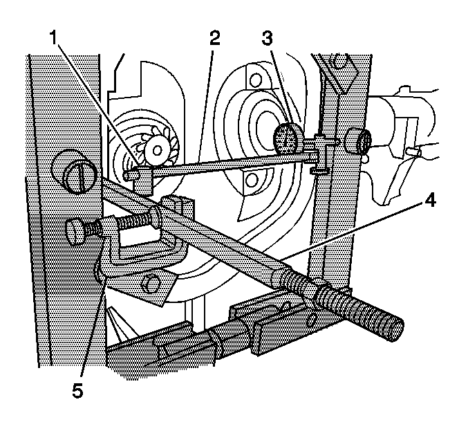
- Install the J 25025-B (4), the J 8001-1 and the J 8001-2 (5, 1), the J 34178 (2), and the J 8001-3 and the J 8001-4 (3) onto the axle housing as shown.
- Preload the dial of the J 8001-3 by pushing the J 8001-3 against the edge of the J 24385-C until the needle of the J 8001-3 has moved approximately 3/4 of a turn clockwise.
- Rotate the indicator housing to align the indicator needle of the J 8001-3 and the dial indicator face to ZERO.
- Spread the axle housing by turning the clevis screw of the J 24385-C clockwise while observing the J 8001 .
- Remove the J 25025-B , the J 8001-1 , the J 8001-2 , the J 34178 , the J 8001-3 and the J 8001-4 from the axle housing.
- Install the differential assembly.
- Remove the J 24385-C .
- Install the bearing caps.
- Install the bearing cap bolts.
- Install new U-bolts to the front axle assembly.
- Install the front cover. Refer to Differential Carrier Assembly Cover and/or Gasket Replacement .
- Install the axle shafts. Refer to Front Axle Shaft Replacement .
- Fill the axle with the proper lubricant. Refer to Front Axle Lubricant Replacement .
- Lower the vehicle.

Notice: Do not spread the axle housing more than 0.38 mm (0.015 inch). Overspreading the housing may result in component damage.
Spread the housing just enough to install the differential assembly.
Important: Corresponding letters are stamped on the bearing caps and axle housing. The bearing caps must be reassembled in the same position as removed.
Notice: Refer to Fastener Notice in the Preface section.
Tighten
Tighten the bearing cap bolts to 109 N·m (80 lb ft).
Important: Always replace the U-bolts when loosened or removed.
Tighten
Tighten to 330 N·m (243 lb ft).
