- Clean all the parts in
a suitable cleaning solvent. Air dry all the parts.
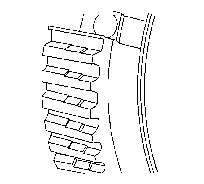
- Inspect the synchronizer sleeves for a sliding fit on the synchronizer
hubs.
- Replace the 3rd and 4th gear synchronizer hub that does not require
a force fit on the mainshaft splines.
- Inspect the synchronizer hub for wear on the external splines.
A stepped effect on the teeth, due to wear, may cause shift conditions.
- Inspect the 3rd and 4th gear synchronizer hub for a force fit
on the mainshaft splines.
- Replace a worn hub.
- Correct the cause such as, but not limited to, the following:
| • | Engine related vibrations |
| • | Driving at a low speed in a high gear |
| • | Defective vibration damper or crankshaft |
| • | Incorrectly set injector pump |
- Inspect the inserts and springs for wear or damage.
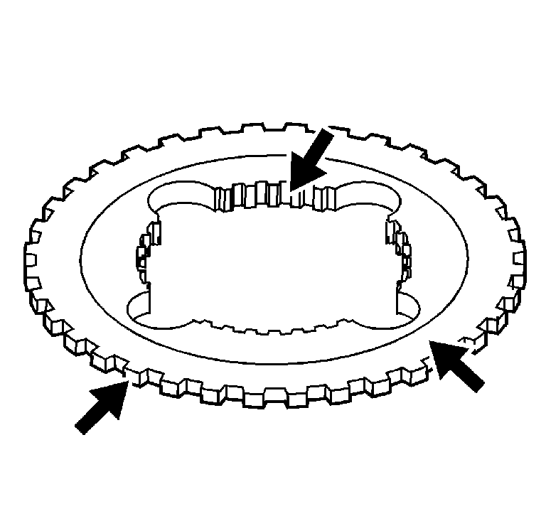
- Inspect the mainshaft
drive gear clutch gear teeth for wear.
- Inspect the input shaft clutch gear teeth for wear.
- Inspect the clutch gear for 4th gear, reverse gear, and overdrive
gear wear.
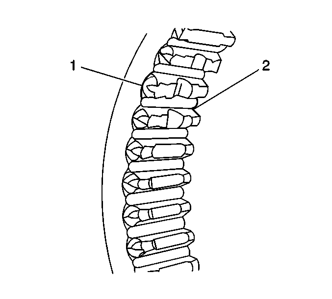
- Inspect the synchronizer
sleeve teeth (1) for the following, which may cause shift conditions:
- Inspect the synchronizer sleeve detent stops (2) for wear
or for being chipped off.
- Replace the synchronizer assembly if the teeth or stops show the
above conditions.
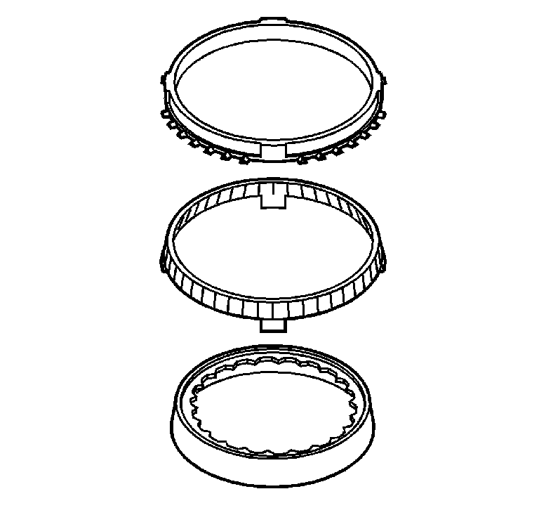
- Inspect the three-piece
1st/2nd synchronizer blocker rings for wear.
- Replace the blocker ring assembly if the middle ring grooves
are worn away.
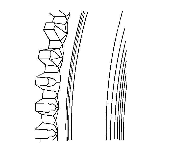
- Inspect all of the synchronizer
blocker rings for worn shift teeth.
- Inspect the blocker rings for worn friction material.
- Replace the synchronizer ring assembly if any of the above conditions
are present.
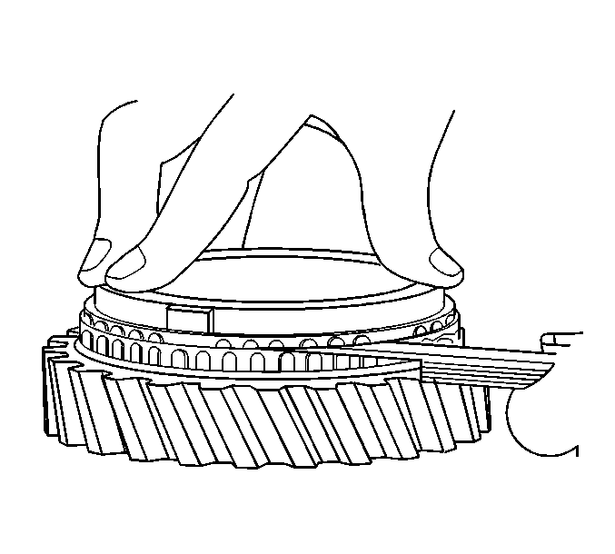
Important: The wear of the 1st/2nd speed synchronizers can only be measured correctly
while the speed gears are installed on the mainshaft. The synchronizer uses
a fixed inner cone. Refer to
Main Shaft Disassemble
.
- Measure the gap between the verical faces of the blocking ring teeth
and the synchronizer clutch gear as follows:
| 20.1. | Assemble the correct blocker ring to the correct gear. |
| 20.2. | Apply pressure to the blocker ring to fully seat the ring. |
| 20.3. | Using a feeler gauge, measure between the blocker ring teeth and
the teeth on the gear. |
| • | 3rd gear 1.73-0.76 mm (0.068-0.030 in) |
| • | 4th gear 2.10-1.19 mm (0.079-0.047 in) |
| • | Overdrive gear 1.83-1.07 mm (0.072-0.042 in) |
| • | Reverse gear 2.24-1.47 mm (0.088-0.058 in) |
- If a NEW blocker ring is used, and the standard clearance cannot
be obtained, replace the gear.


