Tools Required
| • | J 23907 Slide
Hammer with Bearing Adapter |
| • | J 26941 Bushing
and Bearing Remover - 3-4 inch |
| • | J 36513 Gear
and Bearing Separator Plate |
| • | J 44737 Shift
Rail Bearing Remover |
| • | J 45380 Transfer
Case Rear Bushing Remover and Installer |
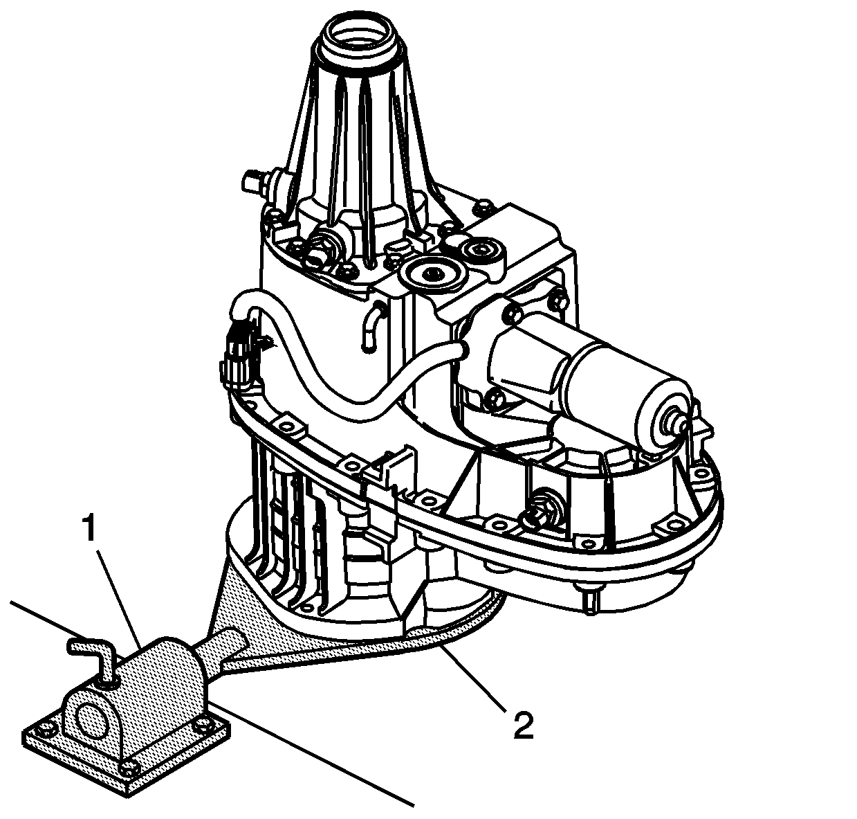
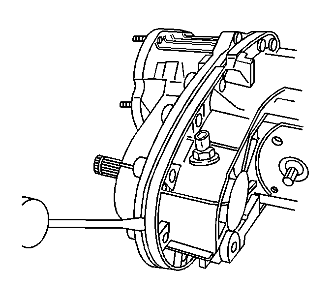
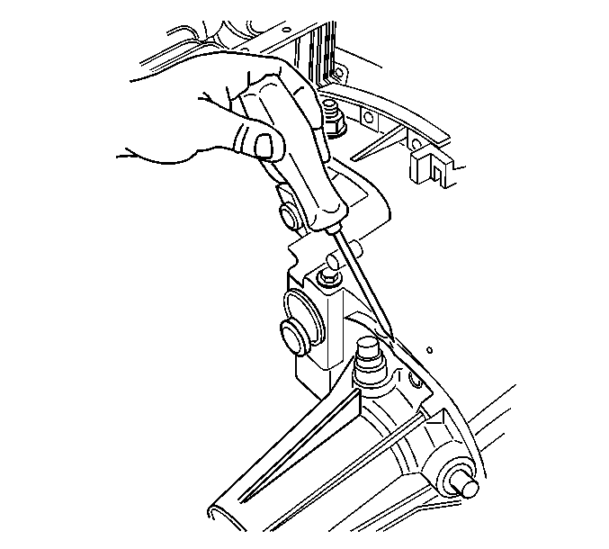
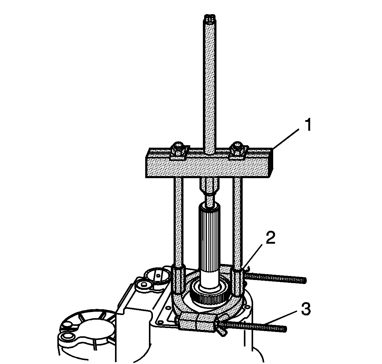
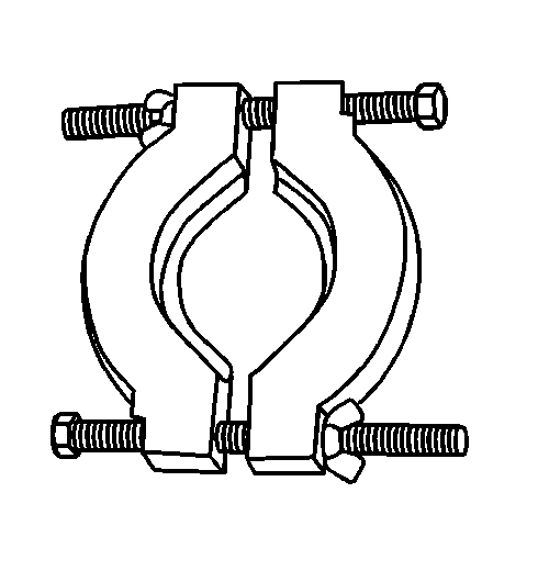
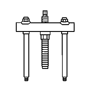
- If available, using the
adapter studs, attach the J 45759
(2) to the transfer case.
- Mount the J 3289-20
(1) to a sturdy workbench.
- Install the J 45759
(2) into the J 3289-20
(1) and secure with pivot pins.
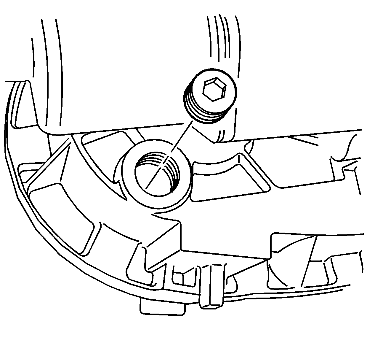
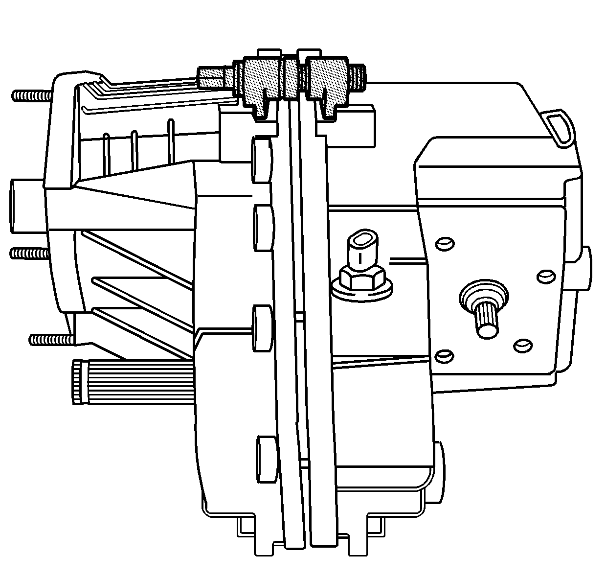
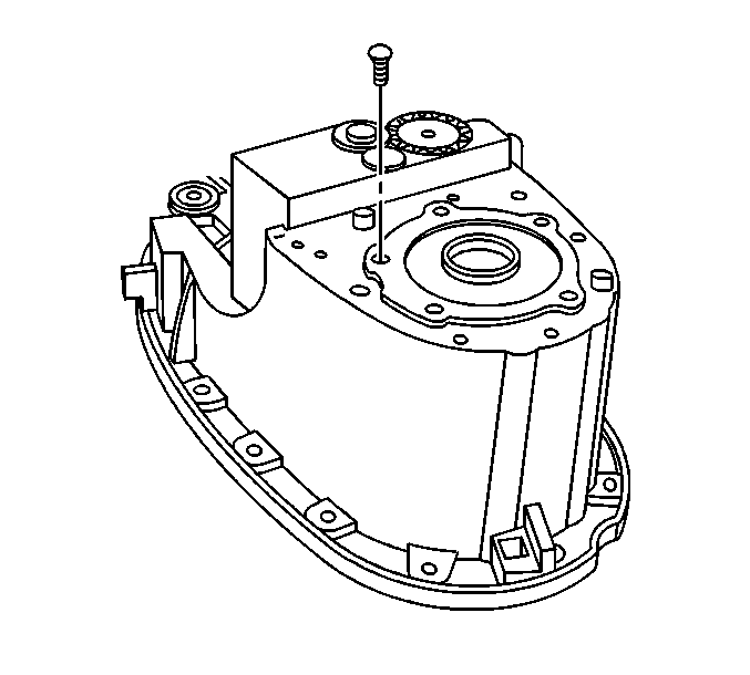
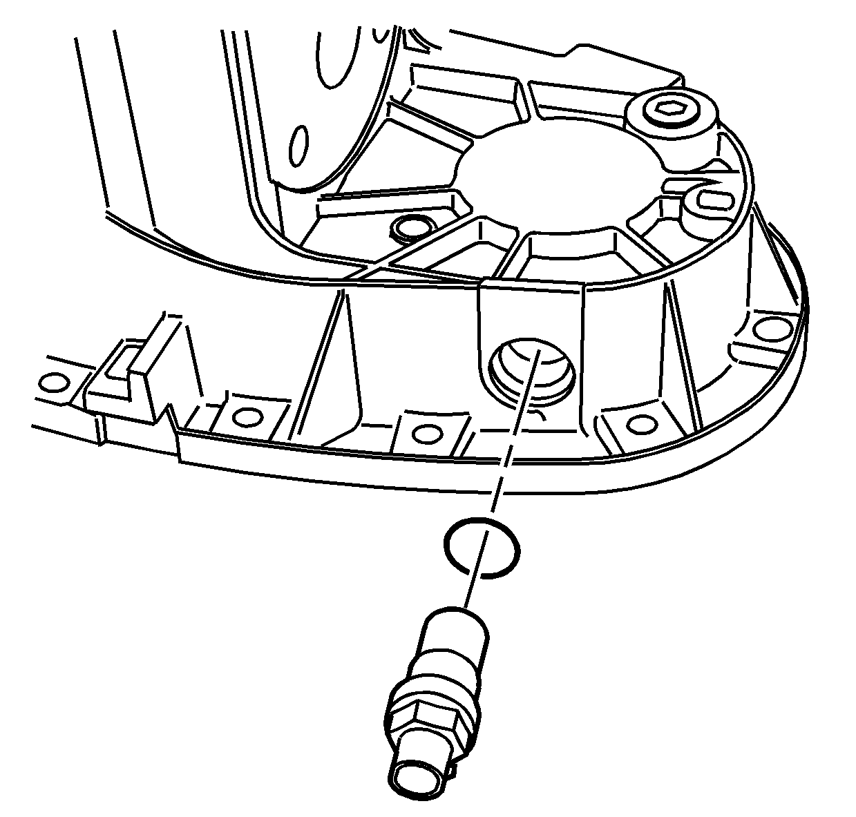
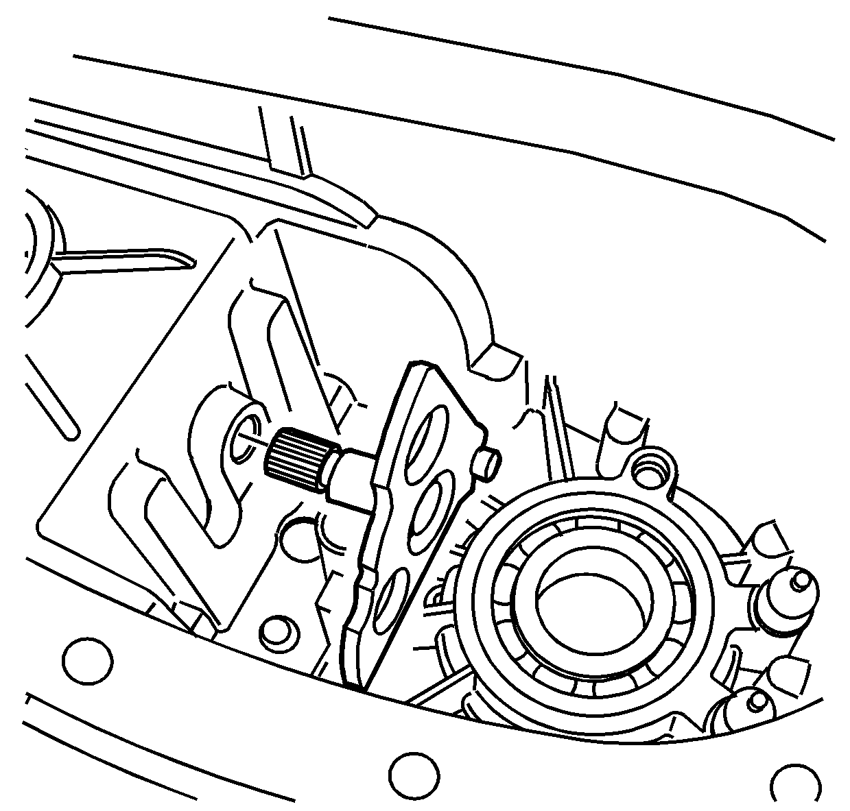
- Remove the drain plug.
- Tip the transfer case to remove any remaining transfer case fluid.
Notice: Refer to Transfer Case Seal Removal Notice in the Preface section.
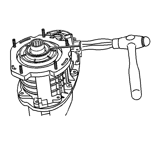
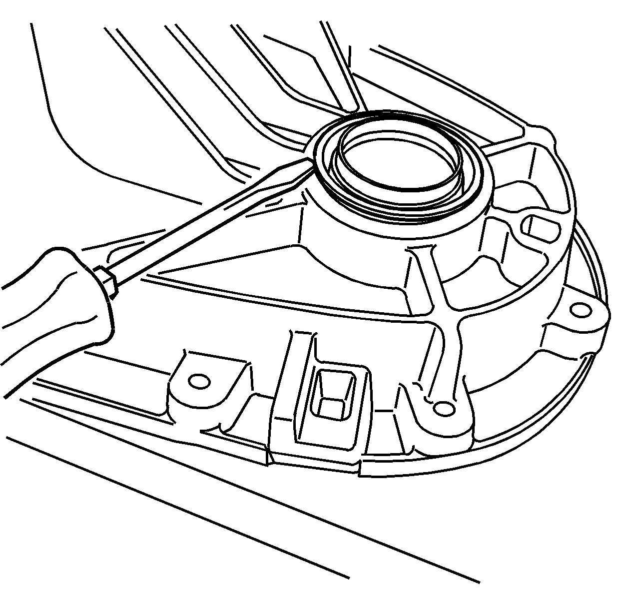
- Using a fine flat-bladed screwdriver and a mallet, loosen the
front input shaft seal.
- Using a small block of
wood and a large flat-bladed screwdriver, remove the front input
shaft seal from the transfer case.
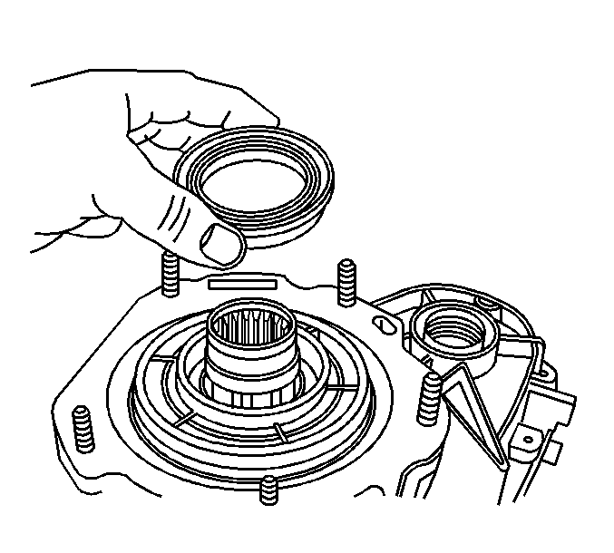
- Remove the front input
shaft seal.
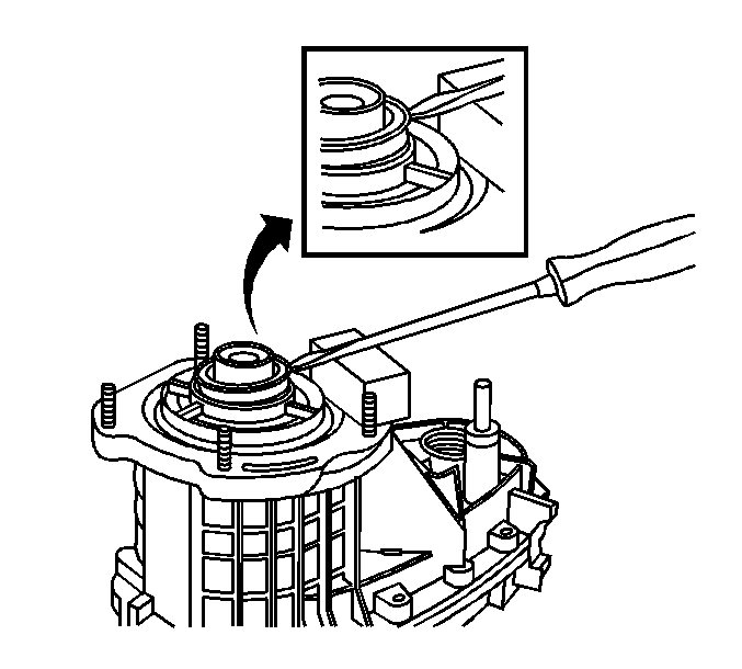
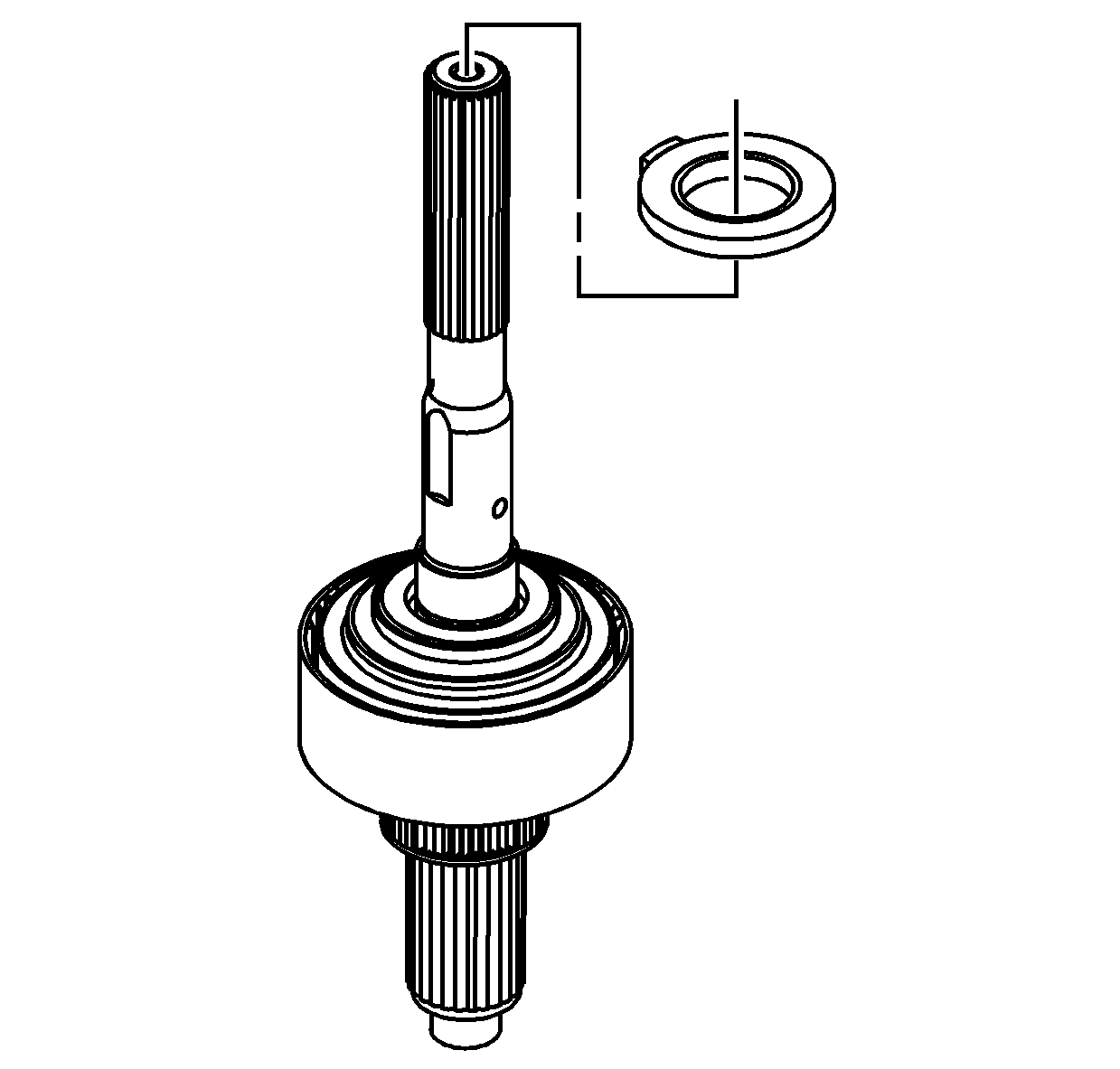
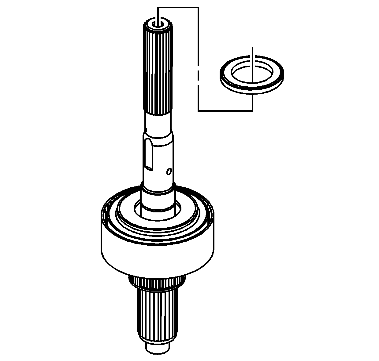
- Remove the dust seal from
the front output shaft. The front output shaft oil seal does not require
removal at this time.
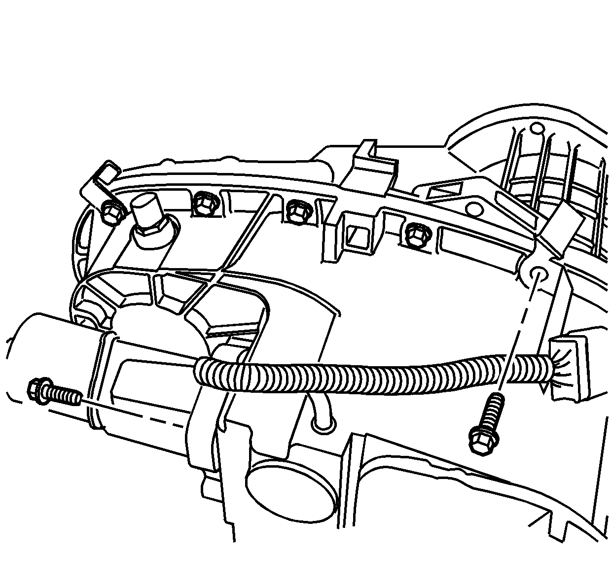
- Remove the transfer case
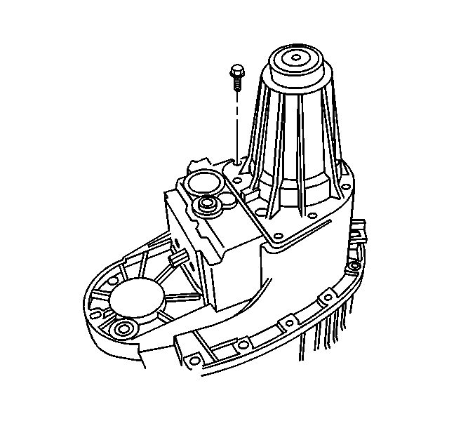
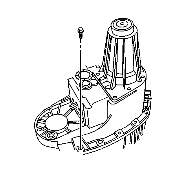
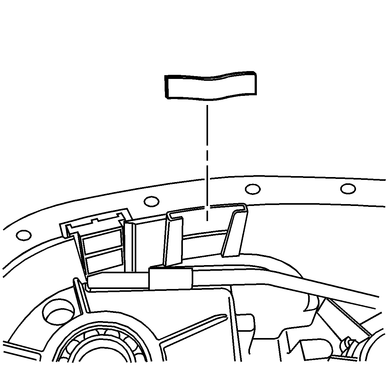
bolt retaining the wiring harness bracket.
- Mark the location of the wiring harness bracket bolt.
- Remove the encoder/motor mounting bolts.
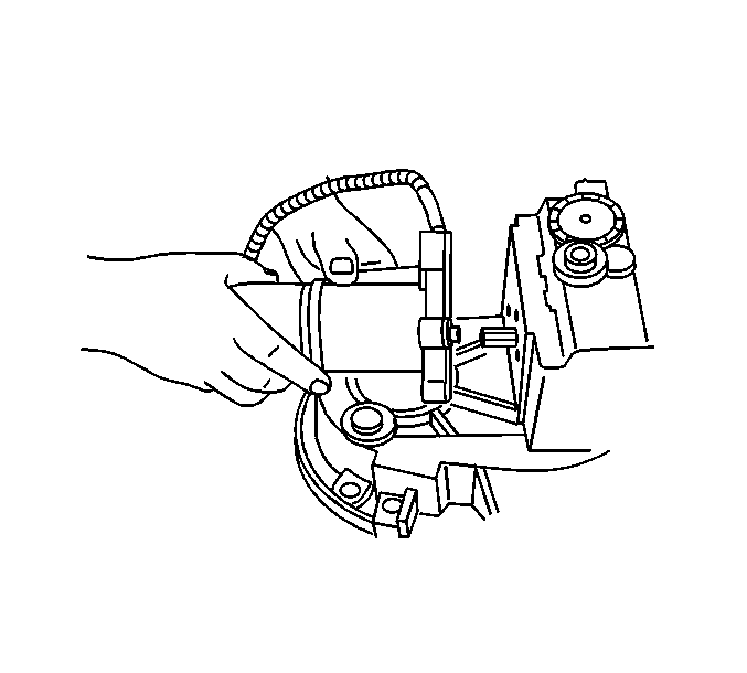
- Remove the encoder/motor
assembly.
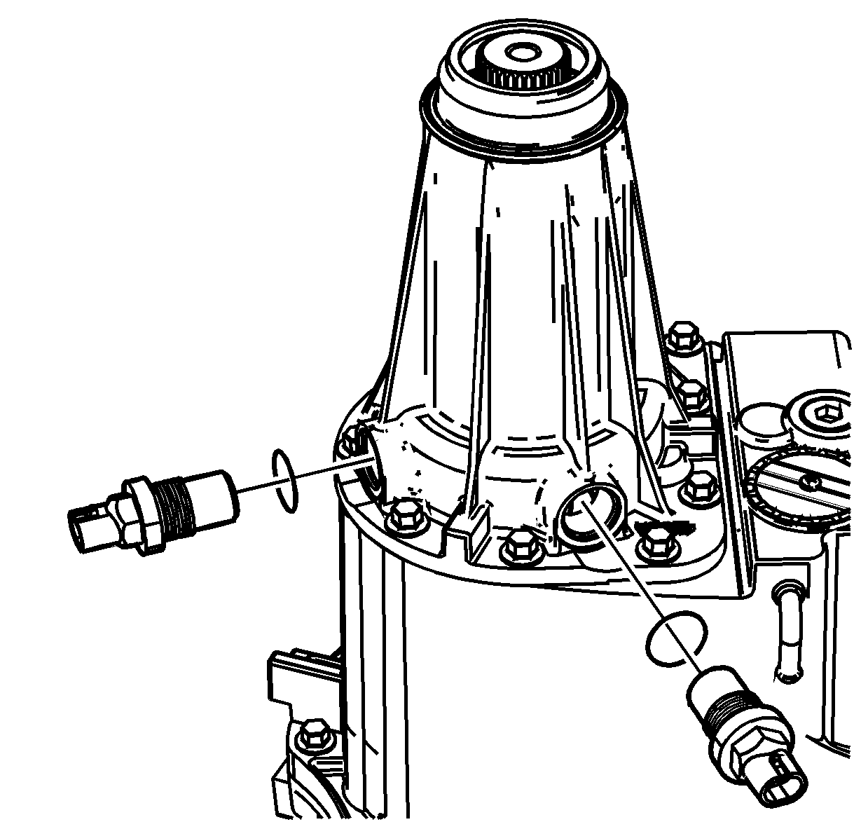
- Remove both vehicle speed
sensors (VSS) and O-ring seals from the rear extension.
Notice: Refer to Transfer Case Seal Removal Notice in the Preface section.
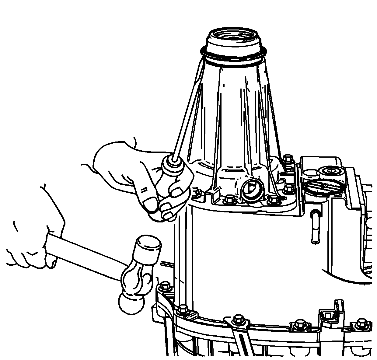
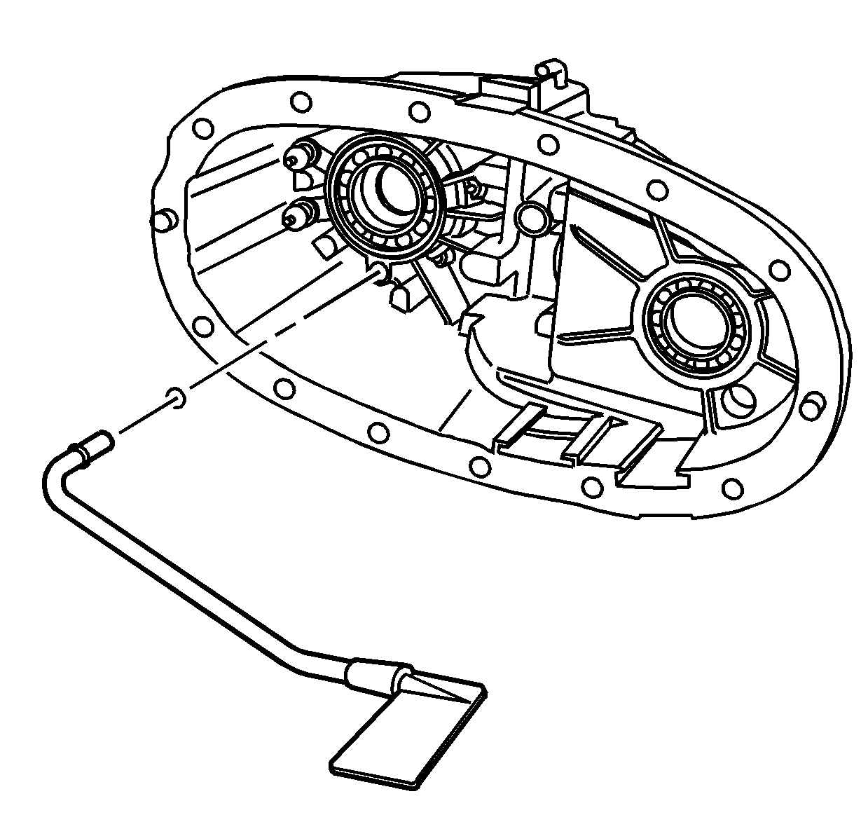
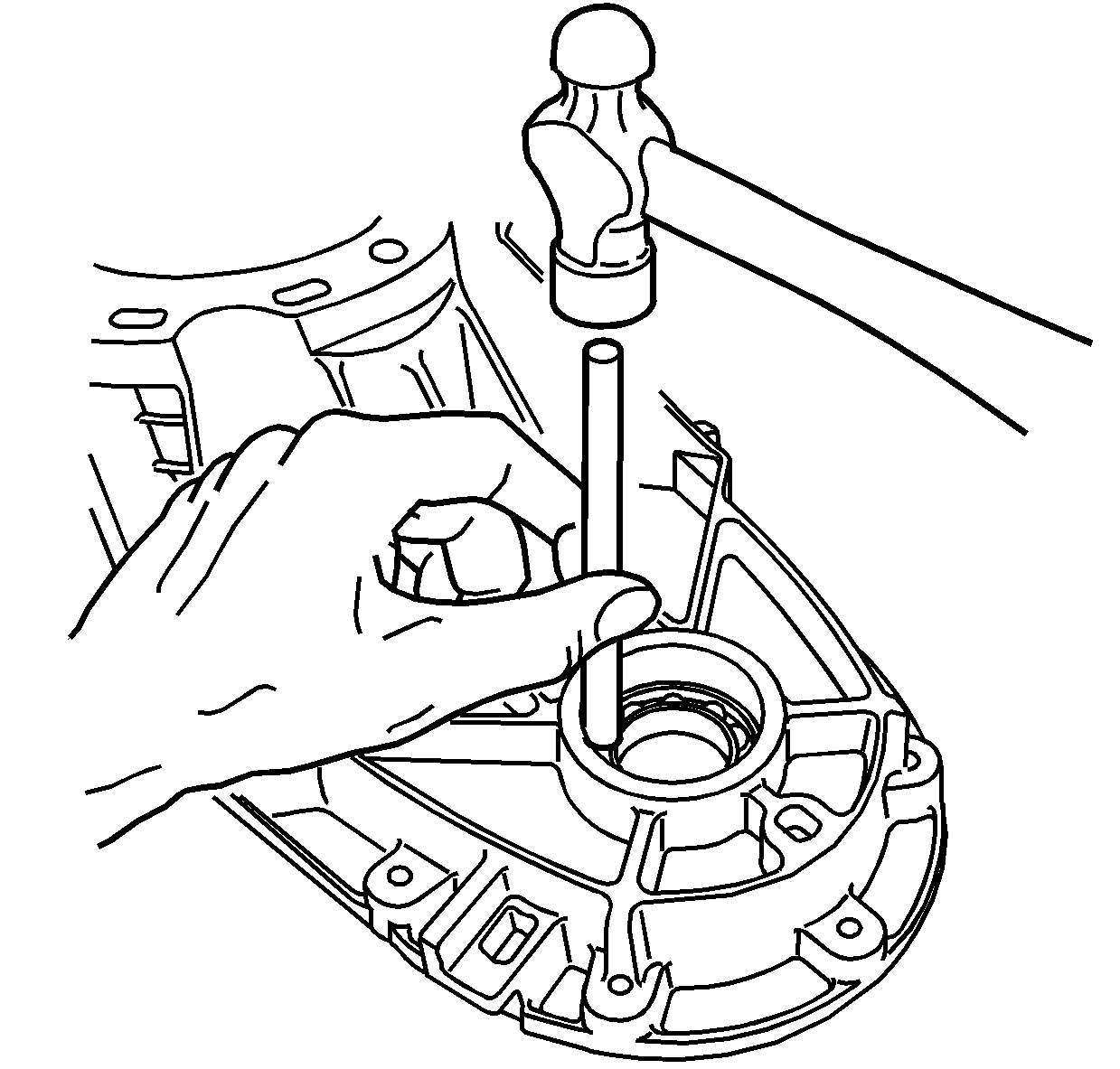
- Using a hammer and a punch, remove the rear output seal.
The rear extension bushing is not serviceable.

- Inspect the rear output shaft bushing
for scoring or wear.
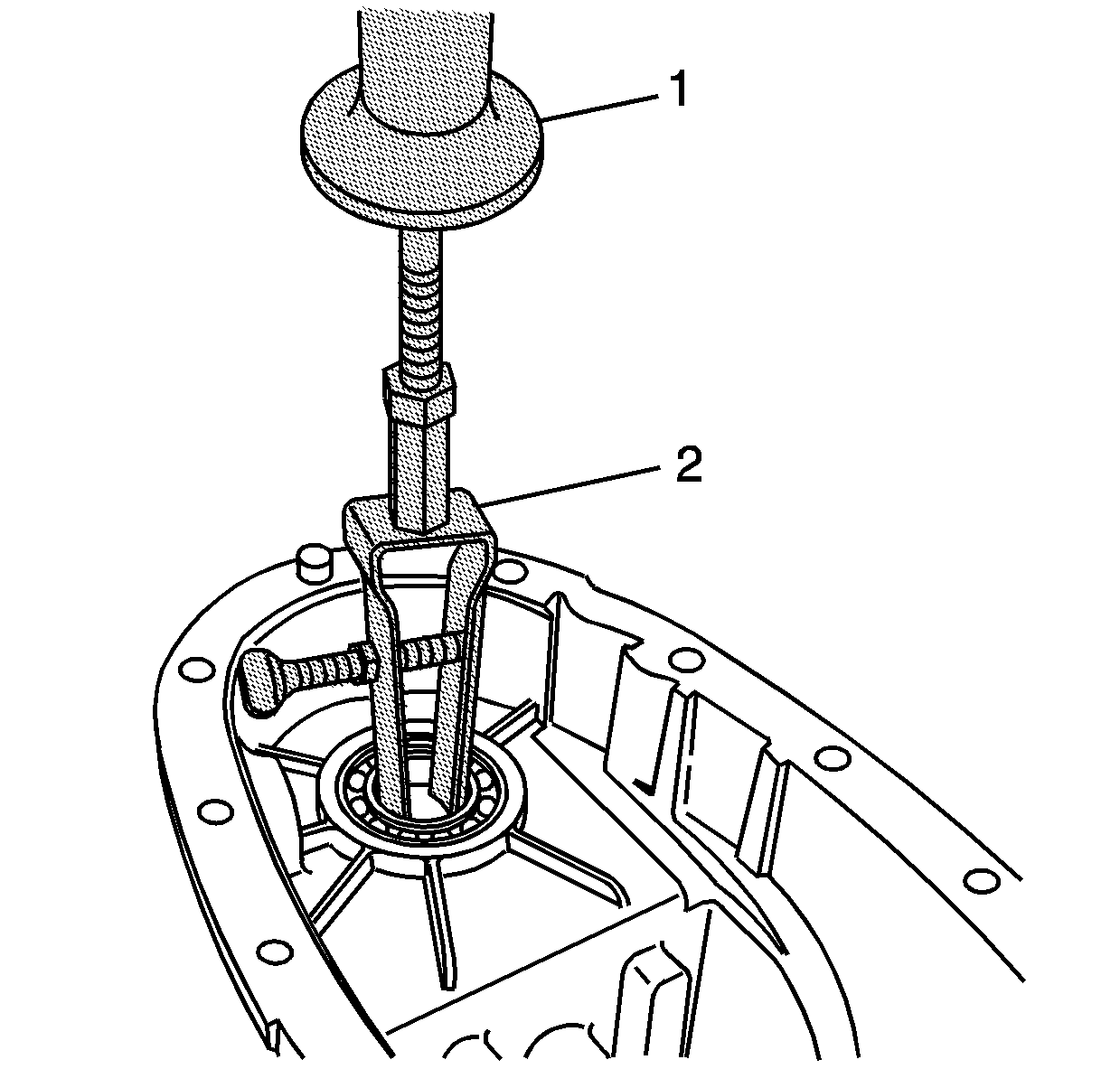
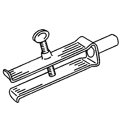
- Remove the rear output shaft bushing using the J 45380
.
| • | Install the finger section of the J 45380
in front of the bushing. |
| • | Install the tube and forcing screw assembly to the finger section.
Ensure the forcing screw is backed out. |
| • | Using a wrench on the forcing screw, remove the rear output shaft
bushing. |
Important: Remove the rear extension and case half bolts at the same time for easier
rear case disassembly.
- Remove the rear extension mounting bolts.
- Remove the case half bolts.
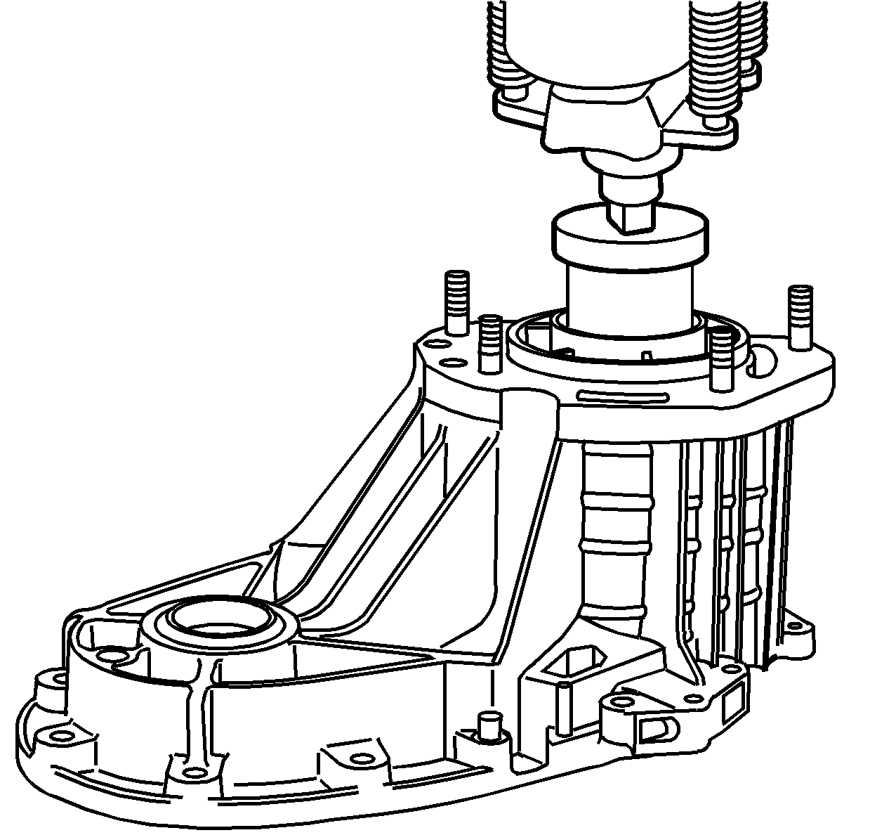
Notice: Refer to Machined Surface Damage Notice in the Preface section.
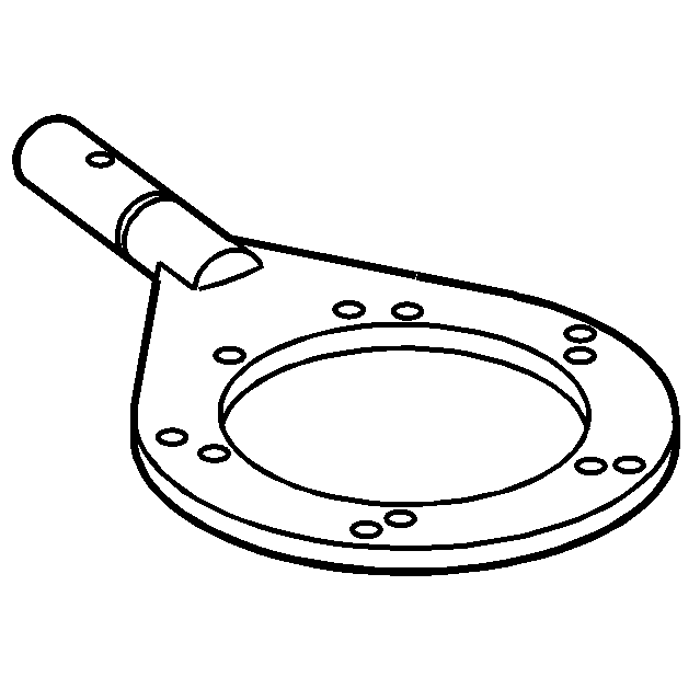
- Install the J 45358
between the tabs on one side of the case.
Important:
| • | Ensure that all of the case half bolts have been removed. |
| • | DO NOT use screwdrivers or pry bars to separate the transfer case halves.
The special tool must be used to separate the transfer case halves properly. |
- Using the J 45358
,
shear the sealer securing the front and rear case half together.
- Move the J 45358
to the tabs on the other side of the case and shear the sealer.
- Use a suitable prying
tool at one side of the case half.
- Use a suitable prying
tool at the other side of the cased halves.
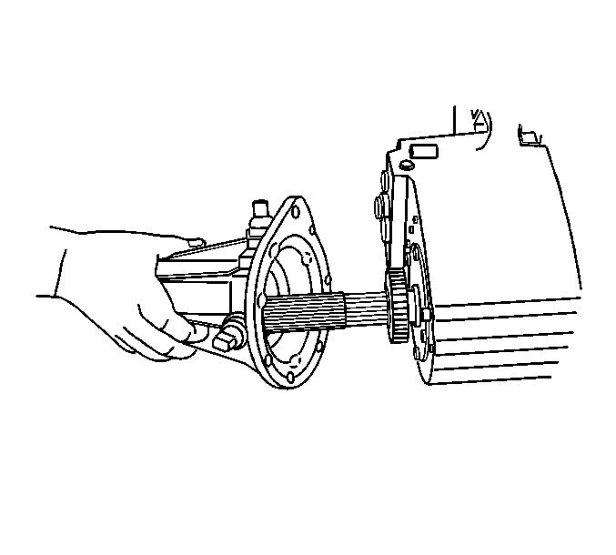
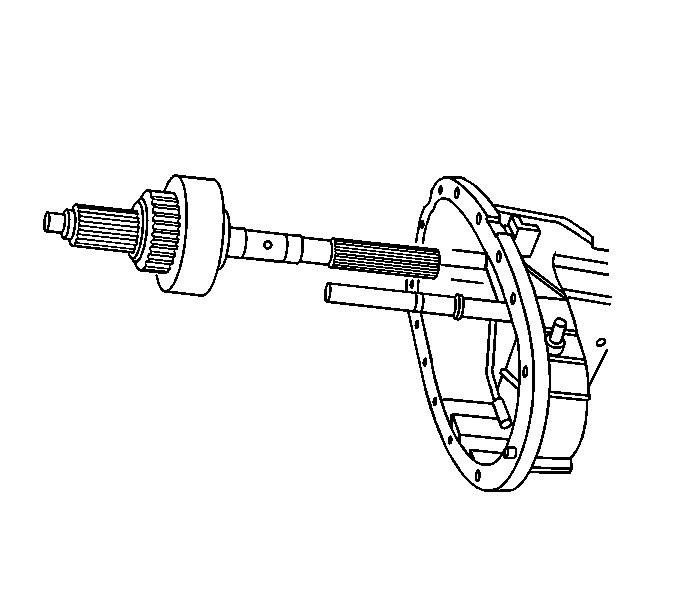
- Working both tools, separate the front input shaft from the front
output shaft bearing, and the input shaft from the output shaft.
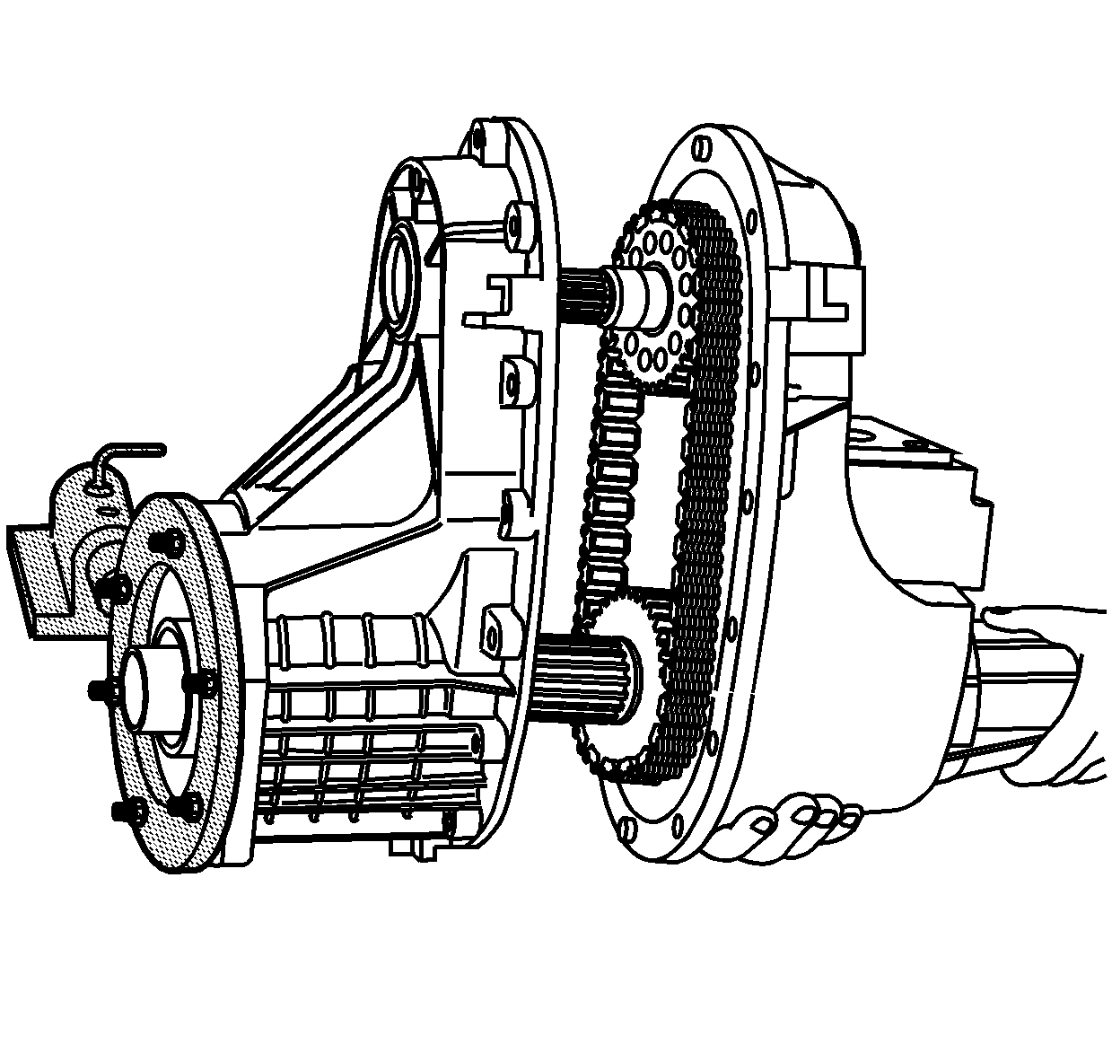
- Remove the rear case
half from the front case half. Only the input gear assembly will remain with
the front case half.
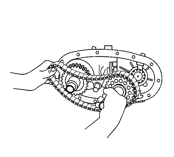
Important: If using the drive chain and sprockets again, mark the position of
the drive chain to the sprockets in order for the proper wear pattern alignment.
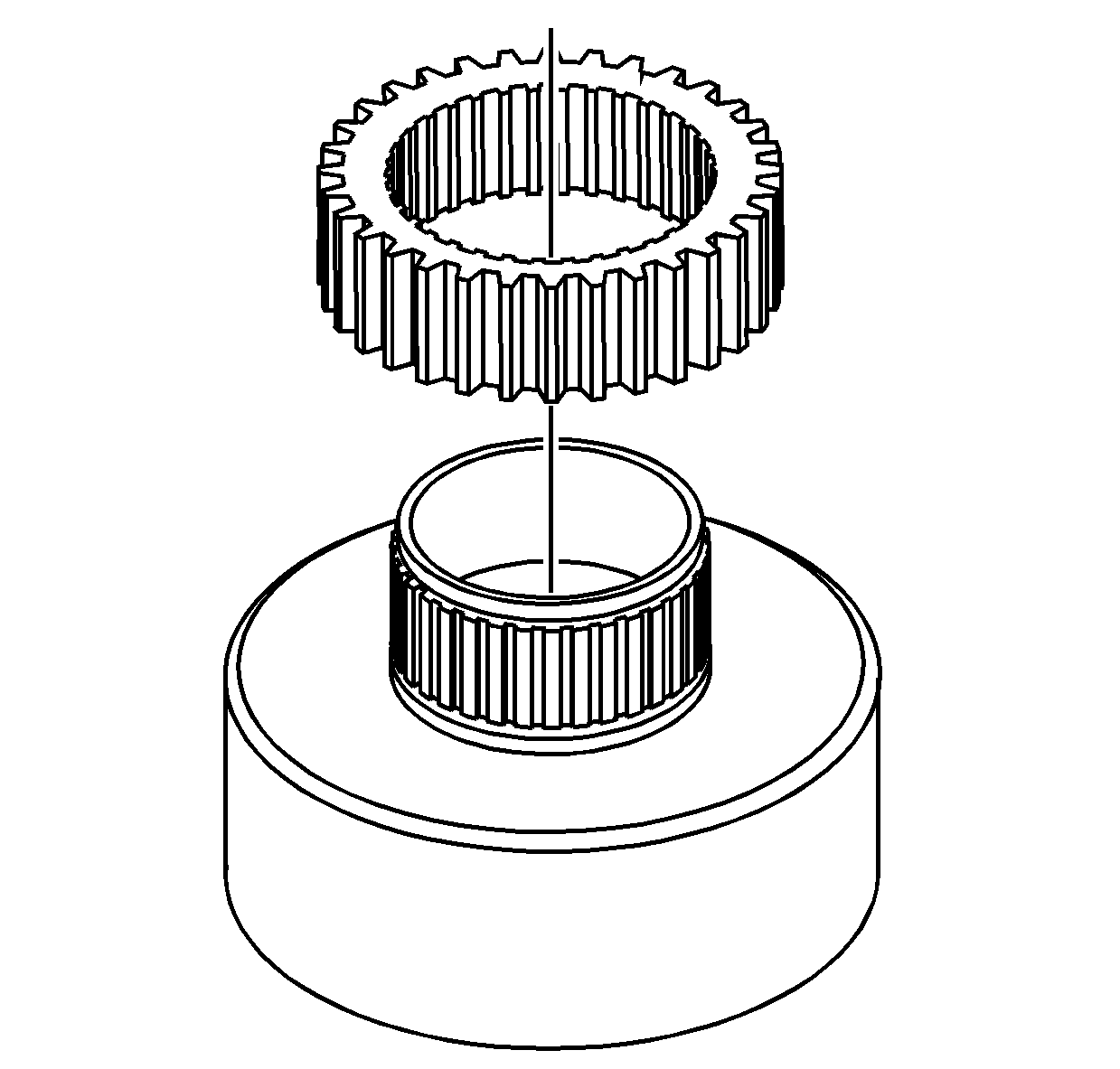
- Remove the front output shaft from the front output shaft rear bearing.
- Remove the drive chain assembly from the drive gear on the output
shaft and the driven gear on the front output shaft.
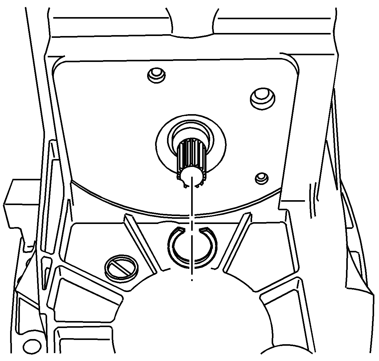
- Remove the retaining ring
for the high/low shift fork.
- Remove the top shift fork
spring.
- Remove the shift fork
assembly from the shift fork shaft.
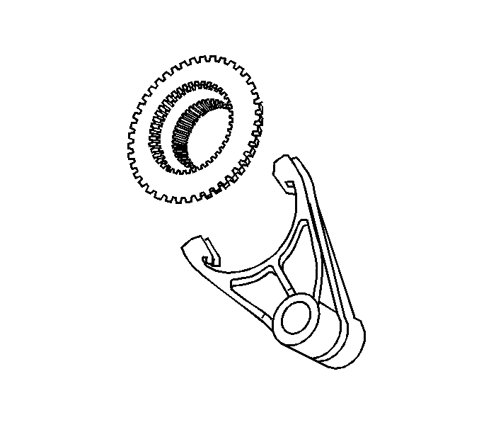
- Separate the shift fork
from the range sleeve.
- Remove the bottom shift
fork spring.
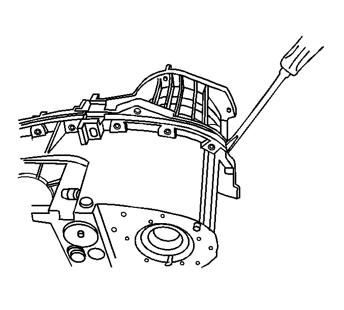
- Insert a screw driver
in the slot of the rear extension.
- Remove the rear extension
from the rear case half.
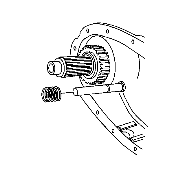
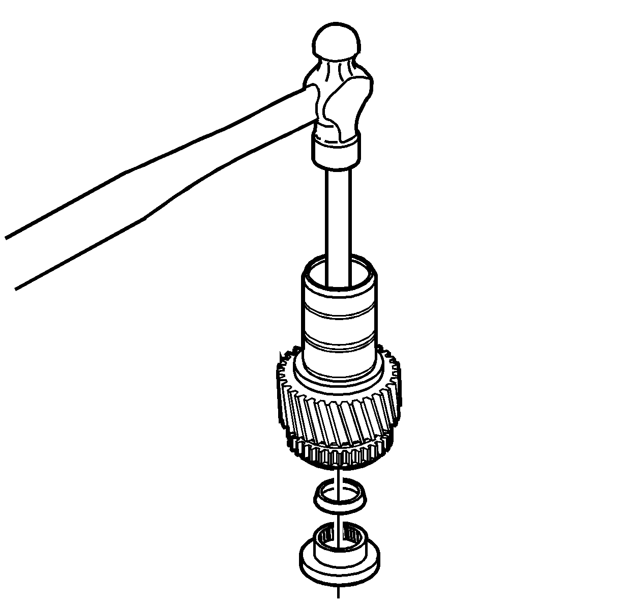
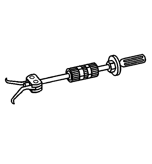
- Using the J 44707
(1), the J 44759
(2), and the J 36513
(3), remove the speed sensor
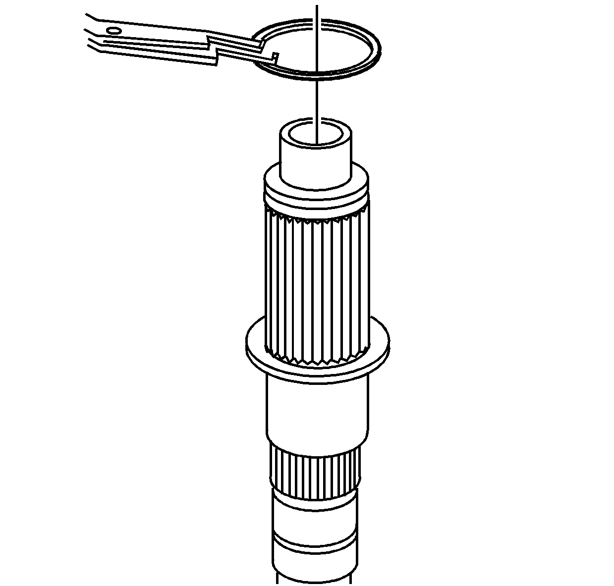
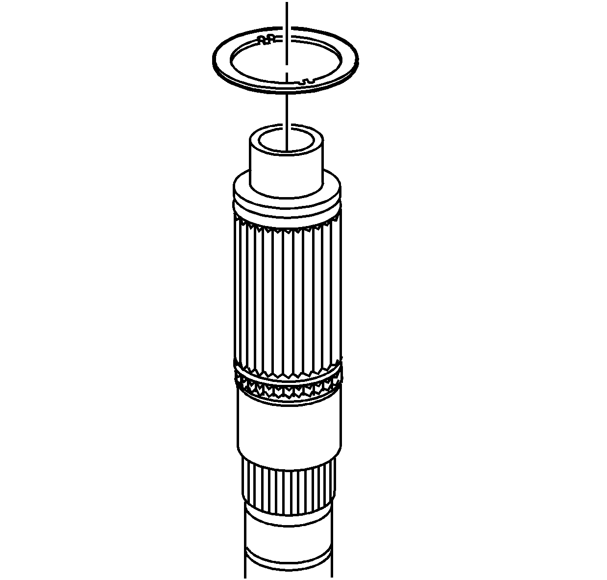
reluctor wheel from the rear output shaft.
- Discard the speed sensor reluctor wheel after removal.
- Remove the rear output
shaft assembly.
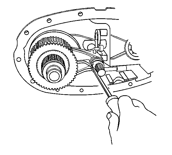
- Remove the clutch lever
from the rear case half.
- Remove the shift fork
shaft with the shift detent lever. Rotate the control actuator lever shaft
in order to remove the shift detent lever.
- Remove the oil pump cover
mounting bolts.
- Remove the oil pump cover.
- Remove the oil pump drive
gear, the inner rotor.
- Remove the oil pump driven gear, the outer rotor.
- While pushing down on
the clutch apply plate, remove the clutch pressure plate bearing retaining
ring.
- Remove the clutch inner
plate.
- Remove the clutch pressure
plate bearing.
- Remove the clutch apply
plate.
- Remove the clutch spring.
- Remove the clutch hub
retaining ring.
- Remove the clutch housing
assembly.
- Hold on to the clutch
plates, and turn the clutch housing over on a workbench.
- Remove the clutch housing from the clutch plates and the clutch
hub.
- Remove the clutch hub from the clutch plates.
- Remove the drive sprocket
retaining ring from the clutch housing.
- Remove the drive sprocket
from the clutch housing.
- Remove the clutch housing
retaining ring from the rear output shaft.
- Remove the rear output
shaft rear thrust washer.
- Using a press, remove
the planetary gear assembly.
| 59.1. | Support the front case half on press plates, to allow the planetary
gear assembly removal. |
| 59.2. | Use a suitable adapter to press on the input gear bearing. |
- Using a press, remove
the input gear bearing.
| 60.1. | Support the planetary gear assembly on press plates, to allow
removal of the input gear. |
| 60.2. | Use a suitable adapter to press on the input gear. |
- Remove the input gear.
- Remove the planetary gear
large diameter thrust washer.
- Remove the input gear
smaller diameter thrust washer.
- If necessary, remove the
bore seal and the input gear thrust bearing from the input gear.
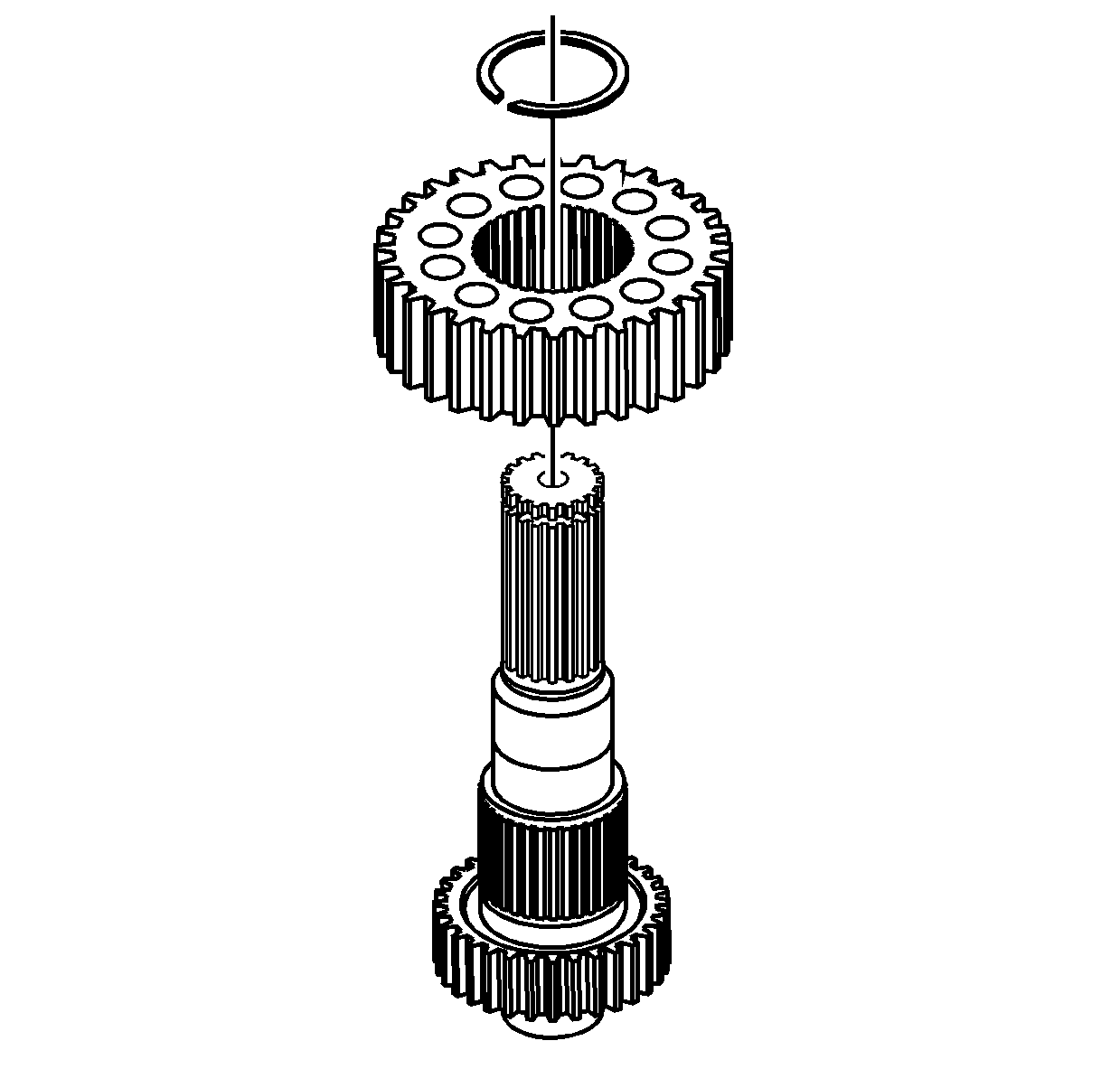
- Remove the driven gear
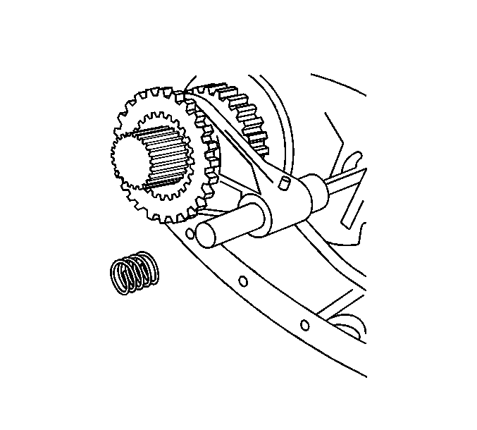
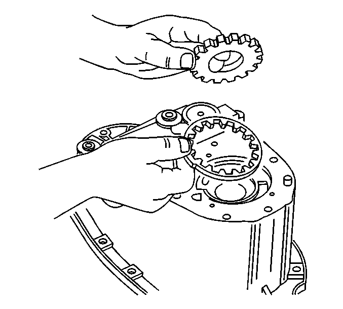
retaining ring from the front output shaft.
- Remove the driven gear from the front output shaft.
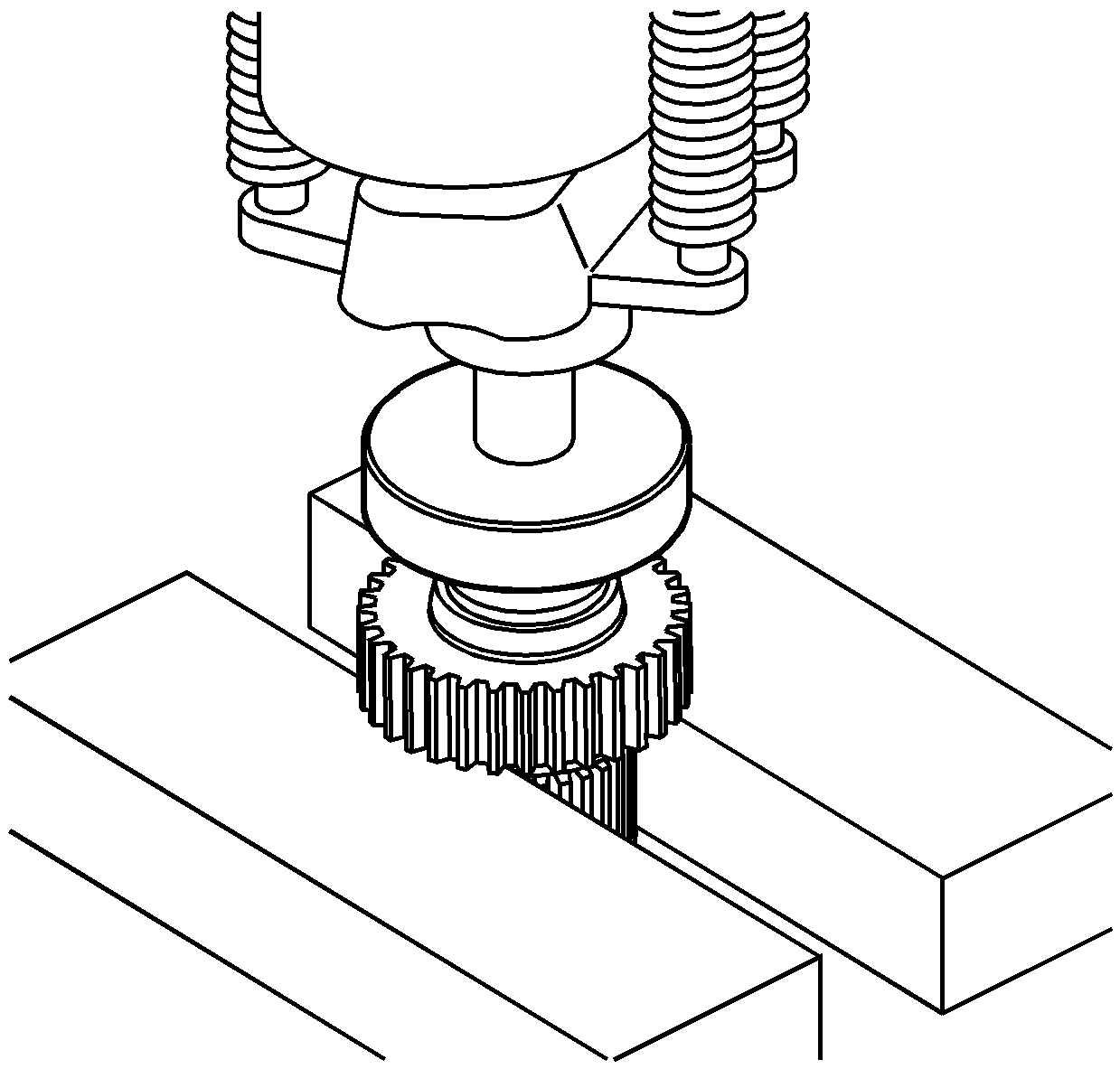
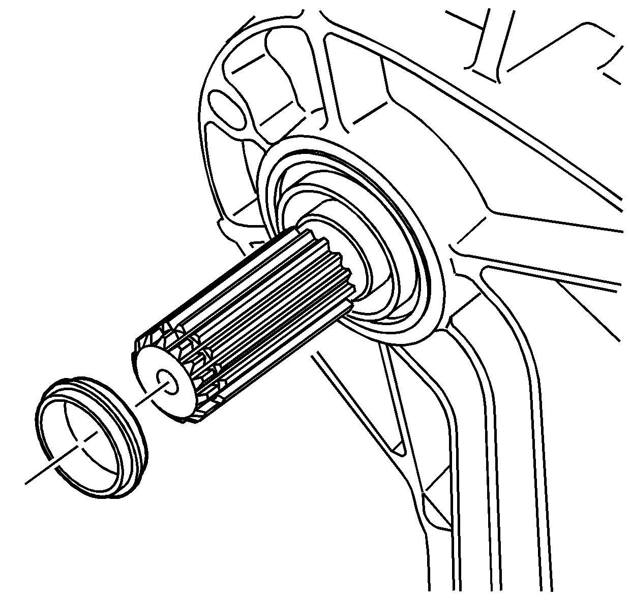
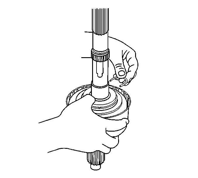
- Using a hydraulic press
and a suitable adapter on the front input shaft, remove the front speed
sensor reluctor wheel.
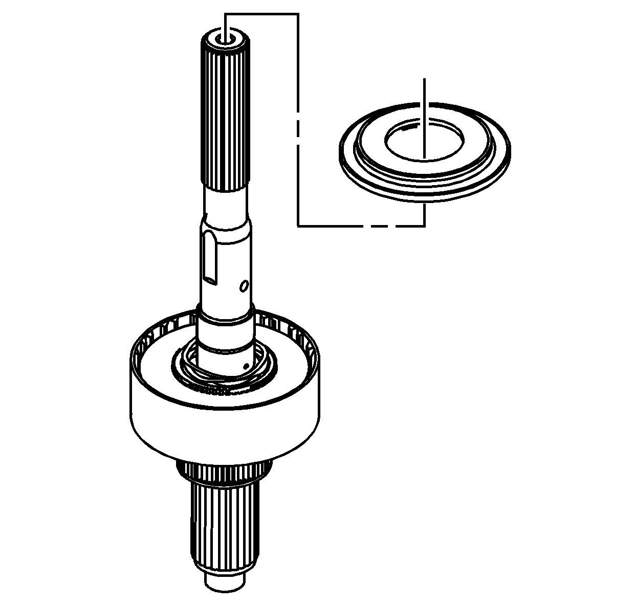
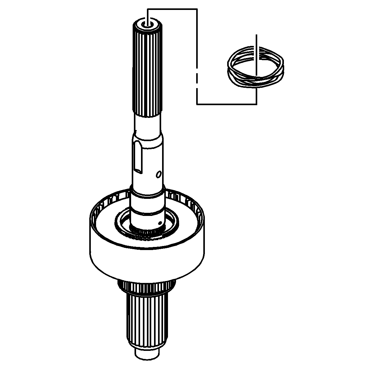
Important: The vent only requires removal if it is damaged.
- Remove the vent.
- Remove the front output
shaft VSS and O-ring seal from the rear case.
- Remove the chip collector
magnet from the rear case.
- Remove the oil pump suction
pipe with the oil pump screen.
- Remove the retaining ring
for the control actuator lever shaft.
- Discard the retaining ring.
- Remove the control actuator
lever shaft from the rear case.
Important: Only remove the bearings if they are faulty. Do not use the bearings
again.
- Inspect the front output shaft rear bearing for being faulty. Refer
to
Transfer Case Cleaning and Inspection
.
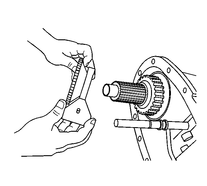
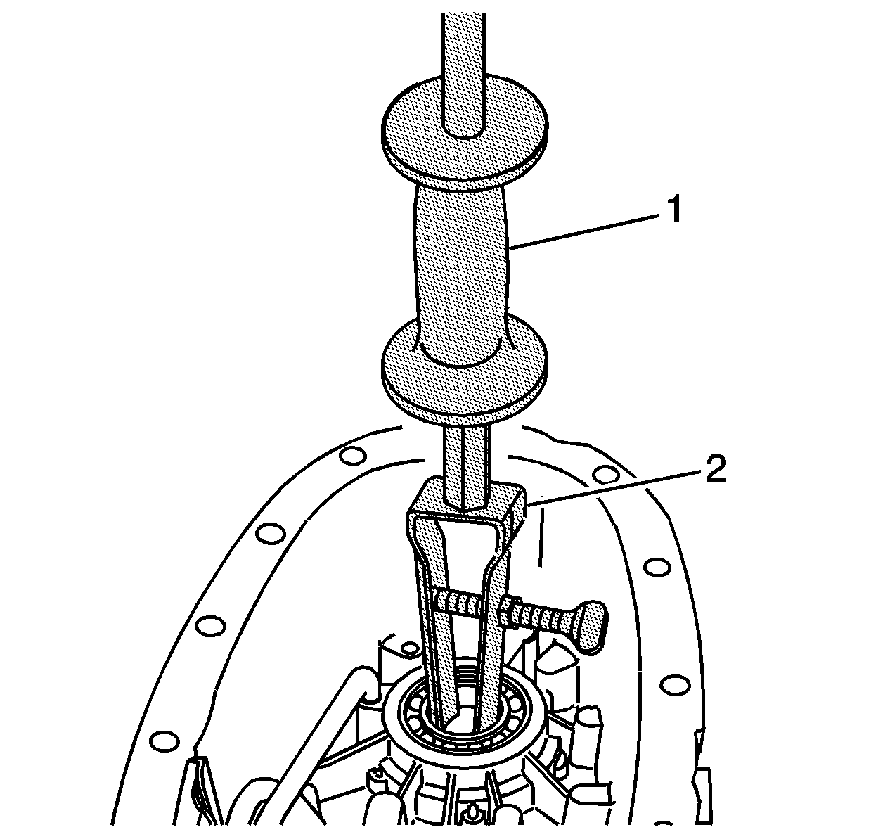
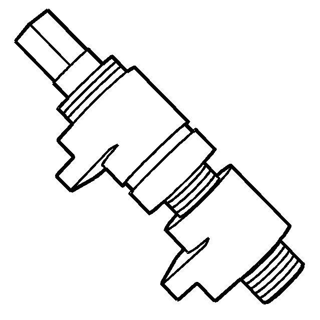
- Using the J 23907
(1) and the J 26941
(2), remove the rear bearing for the front output shaft.
Important: Only remove the bearings if they are faulty. Do not use the bearings
again.
- Inspect the rear output shaft bearing for being faulty. Refer to
Transfer Case Cleaning and Inspection
.
Important: The bushing surface for the oil pump is located by the output shaft
bearing. When using the J 26941
, the jaws must not come in contact with the oil pump bushing surface.
- Using the J 23907
(1)
and the J 26941
(2),
remove the rear output shaft bearing from the rear case. Ensure the jaws
on the J 26941
are between
the bearing and the oil pump bushing.
Important: Only remove the bearings if they are faulty. Do not use the bearings
again.
- Inspect the control actuator lever shaft bearing for being faulty. Refer
to
Transfer Case Cleaning and Inspection
.
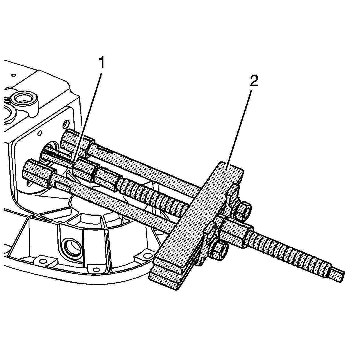
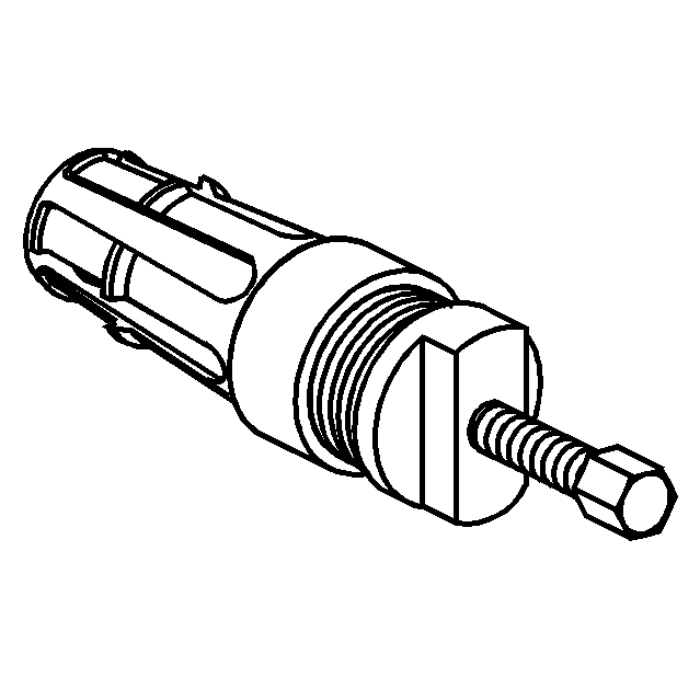
- Using the J 44707
(2) and the J 44737
(1), remove the control actuator lever shaft bearing.
Notice: Refer to Transfer Case Seal Removal Notice in the Preface section.
- Using a suitable prying tool, remove the front output shaft seal.
- Discard the seal.
Important: Only remove the bearings if they are faulty. Do not use the bearings
again.
- Inspect the front output shaft front bearing for being faulty. Refer
to
Transfer Case Cleaning and Inspection
.
- Using a hammer and a punch, remove the front bearing for the front
output shaft from the front case.
- Clean and inspect all the internal parts of the transfer case.
Refer to
Transfer Case Cleaning and Inspection
.
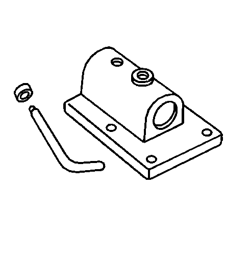
Tools Required
| • | J 23907
Slide Hammer with Bearing Adapter |
| • | J 26941
Bushing and Bearing Remover (3-4 inch) |
| • | J 36513
Gear and Bearing Separator Plate |
| • | J 44737
Shift Rail Bearing Remover |
| • | J 45380
Transfer Case Rear Bushing Remover and Installer |
- If available, using the adapter studs, attach the
J 45759
(2) to the transfer case.
- Mount the
J 3289-20
(1) to a sturdy workbench.
- Install the
J 45759
(2) into the
J 3289-20
(1) and secure with the pivot pin.
- Remove the drain plug.
- Tip the transfer case to remove any remaining transfer case fluid.
Notice: Refer to Transfer Case Seal Removal Notice in the Preface section.
- Using a fine flat-bladed screwdriver and a mallet, loosen the front input shaft seal.
- Using a small block of wood and a large flat-bladed screwdriver, remove the front input shaft seal
from the transfer case.
- Remove the front input shaft seal.
- Remove the dust seal from the front output shaft. The
front output shaft oil seal does not require removal at this time.
- Remove the transfer case bolt that is retaining the wiring harness bracket.
- Mark the location of the wiring harness bracket bolt.
- Remove the encoder/motor mounting bolts.
- Remove the encoder/motor assembly.
- Remove both vehicle speed sensors (VSS) and O-ring seals from the rear
extension.
Notice: Refer to Transfer Case Seal Removal Notice in the Preface section.
- Remove the rear output seal.
- Inspect the rear output shaft bushing for scoring or wear.
- Remove the rear output shaft bushing using the
J 45380
.
| • | Install the finger section of the
J 45380
in front of the bushing. |
| • | Install the tube and forcing screw assembly to the finger section. Ensure the forcing screw is backed out. |
| • | Using a wrench on the forcing screw, remove the rear output shaft bushing. |
Important: Remove the rear extension and case half bolts at the same time for easier rear case disassembly.
- Remove the rear extension mounting bolts.
- Remove the case half bolts.
Notice: Refer to Machined Surface Damage Notice in the Preface section.
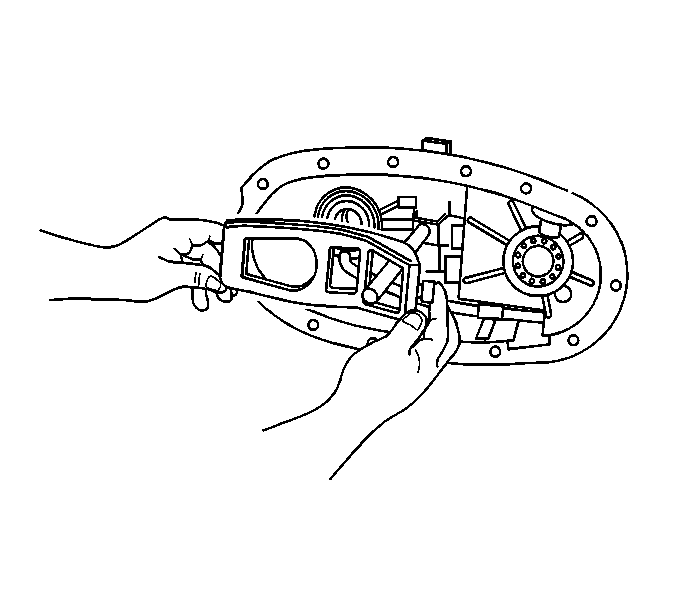
- Install the
J 45358
between the tabs on one side of the case.
Important:
| • | Ensure that all of the case half bolts have been removed. |
| • | DO NOT use screwdrivers or pry bars to separate the transfer case halves. The special tool must be used to separate the transfer case halves properly. |
- Using the
J 45358
, shear the sealer securing the front and rear case half together.
- Move the
J 45358
to the tabs on the other side of the case and shear the sealer.
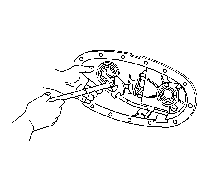
- Use a suitable prying tool at one side of the case half.
- Use a suitable prying tool at the other side of the cased halves.
- Working both tools, separate the front output shaft from the front output shaft bearing, and the input shaft from the output shaft.
- Remove the front case half from the
rear case half. Only the input gear assembly will remain with the front case half.
Important: If using the drive chain and sprockets again, mark the position of the drive chain to the sprockets in order for the proper wear pattern alignment.
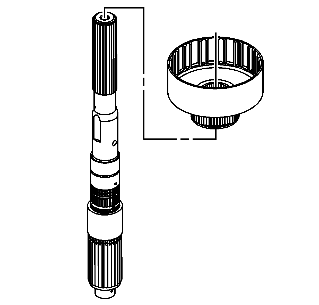
- Remove the front output shaft from the front output shaft rear bearing.
- Remove the drive chain assembly from the drive gear on the output shaft and the driven gear on the front output shaft.
- Remove the retaining ring for the high/low shift fork.
- Remove the top shift fork spring.
- Remove the shift fork assembly from the shift fork shaft.
- Separate the shift fork from the range sleeve.
- Remove the bottom shift fork spring.
- Insert a screwdriver in the slot of the rear extension.
- Remove the rear extension from the rear case half.
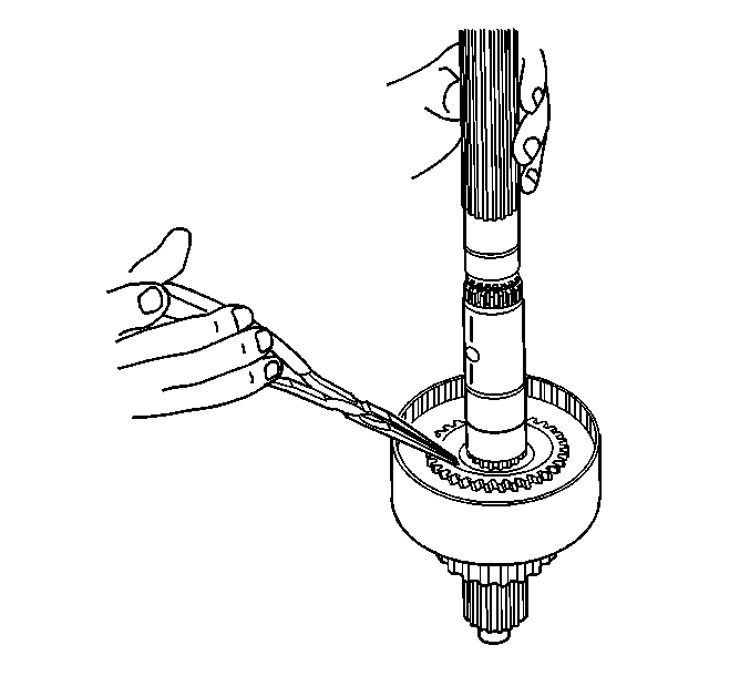
- Using the
J 44707
(1), the
J 44759
(2), and the
J 36513
(3), remove the speed sensor reluctor wheel from the rear output shaft.
- Discard the speed sensor reluctor wheel after removal.
- Remove the rear output shaft assembly.
- Remove the clutch lever from the rear case half.
- Remove the shift fork shaft with the shift detent lever. Rotate the control actuator lever shaft in order
to remove the shift detent lever.
- Remove the oil pump cover mounting bolts.
- Remove the oil pump cover.
- Remove the oil pump drive gear, the inner rotor.
- Remove the oil pump driven gear, the outer rotor.
- While pushing down on the clutch apply plate, remove the clutch pressure plate bearing retaining ring.
- Remove the clutch inner plate.
- Remove the clutch pressure plate bearing.
- Remove the clutch apply plate.
- Remove the clutch spring.
- Remove the clutch hub retaining ring.
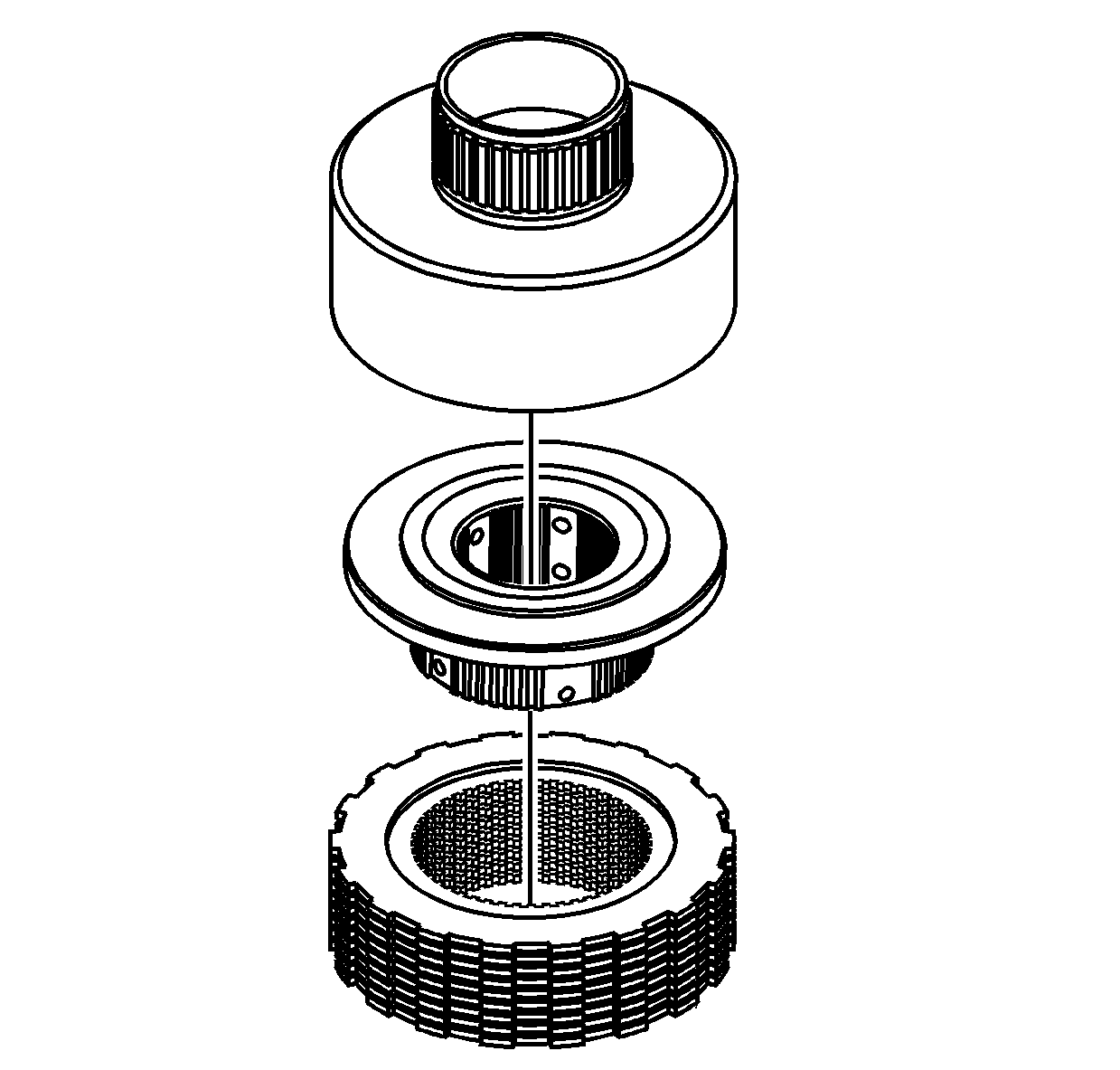
- Remove the clutch housing assembly.
- Hold on to the clutch plates, and turn the clutch housing over on a workbench.
- Remove the clutch housing from the clutch plates and the clutch hub.
- Remove the clutch hub from the clutch plates.
- Remove the drive sprocket retaining ring from the clutch
housing.
- Remove the drive sprocket from the clutch housing.
- Remove the clutch housing retaining ring from the rear output shaft.
- Remove the rear output shaft rear thrust washer.
- Using a press, remove the planetary gear assembly.
| 59.1. | Support the front case half on press plates, to allow the planetary gear assembly removal. |
| 59.2. | Use a suitable adapter to press on the input gear bearing. |
- Using a press, remove the input gear bearing.
| 60.1. | Support the planetary gear assembly on press plates, to allow removal of the input gear. |
| 60.2. | Use a suitable adapter to press on the input gear. |
- Remove the input gear.
- Remove the planetary gear large diameter thrust washer.
- Remove the input gear smaller diameter thrust washer.
- If necessary, remove the bore seal
and the input gear thrust bearing from the input gear.
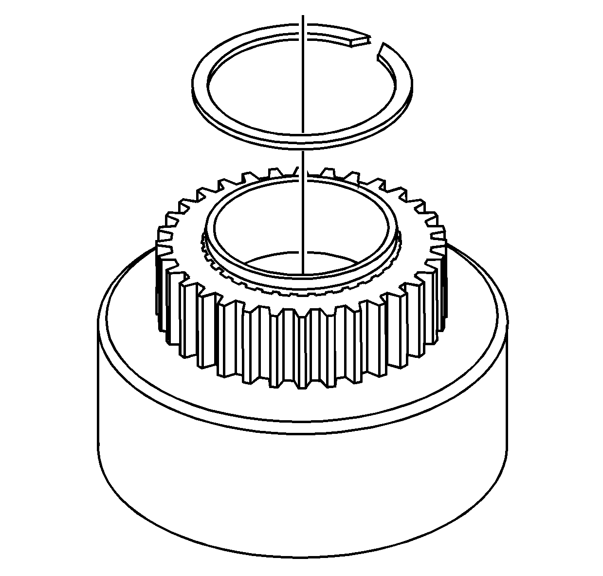
- Remove the driven gear retaining ring from the front
output shaft.
- Remove the driven gear from the front output shaft.
- Using a hydraulic press and a suitable adapter on the
front input shaft, remove the front speed sensor reluctor wheel.
Important: The vent only requires removal if it is damaged.
- Remove the vent.
- Remove the front output shaft VSS and O-ring
seal from the rear case.
- Remove the chip collector magnet from the rear case.
- Remove the oil pump suction pipe with the oil pump screen.
- Remove the retaining ring for the control
actuator lever shaft.
- Discard the retaining ring.
- Remove the control actuator lever shaft from the rear
case.
Important: Only remove the bearings if they are faulty. Do not use the bearings again.
- Inspect the front output shaft rear bearing for being faulty. Refer to
Transfer Case Cleaning and Inspection.
- Using the
J 23907
(1) and the
J 26941
(2), remove the rear bearing for the front output shaft.
Important: Only remove the bearings if they are faulty. Do not use the bearings again.
- Inspect the rear output shaft bearing for being faulty. Refer to
Transfer Case Cleaning and Inspection.
Important: The bushing surface for the oil pump is located by the output shaft bearing. When using the
J 26941
, the jaws must not come in contact with the oil pump bushing surface.
- Using the
J 23907
(1) and the
J 26941
(2), remove the rear output shaft bearing from the rear case. Ensure the jaws on the
J 26941
are between the bearing and the oil pump bushing.
Important: Only remove the bearings if they are faulty. Do not use the bearings again.
- Inspect the control actuator lever shaft bearing for being faulty. Refer to
Transfer Case Cleaning and Inspection.
- Using the
J 44707
(2) and the
J 44737
(1), remove the control actuator lever shaft bearing.
Notice: Refer to Transfer Case Seal Removal Notice in the Preface section.
- Using a suitable prying tool, remove the front output shaft seal.
- Discard the seal.
Important: Only remove the bearings if they are faulty. Do not use the bearings again.
- Inspect the front output shaft front bearing for being faulty. Refer to
Transfer Case Cleaning and Inspection.
- Using a hammer and a punch, remove the front bearing for the front output shaft from the front case.
- Clean and inspect all the internal parts of the transfer case. Refer to
Transfer Case Cleaning and Inspection.
