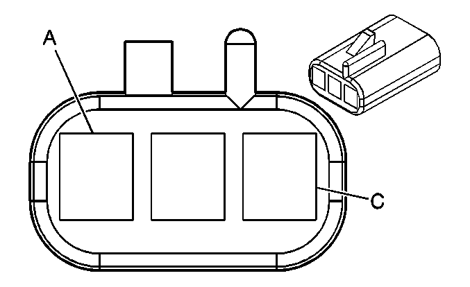
| |||||||
|---|---|---|---|---|---|---|---|
Connector Part Information |
| ||||||
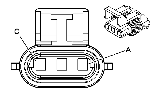
Pin | Wire Color | Circuit No. | Function | ||||
A | BK | 350 | Ground | ||||
B | D-GN | 59 | A/C Compressor Clutch Supply Voltage | ||||
C | L-GN | 2278 | A/C Compressor Status Signal | ||||
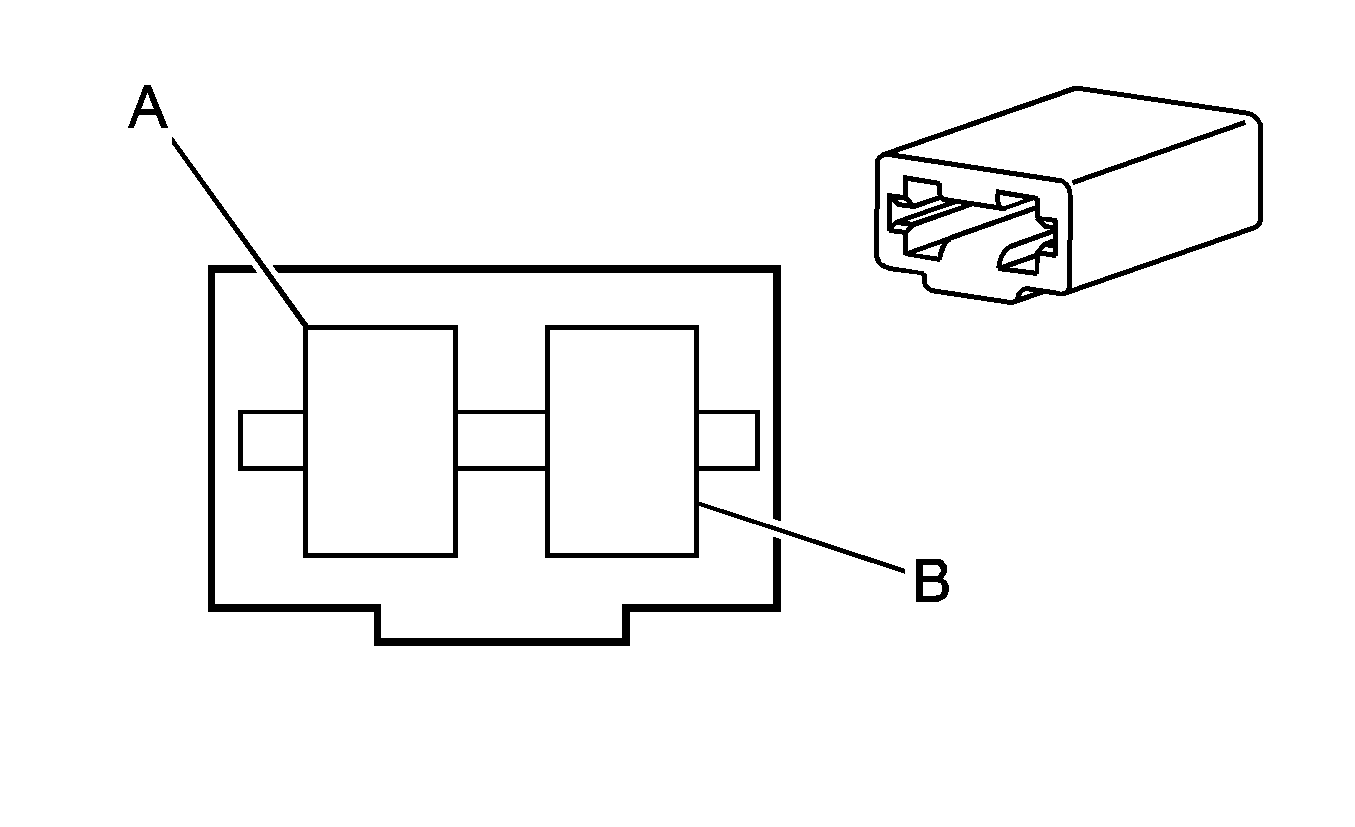
| |||||||
|---|---|---|---|---|---|---|---|
Connector Part Information |
| ||||||
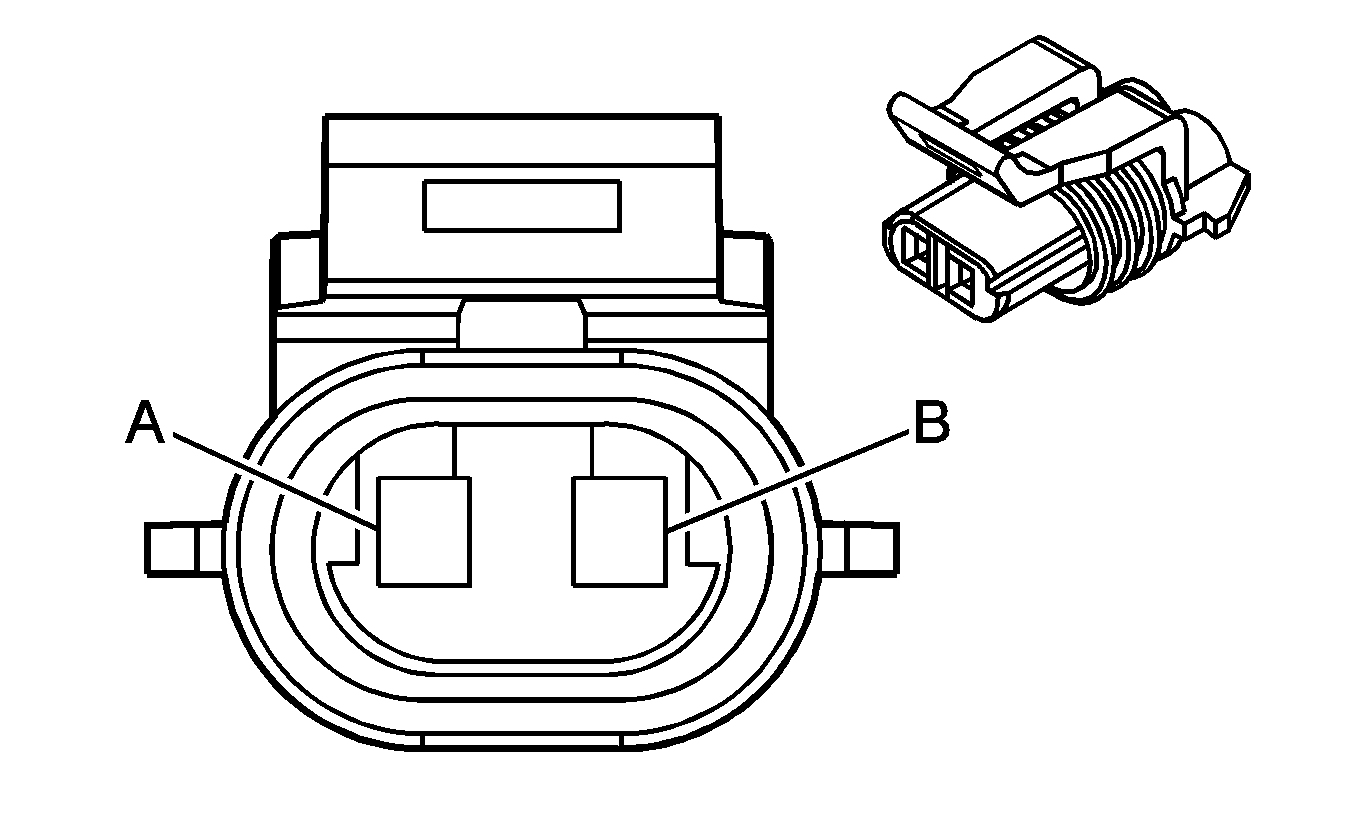
Pin | Wire Color | Circuit No. | Function | ||||
A | D-BU | 204 | A/C Low Pressure Sensor Signal | ||||
B | BK | 250 | Ground | ||||
| |||||||
|---|---|---|---|---|---|---|---|
Connector Part Information |
| ||||||
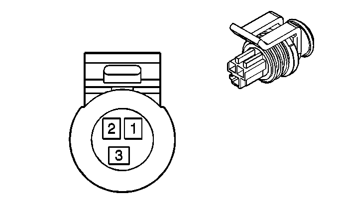
Pin | Wire Color | Circuit No. | Function | ||||
1 | BK | 2751 | Low Reference | ||||
2 | GY | 2700 | 5-Volt Reference | ||||
3 | RD/BK | 380 | A/C Refrigerant Pressure Sensor Signal | ||||
| |||||||
|---|---|---|---|---|---|---|---|
Connector Part Information |
| ||||||
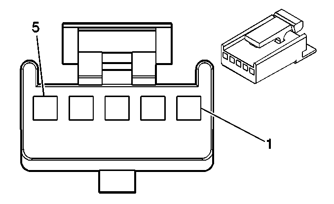
Pin | Wire Color | Circuit No. | Function | ||||
1 | GY | 2598 | Low Reference | ||||
2 | D-BU | 1199 | Auxiliary Air Temperature Door Position Signal | ||||
3 | GY/BK | 598 | 5-Volt Reference | ||||
4 | RD | 2600 | Auxiliary Actuator Door Control | ||||
5 | YE | 2214 | Auxiliary Air Temperature Door Control | ||||
| |||||||
|---|---|---|---|---|---|---|---|
Connector Part Information |
| ||||||
Pin | Wire Color | Circuit No. | Function | ||||
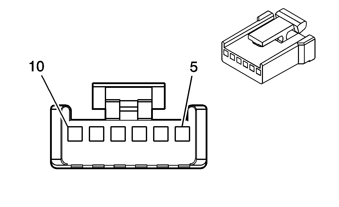
5 | BN | 341 | Ignition 3 Voltage | ||||
6 | D-BU | 1199 | Left Air Temperature Door Control | ||||
7 | YE | 1791 | Low Reference | ||||
8 | -- | -- | Not Used | ||||
9 | L-BU | 733 | Left Air Temperature Door Position Signal | ||||
10 | L-BU/BK | 1688 | 5-Volt Reference | ||||
|
| |||||||
|---|---|---|---|---|---|---|---|
Connector Part Information |
| ||||||
Pin | Wire Color | Circuit No. | Function | ||||
5 | BN | 341 | Ignition 3 Voltage | ||||
6 | WH/BK | 1236 | Right Air Temperature Door Control | ||||
7 | YE | 1791 | Low Reference | ||||
8 | -- | -- | Not Used | ||||
9 | D-BU | 1646 | Right Air Temperature Door Position Signal | ||||
10 | L-BU/BK | 1688 | 5-Volt Reference | ||||
| |||||||
|---|---|---|---|---|---|---|---|
Connector Part Information |
| ||||||
Pin | Wire Color | Circuit No. | Function | ||||
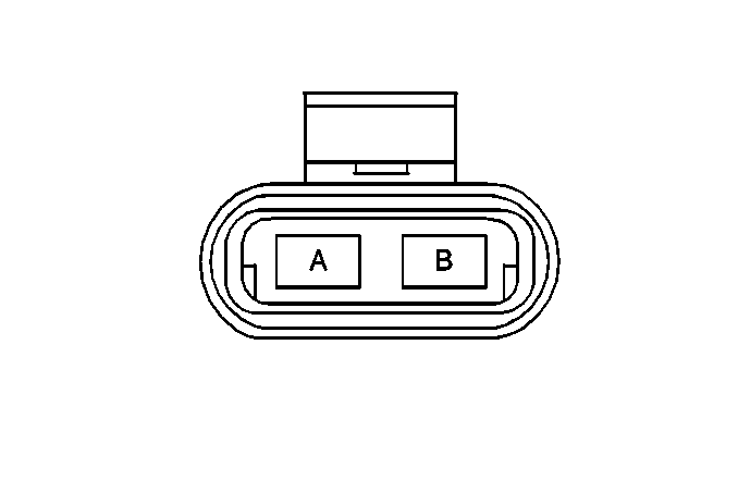
A | PU | 65 | Blower Motor Supply Voltage | ||||
B | BK | 850 | Ground | ||||
| |||||||
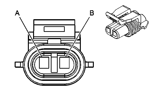
|---|---|---|---|---|---|---|---|
Connector Part Information |
| ||||||
Pin | Wire Color | Circuit No. | Function | ||||
A | OG | 840 | Battery Positive Voltage | ||||
B | BK | 250 | Ground | ||||
| |||||||
|---|---|---|---|---|---|---|---|
Connector Part Information |
| ||||||
Pin | Wire Color | Circuit No. | Function | ||||
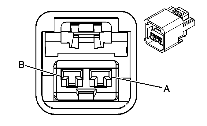
A | BK | 1650 | Ground | ||||
B | BK | 250 | Ground | ||||
C | GY | 2604 | Auxiliary Blower Motor Speed Control | ||||
D | OG | 840 | Battery Positive Voltage | ||||
| |||||||
|---|---|---|---|---|---|---|---|
Connector Part Information |
| ||||||
Pin | Wire Color | Circuit No. | Function | ||||
A | OG | 840 | Battery Positive Voltage | ||||
B | OG | 840 | Battery Positive Voltage | ||||
OG | 840 | Battery Positive Voltage | |||||
| |||||||
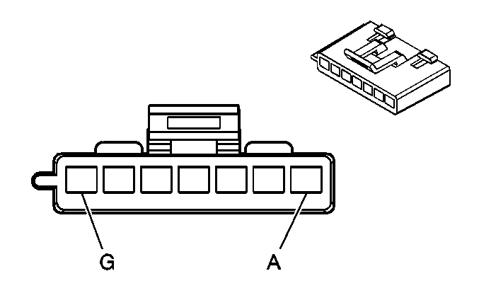
|---|---|---|---|---|---|---|---|
Connector Part Information |
| ||||||
Pin | Wire Color | Circuit No. | Function | ||||
A | TN | 63 | Medium 1 Blower Motor Control | ||||
B | YE | 60 | Low Blower Motor Control | ||||
C | PU | 73 | Medium 3 Blower Motor Control | ||||
D | L-BU | 72 | Medium 2 Blower Motor Control | ||||
E | BK | 2250 | Ground | ||||
F | OG | 52 | High Blower Motor Control | ||||
G | RD | 542 | Battery Positive Voltage | ||||
| |||||||
|---|---|---|---|---|---|---|---|
Connector Part Information |
| ||||||
Pin | Wire Color | Circuit No. | Function | ||||
A | YE | 2277 | Auxiliary HVAC Enable Control | ||||
B | GY | 2598 | Low Reference | ||||
C | BN/WH | 230 | Instrument Panel Lamps Dimming Control | ||||
|
| |||||||
|---|---|---|---|---|---|---|---|
Connector Part Information |
| ||||||
Pin | Wire Color | Circuit No. | Function | ||||
1 | GY | 2598 | Low Reference | ||||
2 | L-BU | 5433 | Console Mode Door Position Signal | ||||
3 | GY | 598 | 5-Volt Reference | ||||
4 | GY | 2599 | Auxiliary Mode Door Control | ||||
5 | L-GN | 5434 | Console Mode Door Control | ||||
| |||||||
|---|---|---|---|---|---|---|---|
Connector Part Information |
| ||||||
Pin | Wire Color | Circuit No. | Function | ||||
A | GY/BK | 1596 | Coolant Bypass Solenoid Control | ||||
B | BK | 250 | Ground | ||||
|
| |||||||
|---|---|---|---|---|---|---|---|
Connector Part Information |
| ||||||
Pin | Wire Color | Circuit No. | Function | ||||
5 | BN | 341 | Ignition 3 Voltage | ||||
6 | TN/BK | 2274 | Defrost Door Control | ||||
7 | YE | 1791 | Low Reference | ||||
8 | -- | -- | Not Used | ||||
9 | L-GN/BK | 2276 | Defrost Door Position Signal | ||||
10 | L-BU/BK | 1688 | 5-Volt Reference | ||||
| |||||||
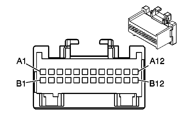
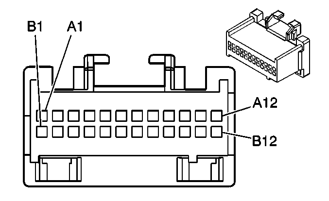
|---|---|---|---|---|---|---|---|
Connector Part Information |
| ||||||
Pin | Wire Color | Circuit No. | Function | ||||
A1 | D-GN | 1614 | Recirculation Door Control | ||||
A2 | D-BU | 1646 | Right Air Temperature Door Position Signal | ||||
A3 | L-BU | 733 | Left Air Temperature Door Position Signal | ||||
A4 | L-GN/BK | 2276 | Defrost Door Position Signal | ||||
A5 | L-GN | 2275 | Mode Door Position Signal | ||||
A6 | -- | -- | Not Used | ||||
A7 | BN/WH | 230 | Instrument Panel Lamps Dimming Control | ||||
A8 | BK/WH | 751 | Ground | ||||
A9 | GY/BK | 1596 | Coolant Bypass Solenoid Control (Long Wheelbase) | ||||
A10 | YE | 2277 | Auxiliary HVAC Enable Control | ||||
A11 | D-GN | 71 | OFF Blower Motor Control | ||||
A12 | D-BU | 204 | A/C Low Pressure Sensor Signal | ||||
B1 | WH/BK | 1236 | Right Air Temperature Door Control | ||||
B2 | D-BU | 1199 | Left Air Temperature Door Control | ||||
B3 | TN/BK | 2274 | Defrost Door Control | ||||
B4 | TN | 2273 | Mode Door Control | ||||
B5 | BN | 341 | Ignition 3 Voltage | ||||
B6 | YE | 1791 | Low Reference | ||||
B7 | OG | 4340 | Battery Positive Voltage | ||||
B8 | L-BU/BK | 1688 | 5-Volt Reference | ||||
B9 | BK | 2250 | Ground | ||||
B10 | -- | -- | Not Used | ||||
B11 | WH | 1038 | HVAC Class 2 Serial Data | ||||
B12 | L-GN | 2278 | A/C Compressor Status Signal | ||||
| |||||||
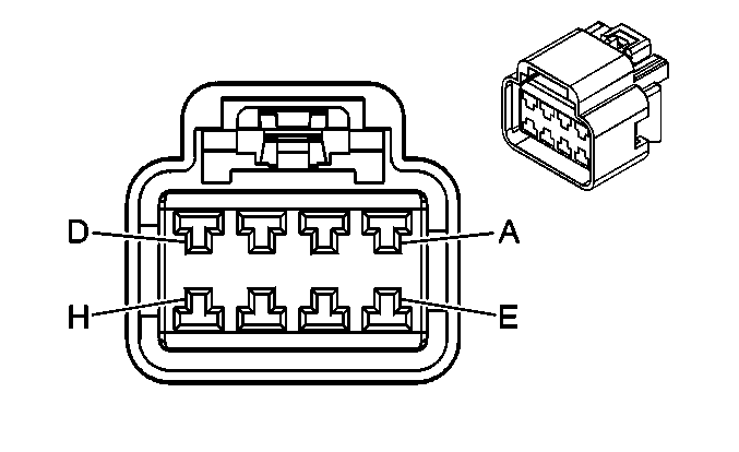
|---|---|---|---|---|---|---|---|
Connector Part Information |
| ||||||
Pin | Wire Color | Circuit No. | Function | ||||
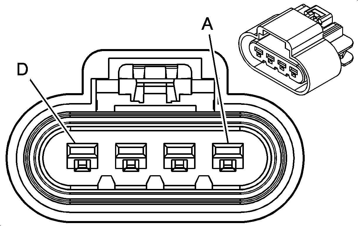
A | PU | 73 | Medium 3 Blower Motor Control | ||||
B | L-BU | 72 | Medium 2 Blower Motor Control | ||||
C | TN | 63 | Medium 1 Blower Motor Control | ||||
D | YE | 60 | Low Blower Motor Control | ||||
E | -- | -- | Not Used | ||||
F | OG | 52 | High Blower Motor Control | ||||
G | BN | 141 | Ignition 3 Voltage | ||||
H | D-GN | 71 | OFF Blower Motor Control | ||||
| |||||||
|---|---|---|---|---|---|---|---|
Connector Part Information |
| ||||||
Pin | Wire Color | Circuit No. | Function | ||||
1 | BN | 341 | Ignition 3 Voltage | ||||
2-3 | -- | -- | Not Used | ||||
4 | YE | 2277 | Auxiliary HVAC Enable Control | ||||
5 | -- | -- | Not Used | ||||
6 | WH | 119 | Auxiliary Mode Door Control | ||||
7 | BK | 2250 | Ground | ||||
8 | BN/WH | 230 | Instrument Panel Lamps Dimming Control | ||||
| |||||||
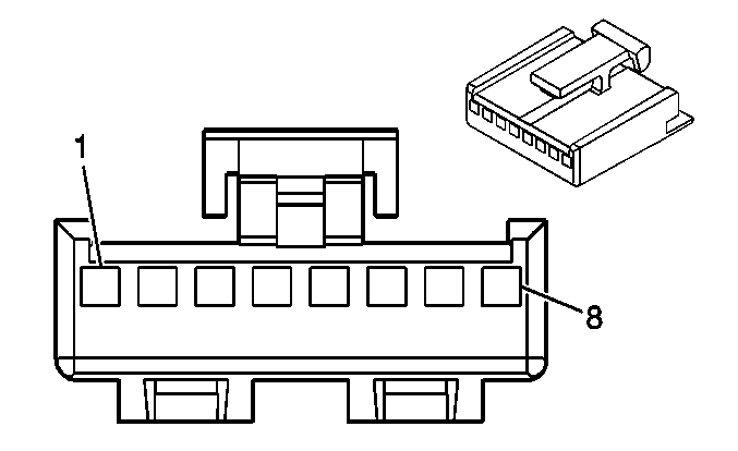
|---|---|---|---|---|---|---|---|
Connector Part Information |
| ||||||
Pin | Wire Color | Circuit No. | Function | ||||
A1 | BN/WH | 230 | Instrument Panel Lamps Dimming Control | ||||
A2 | OG | 4340 | Battery Positive Voltage | ||||
A3 | GY | 2603 | TXV Solenoid Control | ||||
A4 | GY | 2599 | Auxiliary Mode Door Control | ||||
A5 | RD | 2600 | Auxiliary Actuator Door Control | ||||
A6 | YE | 2277 | Auxiliary HVAC Enable Control | ||||
A7 | D-BU | 1199 | Auxiliary Air Temperature Door Position Signal | ||||
A8 | L-BU | 5433 | Console Mode Door Position Signal | ||||
A9 | GY | 598 | 5-Volt Reference | ||||
A10 | -- | -- | Not Used | ||||
A11 | GY | 2289 | Rear HVAC/Audio Class 2 Serial Data | ||||
A12 | -- | -- | Not Used | ||||
B1 | BK | 2250 | Ground | ||||
B2 | GY | 2598 | Low Reference | ||||
B3 | YE | 2214 | Auxiliary Air Temperature Door Control | ||||
B4 | L-GN | 5434 | Console Mode Door Control | ||||
B5 | BN/WH | 2601 | Auxiliary Mode Door Position Signal | ||||
B6-B11 | -- | -- | Not Used | ||||
B12 | GY | 2604 | Auxiliary Blower Motor Speed Control | ||||
|
| |||||||
|---|---|---|---|---|---|---|---|
Connector Part Information |
| ||||||
Pin | Wire Color | Circuit No. | Function | ||||
5 | BN | 341 | Ignition 3 Voltage | ||||
6 | TN | 2273 | Mode Door Control | ||||
7 | YE | 1791 | Low Reference | ||||
8 | -- | -- | Not Used | ||||
9 | L-GN | 2275 | Mode Door Position Signal | ||||
10 | L-BU/BK | 1688 | 5-Volt Reference | ||||
|
| |||||||
|---|---|---|---|---|---|---|---|
Connector Part Information |
| ||||||
Pin | Wire Color | Circuit No. | Function | ||||
1 | BN | 341 | Ignition 3 Voltage | ||||
2 | WH | 119 | Auxiliary Mode Door Control | ||||
3 | BK | 2250 | Ground | ||||
4-5 | -- | -- | Not Used | ||||
|
| |||||||
|---|---|---|---|---|---|---|---|
Connector Part Information |
| ||||||
Pin | Wire Color | Circuit No. | Function | ||||
1 | GY | 2598 | Low Reference | ||||
2 | BN/WH | 2601 | Auxiliary Mode Door Position Signal | ||||
3 | GY/BK | 598 | 5-Volt Reference | ||||
4 | RD | 2600 | Auxiliary Actuator Door Control | ||||
5 | GY/WH | 2599 | Auxiliary Mode Door Control | ||||
|
| |||||||
|---|---|---|---|---|---|---|---|
Connector Part Information |
| ||||||
Pin | Wire Color | Circuit No. | Function | ||||
5 | BN | 341 | Ignition 3 Voltage | ||||
6 | D-GN | 1614 | Recirculation Door Control | ||||
7 | BK | 2250 | Ground | ||||
8-10 | -- | -- | Not Used | ||||
