Tools Required
| • | J 8105 Gear Puller |
| • | J 21427-A Speedometer Gear Puller Adapter |
| • | J 22912-01 Separator Plate |
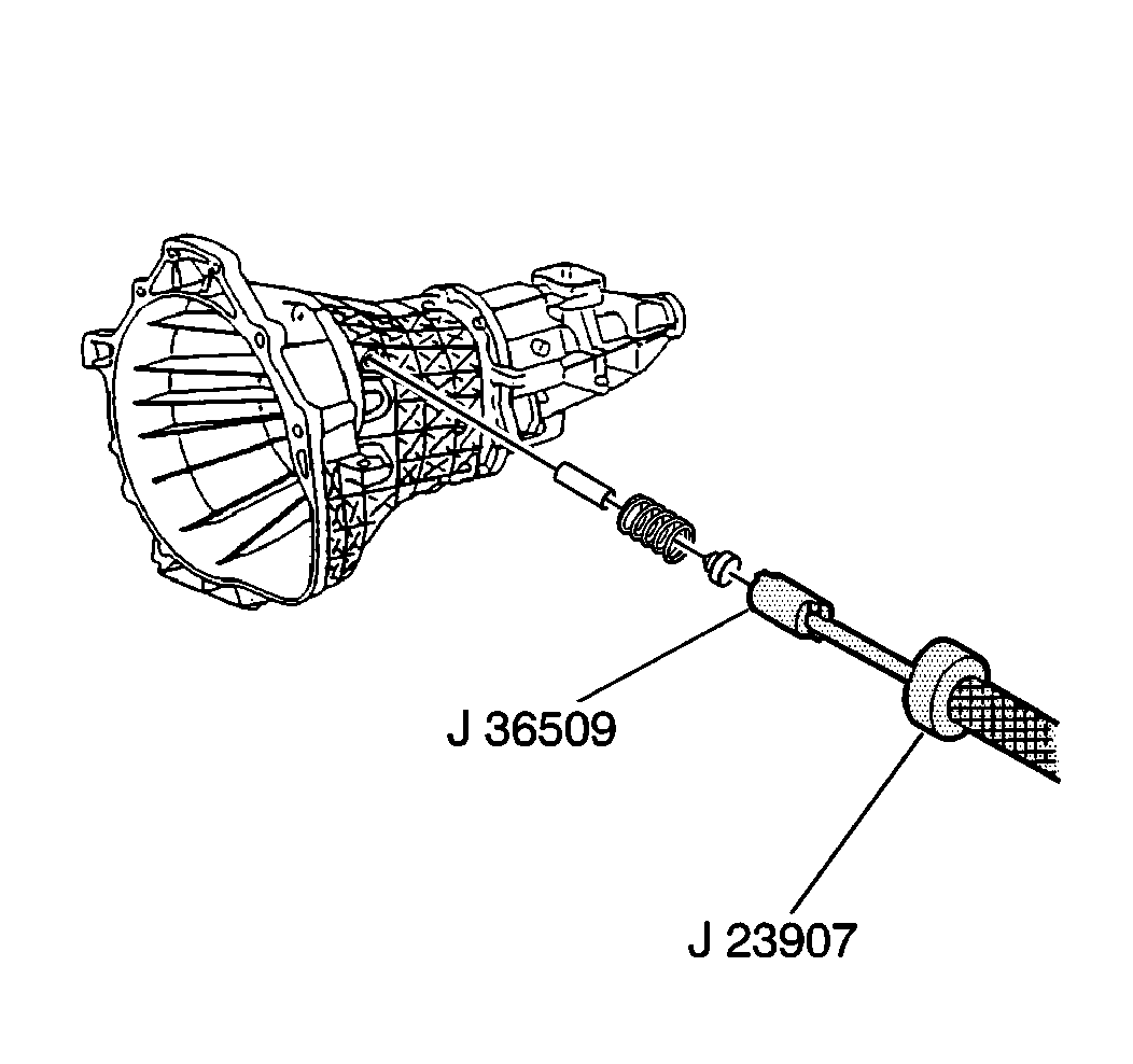
| • | J 23907 Slide Hammer and Adaptor |
| • | J 36509 Detent Spring Plug Remover |
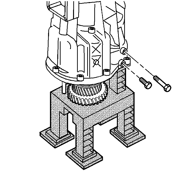
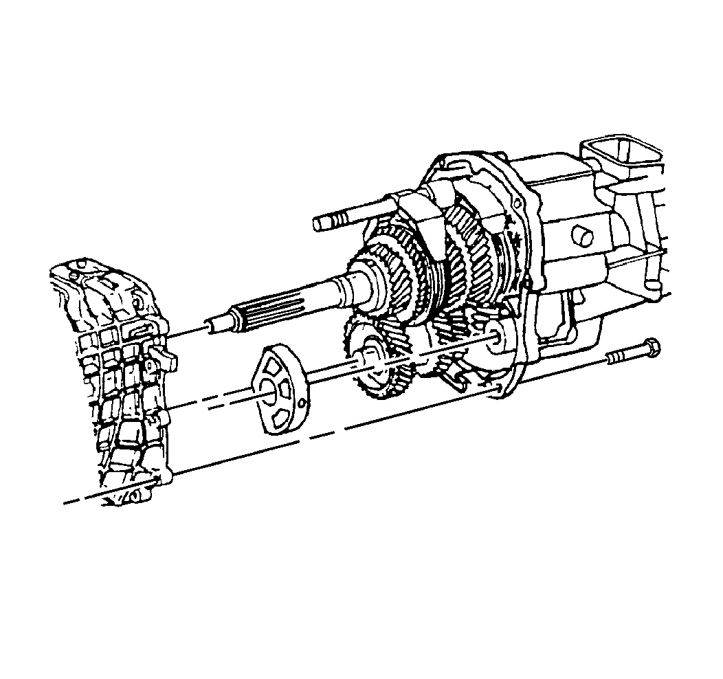
- Remove the two bolts which attach the idler shaft segment and the idler shaft support collar to the rear housing.
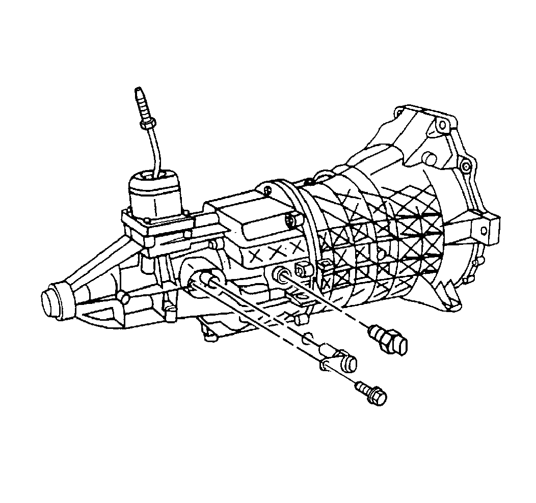
- Remove the backup lamp switch from the rear housing.
- Remove the bolt and the electronic speed sensor from the rear housing.
- Remove the shift shaft block-out bushing pin from the front housing.
- Use the J 36509 and the J 23907 in order to remove the following components from the front housing:
- Slide the hammer with the 6 mm end into the hole in the front housing.
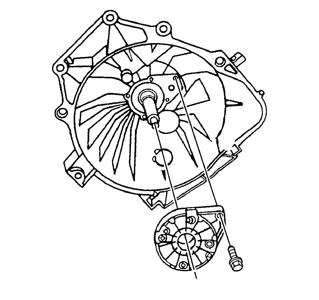
- Remove the five bolts which secure the input shaft bearing retainer to the front housing.
- Use the J 23907 to remove the input shaft bearing retainer from the front housing.
- Remove the snap ring.
- Remove the nine bolts which attach the front housing to the rear housing.
- Angle the front housing up and press down on the rear housing in order to separate the front housing from the rear housing.
- Remove the countershaft roller bearing from the countershaft or the bearing shell.
- Remove the shift shaft lever roll pin from the shift shaft lever:
- Remove the shift shaft socket roll pin from the bottom of the shift shaft socket.
- Remove the following components:
- Rotate the third-fourth shift fork counterclockwise.
- Remove the five bolts which secure the output shaft bearing retainer to the center of the rear housing.
- Remove the rear housing from the gear assemblies.
- Remove the reverse idler gear assembly.
- Remove the output shaft bearing retainer.
- Remove the shift forks.
- Remove the countershaft.
- Remove the countershaft bearing snap ring.
- Remove the countershaft bearing.
- Remove the fifth counter gear from the counter shaft.
- Use the J 21427-A and the J 8105 to remove the speed sensor rotor from the output shaft.
- Remove the snap ring from the output shaft.
- Use the J 21427-A and the J 8105 to remove the output shaft bearing from the output shaft.
- Remove the fifth speed gear from the output shaft.
- Remove the snap ring from the output shaft.
- Remove the following components from the output shaft:
- Leave the synchronizer rings on the fifth-reverse synchronizer assembly in order to prevent the synchronizer detent balls from popping out.
- Remove the input shaft and the pocket bearing from the output shaft.
- Remove the snap ring.
- Use a hydraulic press in order to remove the following components from the main shaft:
- Remove the following components from the main shaft:
- Remove the second gear from the main shaft.
- Remove the following components from the main shaft:
- Remove the snap ring.
- Use the J 22912-01 and a hydraulic press to remove the following components:
- Leave the synchronizer rings on the first-second synchronizer assembly in order to prevent the synchronizer detent balls from popping out.
- Remove the following components from the reverse idler shaft:
| • | The detent plug |
| • | The spring |
| • | The plunger |
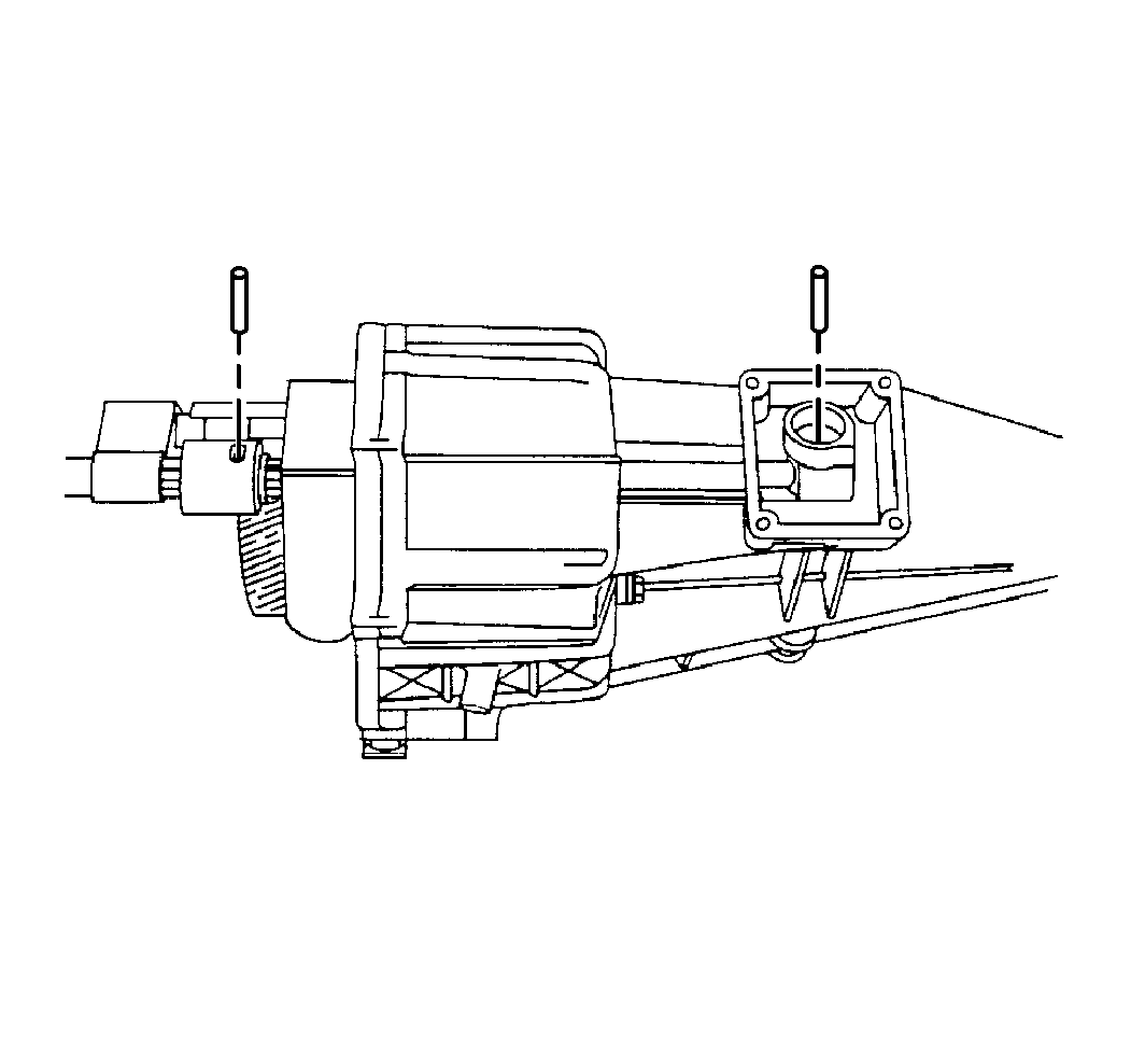
| • | Rotate the shift shaft lever and the shift shaft bushing. |
| Important: Do not lose the shift shaft lever plunger or the spring when removing the shift shaft lever roll pin from the rear housing. |
| • | Remove the shift shaft lever plunger and the spring. |
| • | Support the shift shaft end while driving out the shift shaft lever roll pin. |
| • | Allow the roll pin to clear the second gear during removal. |
Notice: Do not use excessive force when removing the shift shaft. Excessive force will "peen" the shift shaft and damage the rear housing shift shaft bearing causing increased shift effort.
Important:
• Do not bend the shift rail when removing the roll pin. • Use an air gun with a 5 mm (3/16 inch) drift punch
in order to remove the roll pin. • The roll pin will fall into the rear housing.
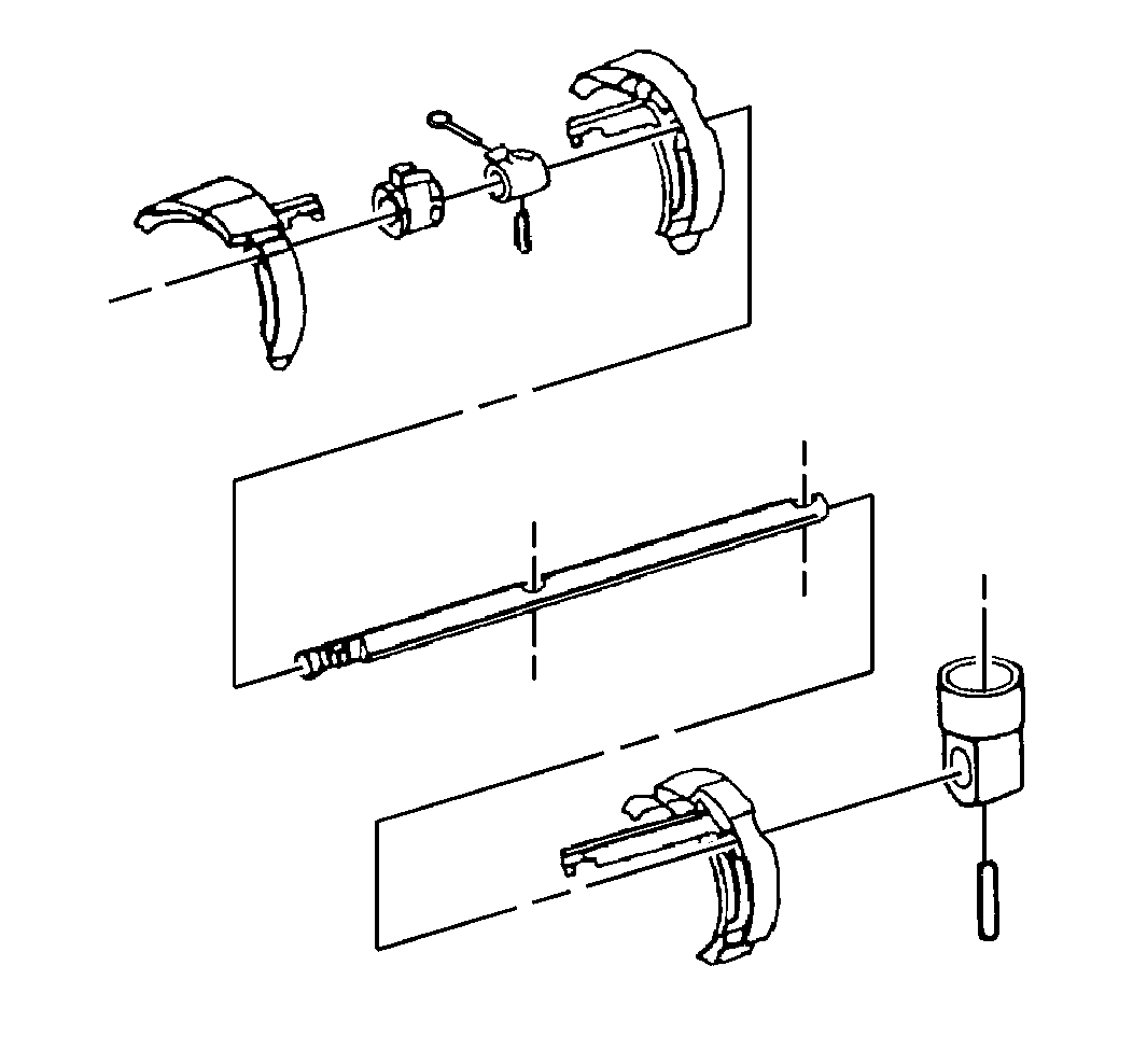
Notice: Do not use excessive force when removing the shift shaft. Excessive force will "peen" the shift shaft and damage the rear housing shift shaft bearing causing increased shift effort.
| • | The shift shaft |
| • | The shift shaft socket |
| • | The lever |
| • | The shift shaft block-out bushing |
Remove the third-fourth shift fork.
The countershaft bearing must be pressed off the counter shaft.
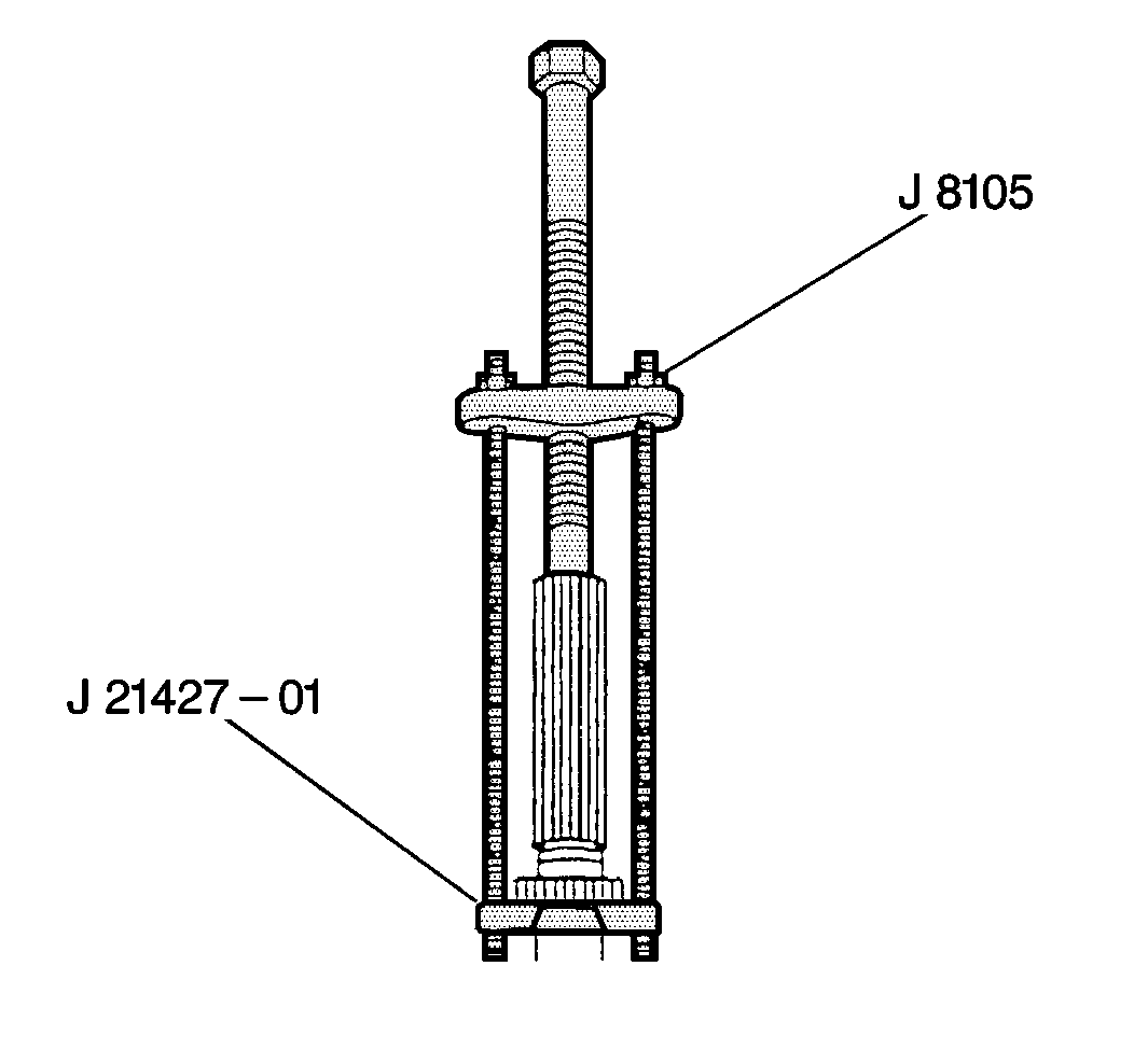
Discard the speed sensor rotor.
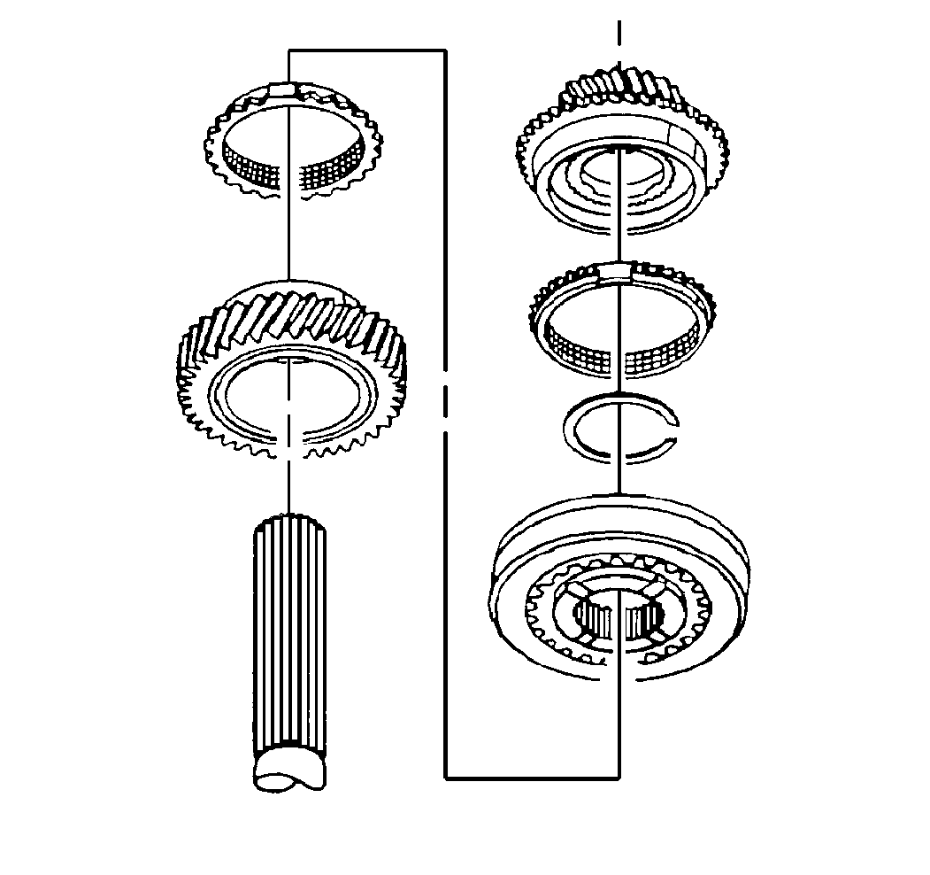
| • | The synchronizer blocking ring |
| • | The synchronizer and the hub |
| • | The synchronizer blocking ring |
| • | The reverse speed gear assembly |
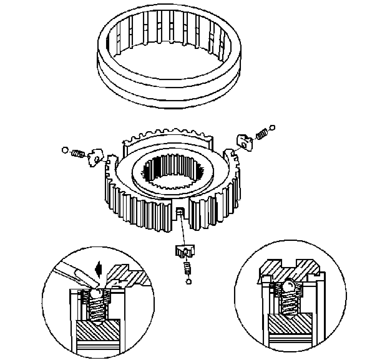
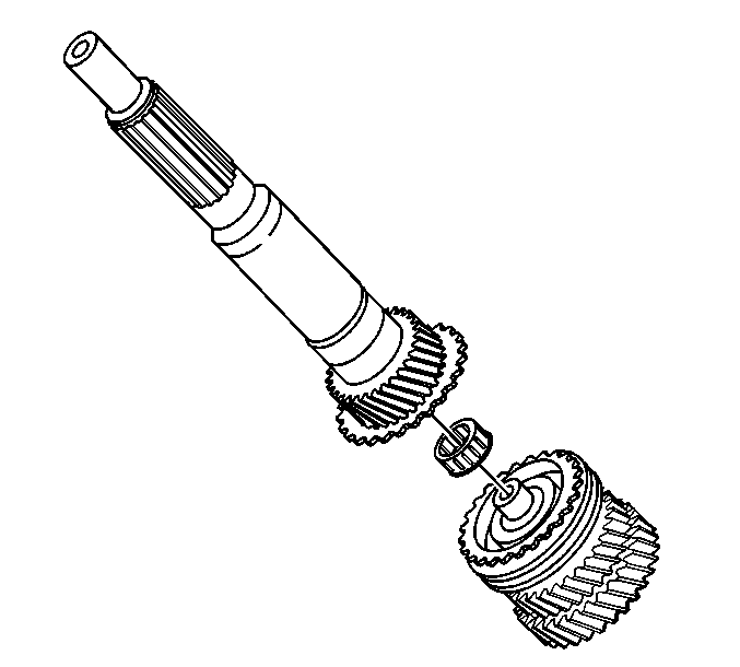
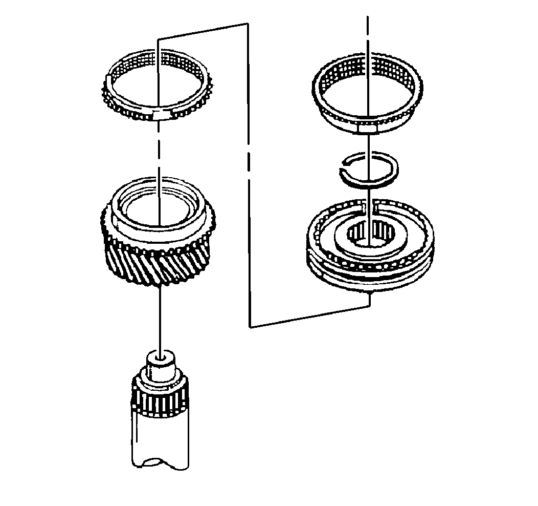
| • | The third-fourth synchronizer assembly |
| • | The synchronizer blocking rings |
| • | The third speed gear |
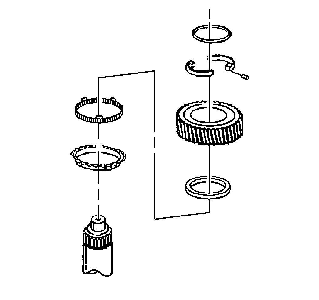
| • | The retaining ring |
| • | The pin |
| • | The two thrust washer halves |

| • | The inner cone |
| • | The middle cone |
| • | The synchronizer ring |
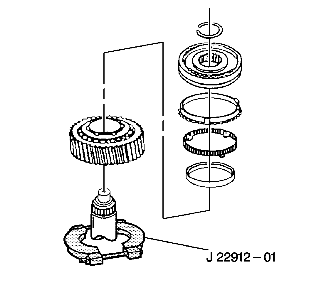
Important: Scribe the synchronizer hub to the output shaft prior to disassembly.
| • | The synchronizer |
| • | The synchronizer ring |
| • | The inner cone |
| • | The middle cone |
| • | The first gear |

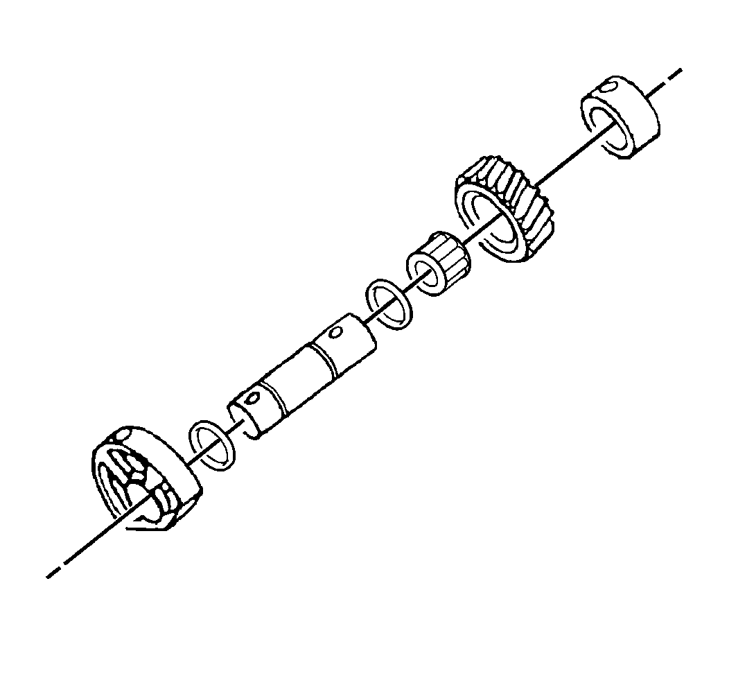
| • | The segment |
| • | The gear |
| • | The bearing assembly |
| • | The collar |
| • | The two O-rings from the shaft |
Tools Required
| • | J 8105 Gear Puller |
| • | J 21427-A Speedometer Gear Puller Adapter |
| • | J 22912-01 Separator Plate |
| • | J 23907 Slide Hammer and Adaptor |
| • | J 36509 Detent Spring Plug Remover |
- Remove the two bolts which attach the idler shaft segment and the idler shaft support collar to the rear housing.
- Remove the backup lamp switch from the rear housing.
- Remove the bolt and the electronic speed sensor from the rear housing.
- Remove the shift shaft block-out bushing pin from the front housing.
- Use the J 36509 and the J 23907 in order to remove the following components from the front housing:
- Slide the hammer with the 6 mm end into the hole in the front housing.
- Remove the five bolts which secure the input shaft bearing retainer to the front housing.
- Use the J 23907 to remove the input shaft bearing retainer from the front housing.
- Remove the snap ring.
- Remove the nine bolts which attach the front housing to the rear housing.
- Angle the front housing up and press down on the rear housing in order to separate the front housing from the rear housing.
- Remove the countershaft roller bearing from the countershaft or the bearing shell.
- Remove the shift shaft lever roll pin from the shift shaft lever:
- Remove the shift shaft socket roll pin from the bottom of the shift shaft socket.
- Remove the following components:
- Rotate the third-fourth shift fork counterclockwise.
- Remove the five bolts which secure the output shaft bearing retainer to the center of the rear housing.
- Remove the rear housing from the gear assemblies.
- Remove the reverse idler gear assembly.
- Remove the output shaft bearing retainer.
- Remove the shift forks.
- Remove the countershaft.
- Remove the countershaft bearing snap ring.
- Remove the countershaft bearing.
- Remove the fifth counter gear from the counter shaft.
- Use the J 21427-A and the J 8105 to remove the speed sensor rotor from the output shaft.
- Remove the snap ring from the output shaft.
- Use the J 21427-A and the J 8105 to remove the output shaft bearing from the output shaft.
- Remove the fifth speed gear from the output shaft.
- Remove the snap ring from the output shaft.
- Remove the following components from the output shaft:
- Leave the synchronizer rings on the fifth-reverse synchronizer assembly in order to prevent the synchronizer detent balls from popping out.
- Remove the input shaft and the pocket bearing from the output shaft.
- Remove the snap ring.
- Use a hydraulic press in order to remove the following components from the main shaft:
- Remove the following components from the main shaft:
- Remove the second gear from the main shaft.
- Remove the following components from the main shaft:
- Remove the snap ring.
- Use the J 22912-01 and a hydraulic press to remove the following components:
- Leave the synchronizer rings on the first-second synchronizer assembly in order to prevent the synchronizer detent balls from popping out.
- Remove the following components from the reverse idler shaft:


| • | The detent plug |
| • | The spring |
| • | The plunger |


| • | Rotate the shift shaft lever and the shift shaft bushing. |
| Important: Do not lose the shift shaft lever plunger or the spring when removing the shift shaft lever roll pin from the rear housing. |
| • | Remove the shift shaft lever plunger and the spring. |
| • | Support the shift shaft end while driving out the shift shaft lever roll pin. |
| • | Allow the roll pin to clear the second gear during removal. |
Important:
• Do not bend the shift rail when removing the roll pin. • Use an air gun with a 5 mm (3/16 inch) drift punch
in order to remove the roll pin. • The roll pin will fall into the rear housing.

| • | The shift shaft |
| • | The shift shaft socket |
| • | The lever |
| • | The shift shaft block-out bushing |
Remove the third-fourth shift fork.

The countershaft bearing must be pressed off the counter shaft.

Discard the speed sensor rotor.

| • | The synchronizer blocking ring |
| • | The synchronizer and the hub |
| • | The synchronizer blocking ring |
| • | The reverse speed gear assembly |


| • | The third-fourth synchronizer assembly |
| • | The synchronizer blocking rings |
| • | The third speed gear |

| • | The retaining ring |
| • | The pin |
| • | The two thrust washer halves |

| • | The inner cone |
| • | The middle cone |
| • | The synchronizer ring |

Important: Scribe the synchronizer hub to the output shaft prior to disassembly.
| • | The synchronizer |
| • | The synchronizer ring |
| • | The inner cone |
| • | The middle cone |
| • | The first gear |


| • | The segment |
| • | The gear |
| • | The bearing assembly |
| • | The collar |
| • | The two O-rings from the shaft |
