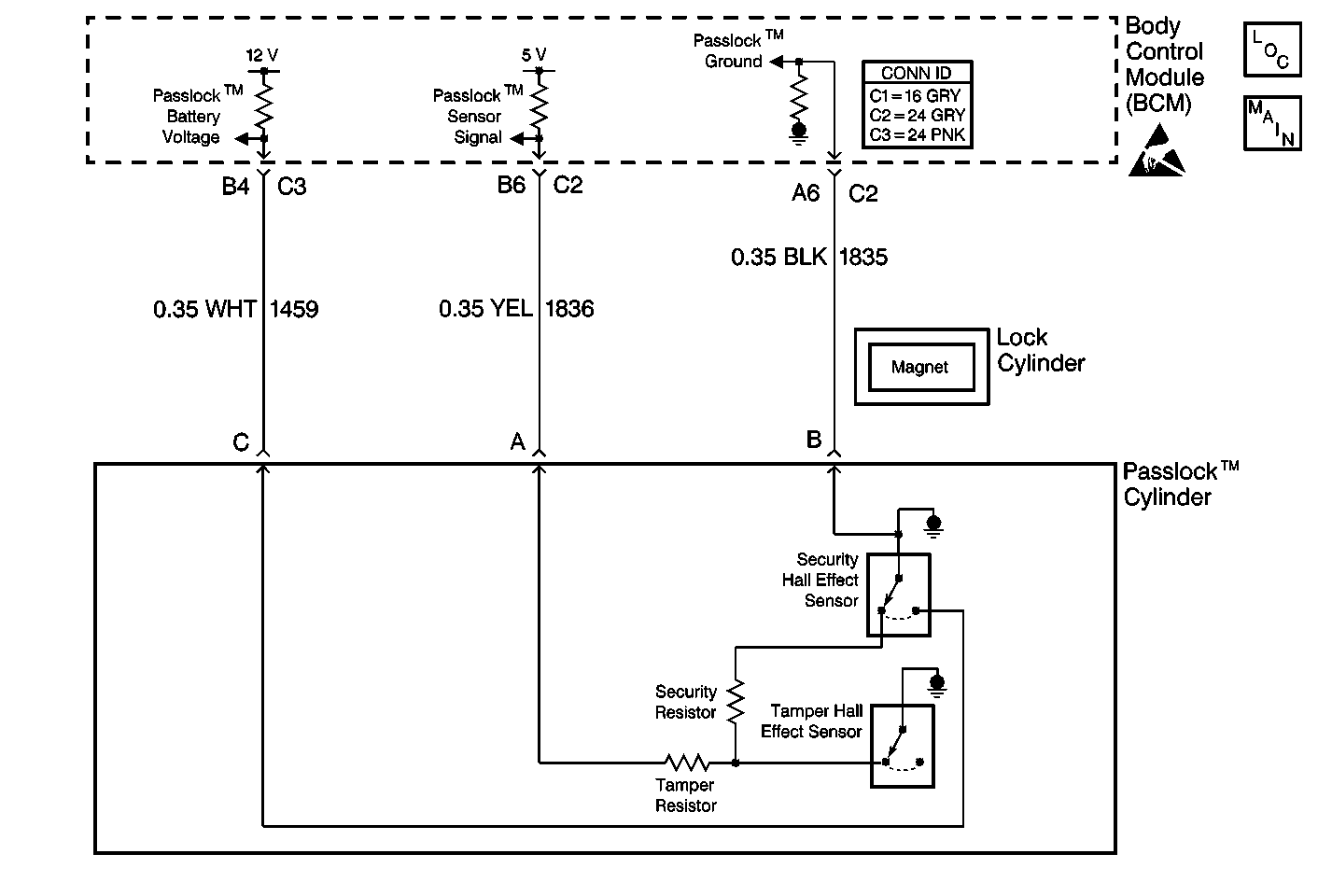
Circuit Description
The security system power circuit supplies power from the body control module (BCM) to the Passlock™ sensor on CKT 1459.
Conditions for Setting the DTC
All of the following conditions must be met:
| • | The Passlock™ power is active. |
| • | The Passlock™ power feedback is not present for 1 second. |
Action Taken When the DTC Sets
| • | The BCM turns OFF the Passlock™ power as long as a current fault code is set. |
| • | The BCM stores DTC B2947 in the BCM memory. |
| • | The vehicle will start immediately and then stall. |
| • | The security indicator remains illuminated. |
Conditions for Clearing the DTC
| • | The BCM goes to sleep and reinitializes with the fault cleared. |
| • | All of the BCM history codes are cleared after 100 ignition cycles (from OFF to ON) with no current codes active during the 100 ignition cycles. |
| • | Use a scan tool. |
Diagnostic Aids
| • | Inspect for a bad connection at the Passlock® Sensor and the BCM. |
| • | If the DTC is a history DTC, the problem may be intermittent. Perform the tests shown while wiggling the wiring and connectors. This action often causes the malfunction to appear. |
Test Description
The numbers below refer to the numbers on the diagnostic table.
Step | Action | Value(s) | Yes | No |
|---|---|---|---|---|
|
Important: A short to ground will cause an open fuse(s). Before performing this diagnostic procedure, inspect the fuse(s) for an open. | ||||
1 | Was the Theft Deterrent Systems diagnostic system check performed? | -- | Go to Step 2 | |
Is the measured resistance equal to the specified value? | OL | Go to Step 4 | Go to Step 3 | |
3 | Repair the short to ground in CKT 1459 between the Passlock® connector terminal C and the BCM connector C3 terminal B4. Refer to Wiring Repairs in Wiring Systems Is the repair complete? | -- | Go to Step 11 | -- |
4 | Inspect for a poor connection at the BCM connector C3 terminal B4, CKT 1459. Was a poor connection found? | -- | Go to Step 5 | Go to Step 6 |
5 | Repair the poor connection at the BCM connector C3 terminal B4. Refer to Wiring Repairs in Wiring Systems Is the repair complete? | -- | Go to Step 11 | -- |
6 | Inspect for a poor connection at the Passlock® sensor terminal C. Was a poor connection found? | -- | Go to Step 7 | Go to Step 8 |
7 | Repair the poor connection at the Passlock® sensor terminal C. Refer to Wiring Repairs in Wiring Systems Is the repair complete? | -- | Go to Step 11 | -- |
8 |
Does the Passlock Power data parameter display the value shown? | ACTIVE | Go to Step 9 | Go to Step 10 |
9 |
Is the repair complete? | -- | Go to Step 11 | -- |
10 |
Is the repair complete? | -- | Go to Step 11 | -- |
11 | Clear the DTCs from the memory. Is the repair complete? | -- | -- | |
