Reduced Operating Range of Remote Keyless Entry (RKE) System With Blower Motor Running at High Speed (Diagnose and Install External RKE Receiver, If Necessary)

| Subject: | Reduced Operating Range of Remote Keyless Entry (RKE) System With Blower Motor Running At High Speed (Diagnose and Install External RKE Receiver, If Necessary) |
| Models: | 2001 Oldsmobile Alero |
| 2001 Pontiac Grand Am |
Condition
Some customers may comment that the Remote Keyless Entry (RKE) System will not work at times or has an extremely poor range.
Cause
This condition may be encountered on vehicles produced prior to November of 2000, with the non-remote mounted RKE module system. This will become a concern for those customers who start the vehicle to allow it to cool or warm and let it sit in the driveway with the doors locked. They then try to enter the vehicle using the key fob and find they are unable to unlock the doors. The limited range is the result of electromagnetic interference (EMI) from the blower motor. The faster the blower is running, the more limited the working range of the RKE system key fob becomes.
Diagnosis
An aid to the diagnosis of this concern would be the following:
| • | The customer's key fob is easily separated from the vehicle's key. |
| • | The vehicle has a remote starter system installed. |
- Connect the Tech 2 to the vehicle ALDL connector.
- Power up the Tech 2 and enter the main menu.
- From the main menu, select Diagnostics.
- Select 2001 for the model year.
- With passenger car highlighted, press enter.
- Select F1, Body.
- Select the car line, N, and press enter.
- Select the marketing division for the vehicle being serviced.
- Select F0, Body Control Module.
- Select F4, ID Information.
- Select F0, Module Information.
- Select F1, Option Configuration.
- Record, for future reference, the status of all options displayed. This information will be needed later.
Important: If the Tech 2 displays the RFA location as EXTERNAL, the vehicle is already configured to the external module and you should exit this procedure as the vehicle does not need upgrading. Refer to the published Service Information for diagnosis of the customer concern.
Correction
The correction will be to install an external RKE receiver and associated wiring as required in the vehicle. The different repair procedures are listed here.
| • | Oldsmobile Alero 4-door vehicles without Monsoon audio system, use repair procedure #1 |
| • | Oldsmobile Alero 4-door vehicles with Monsoon audio system, use repair procedure #2 |
| • | Oldsmobile Alero 2-door vehicles without Monsoon audio system, use repair procedure #3 |
| • | Oldsmobile Alero 2-door vehicles with Monsoon audio system, use repair procedure #4 |
| • | Pontiac Grand Am 4-door vehicles, use repair procedure #2 |
| • | Pontiac Grand Am 2-door vehicles, use repair procedure #4 |
Repair Procedure #1 -- Oldsmobile Alero 4-door vehicles without Monsoon audio system only
- Open the hood, install fender covers and disconnect the negative battery cable.
- Install seat covers.
- Remove the fuse panel door from the left end of the instrument panel.
- Remove the left side sound insulator panel.
- Remove the front and rear door opening carpet retainers.
- Remove the rear seat cushion from the vehicle, using a flat-bladed tool to release the retainers.
- Remove the bolts retaining the rear seat back/side bolsters (one (1) on each side of the vehicle).
- On vehicles with fold down rear seat backrests, open the rear deck lid (trunk) and pull the release strap to allow fold down of the rear seat backrest cushions.
- For those vehicles without fold down rear seat backrests, remove the rear seat back rest.
- Remove the left side lower B pillar trim.
- Remove the left side C pillar molding.
- Using the J 38788 tool, remove the push-in retainers (2) which retain the rear shelf trim panel to the seat backrest support.
- Remove the rear shelf trim panel.
- Remove the trim panel end supports/pad from the left side of the vehicle.
- Install the remote control receiver module to the center of the rear panel in the space provided.
- Connect the new wiring harness connector to the remote control receiver module.
- Locate ground splice pack (G401). It is a black connector about 38 mm (1.5 in) square next to the left rear speaker. Remove the retaining screw and the CPA from the connector.
- Route the black wire of the new harness to left side ground splice pack. Insert the terminal for the black wire into any empty cavity. Re-install the CPA and retaining screw.
- Route the orange and purple wires along the existing wiring harness and into the convoluted tubing for the wiring harness down the left side of the vehicle passenger compartment and to the left I/P fuse block.
- Loosen the bolt retaining connector 3 (C3) (#1 in the illustration) to the face of the left I/P fuse block and release the retaining tabs. The retaining tabs are adjacent to the retaining screw on each side of the connector. Insert the blue pick, #GM12094430 7J04898, from the Electrical Tool Kit to depress the small retaining tabs which will allow the connector to be disconnected from the fuse block.
- From the front side of the C3 connector, insert an ice pick type tool along side the bolt threads and snap the small metal collar around the screw to allow removal of the connector retaining screw and clear plastic cover from the C3 connector.
- Place the terminal of the orange wire of the new harness into cavity B5 of C3.
- Place the terminal of the purple wire of the new harness into cavity A5 of C3.
- Re-connect C3 to the fuse panel and install the clear plastic cover.
- Re-install the fuse panel cover to the left I/P.
- Remove the right insulator panel.
- Remove the body control module (BCM).
- Install a new BCM.
- Re-install the right insulator panel.
- Re-install the trim panel supports and trim panel to the rear shelf.
- Re-install the trim panel push pin retainers.
- Re-install the "B" and "C" pillar trim.
- Re-install the rear seat side bolsters/back rest assembly.
- Re-install the seatback/side bolster retainers.
- Re-install the rear seat cushion into the vehicle and properly secure it into place.
- Re-install the carpet retainers in the front and rear door areas.
- Re-install the left side sound insulator panel.
- Proceed to Vehicle Configuration, found later in this bulletin.
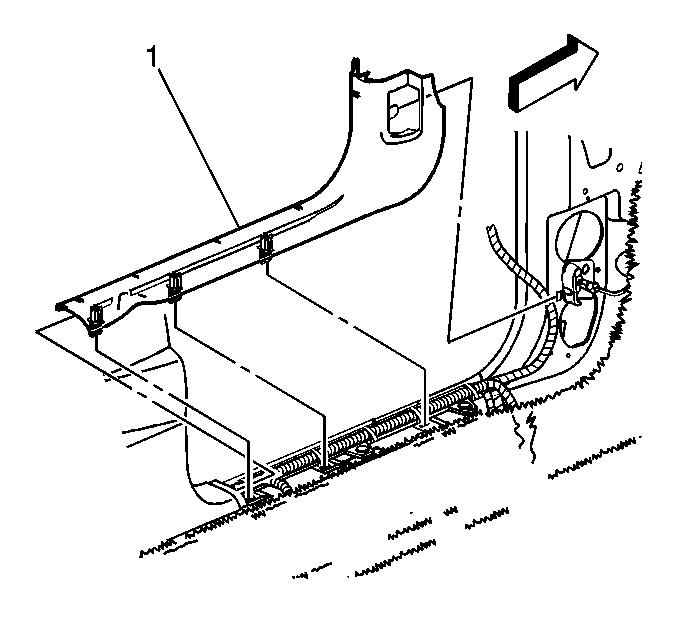
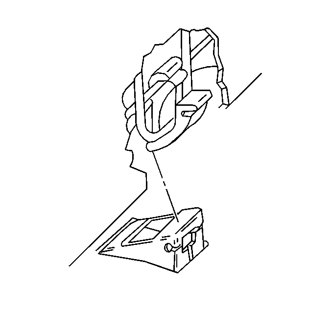
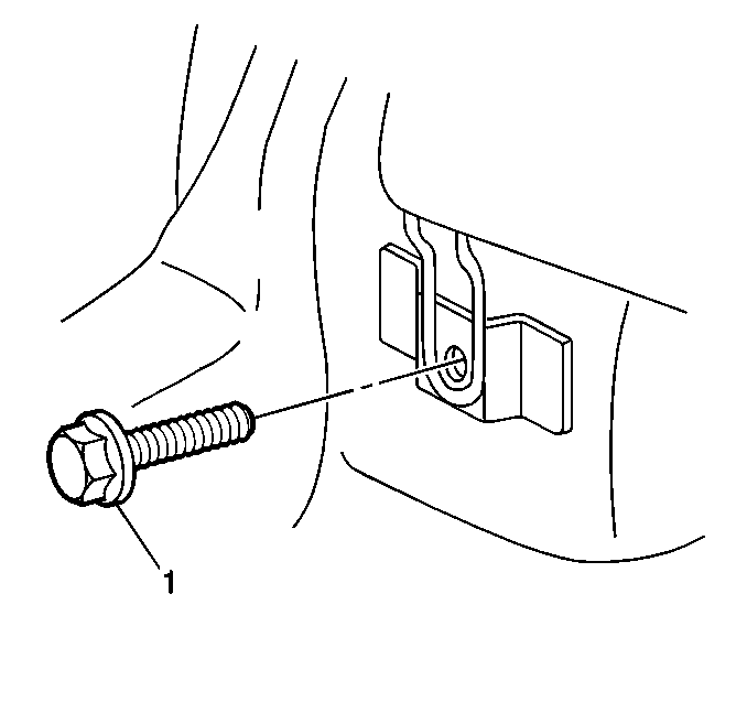
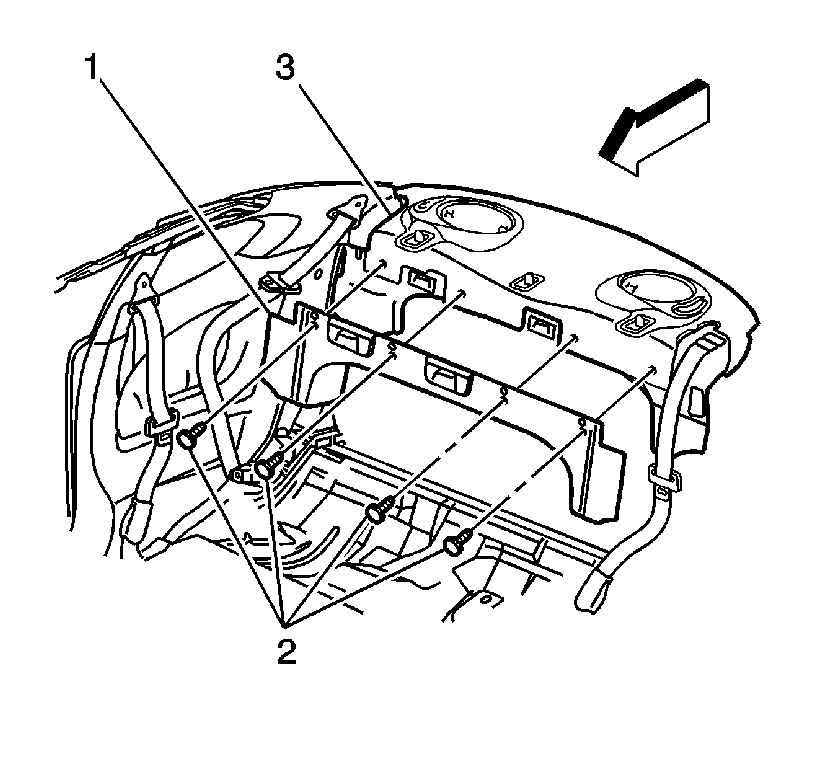
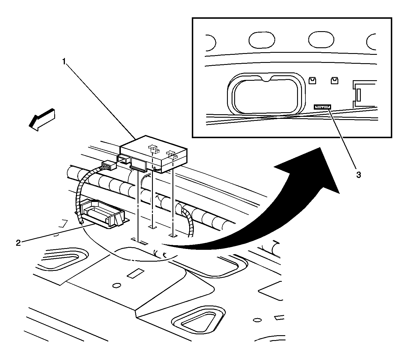
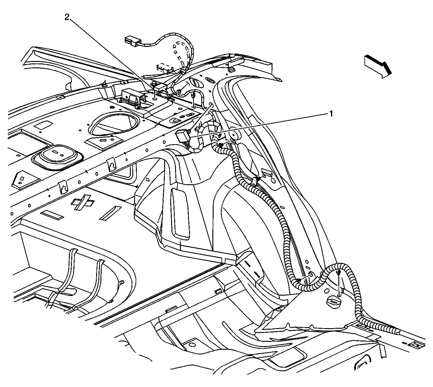
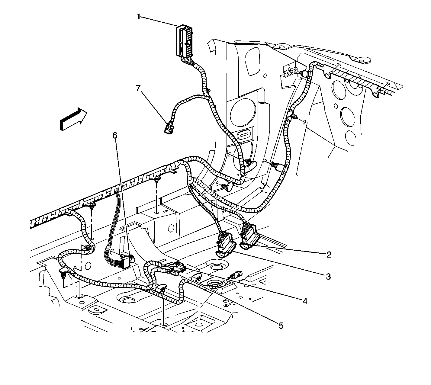
Tighten
Tighten the retaining screw to 6 N·m(53 lb in).
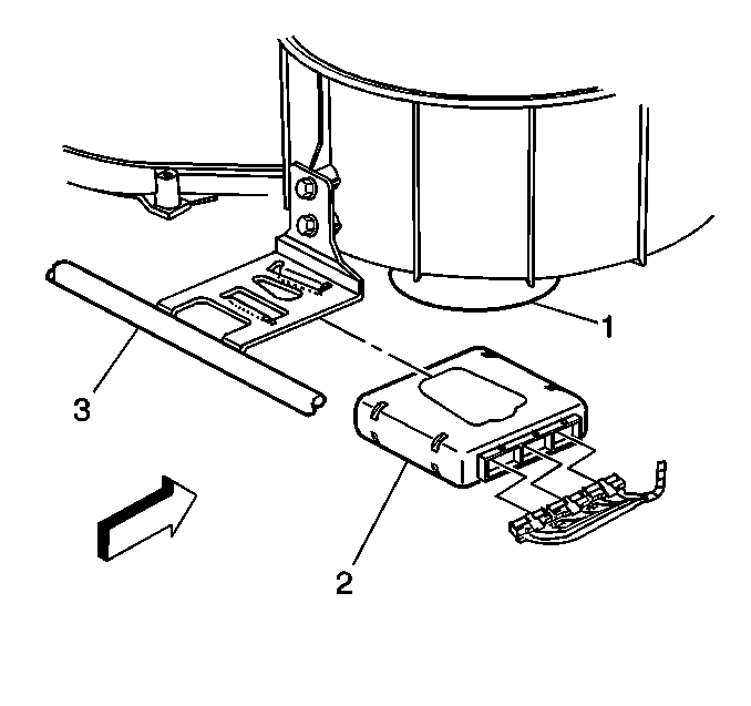
Tighten
Tighten the retainers to 12 N·m(106 lb in).
Repair Procedure #2 -- Oldsmobile Alero 4-door vehicles with Monsoon audio system and all Pontiac Grand Am 4-door vehicles
- Open the hood, install fender covers and disconnect the negative battery cable.
- Install seat covers.
- Remove the rear seat cushion from the vehicle using a flat-bladed tool to release the retainers.
- Remove the bolts retaining the rear seat back/side bolsters (if equipped) (one (1) on each side of the vehicle).
- On vehicles with fold down rear seat backrests, open the rear deck lid (trunk) and pull the release strap to allow fold down of the rear seat backrest cushions.
- For those vehicles without fold down rear seat backrests, remove the rear seat back rest.
- Using the J 38788 tool, remove the push-in retainers (2) which retain the rear shelf trim panel to the seat backrest support.
- Remove the rear shelf trim panel.
- Remove the trim panel end supports/pad from the left side of the vehicle.
- Install the remote control receiver module to the center of the rear panel in the space provided.
- Connect the wiring harness connector to the remote control receiver module. The wiring harness should be laying on top of the rear shelf panel.
- Remove the right insulator panel.
- Remove the body control module (BCM).
- Install a new BCM.
- Re-install the right insulator panel.
- Re-install the trim panel supports and trim panel to the rear shelf.
- Re-install the trim panel push pin retainers.
- Re-install the rear seat side bolsters/back rest assembly, if equipped.
- Re-install the seatback/side bolster retainers.
- Re-install the rear seat cushion into the vehicle and properly secure it into place.
- Proceed to Vehicle Configuration, found later in this bulletin.


Tighten
Tighten the retainers to 12 N·m(106 lb in).
Repair Procedure #3 -- Oldsmobile Alero 2-door vehicles without Monsoon audio system only
- Open the hood, install fender covers and disconnect the negative battery cable.
- Install seat covers.
- Remove the fuse panel door from the left end of the instrument panel.
- Remove the left side sound insulator panel.
- Remove the left door opening carpet retainer.
- Remove the rear seat cushion from the vehicle using a flat-bladed tool to release the retainers.
- On vehicles with fold down rear seat backrests, open the rear deck lid (trunk) and pull the release strap to allow fold down of the rear seat backrest cushions.
- Remove the rear seat back rest.
- Remove the bolts retaining the rear seat back/side bolsters (if equipped) (one (1) on each side of the vehicle).
- Remove the right door opening carpet retainer.
- Remove both rear quarter lower trim panels.
- Remove the covers and bolts from the rear upper seat belt anchors.
- Remove the garment hooks from both sides of the vehicle.
- Remove both rear quarter upper trim panels.
- Using the J 38788 tool, remove the push-in retainers (2) which retain the rear shelf trim panel to the seat backrest support.
- Remove the rear shelf trim panel.
- Remove the trim panel end supports/pad from the left side of the vehicle.
- Install the remote control receiver module to the center of the rear panel in the space provided.
- Connect the new wiring harness connector to the remote control receiver module.
- Locate ground splice pack (G401). It is a black connector about 38 mm (1.5 in) square next to the left rear speaker. Remove the retaining screw and CPA from the connector.
- Route the black wire of the new harness to left side ground splice pack. Insert the terminal for the black wire into any empty cavity. Re-install the CPA and retaining screw.
- Route the orange and purple wires along the existing wiring harness and into the convoluted tubing for the wiring harness down the left side of the vehicle passenger compartment and to the left I/P fuse block.
- Loosen the bolt retaining connector 3 (C3) (#1 in the illustration) to the face of the left I/P fuse block and release the retaining tabs. The retaining tabs are adjacent to the retaining screw on each side of the connector. Insert the blue pick, #GM12094430 7J04898, from the Electrical Tool Kit to depress the small retaining tabs which will allow the connector to be disconnected from the fuse block.
- From the front side of the C3 connector, insert an ice pick type tool along side the bolt threads and snap the small metal collar around the screw to allow removal of the connector retaining screw and clear plastic cover from the C3 connector.
- Place the terminal of the orange wire of the new harness into cavity B5 of C3.
- Place the terminal of the purple wire of the new harness into cavity A5 of C3.
- Re-connect C3 to the fuse panel and install the clear plastic cover.
- Re-install the fuse panel cover to the left I/P.
- Remove the right insulator panel.
- Remove the body control module (BCM).
- Install a new BCM.
- Re-install the right insulator panel.
- Re-install the trim panel supports and trim panel to the rear shelf.
- Re-install the trim panel push pin retainers.
- Re-install the rear quarter upper trim panels.
- Re-install the garment hooks.
- Properly position the rear seat shoulder harness retractor and install the bolt.
- Re-install both lower rear quarter trim panels.
- Re-install the rear seat side bolsters/back rest assembly.
- Re-install the seatback/side bolster retainers.
- Re-install the rear seat cushion into the vehicle and properly secure it into place.
- Re-install the carpet retainers in both front door areas.
- Re-install the left side sound insulator panel.
- Proceed to Vehicle Configuration, found later in this bulletin.


Tighten
Tighten the retaining screw to 6 N·m(53 lb in).

Tighten
Tighten the bolt to 36 N·m(27 lb ft).
Tighten
Tighten the retainers to 12 N·m(106 lb in).
Repair Procedure #4 -- Oldsmobile Alero 2-door vehicles with Monsoon audio system and all Pontiac Grand Am 2-door vehicles
- Open the hood, install fender covers and disconnect the negative battery cable.
- Install seat covers.
- Remove the left door opening carpet retainer.
- Remove the rear seat cushion from the vehicle using a flat-bladed tool to release the retainers.
- On vehicles with fold down rear seat backrests, open the rear deck lid (trunk) and pull the release strap to allow fold down of the rear seat backrest cushions.
- Remove the rear seat back rest.
- Remove the bolts retaining the rear seat back/side bolsters (if equipped) (one (1) on each side of the vehicle).
- Remove the right door opening carpet retainer.
- Remove both rear quarter lower trim panels.
- Remove the covers and bolts from the rear upper seat belt anchors.
- Remove the garment hooks from both sides of the vehicle.
- Remove both rear quarter upper trim panels.
- Using the J 38788 tool, remove the push-in retainers (2) which retain the rear shelf trim panel to the seat backrest support.
- Remove the rear shelf trim panel.
- Remove the trim panel end supports/pad from the left side of the vehicle.
- Install the remote control receiver module to the center of the rear panel in the space provided.
- Connect the wiring harness connector to the remote control receiver module. The wiring harness should be laying on top of the rear shelf panel.
- Remove the right insulator panel.
- Remove the body control module (BCM).
- Install a new BCM.
- Re-install the right insulator panel.
- Re-install the trim panel supports and trim panel to the rear shelf.
- Re-install the trim panel push pin retainers.
- Re-install the rear quarter upper trim panels.
- Re-install the garment hooks.
- Properly position the rear seat shoulder harness retractor and install the bolt.
- Re-install both lower rear quarter trim panels.
- Re-install the rear seat side bolsters/back rest assembly.
- Re-install the seatback/side bolster retainers.
- Re-install the rear seat cushion into the vehicle and properly secure it into place.
- Re-install the carpet retainers in both front door areas.
- Proceed to Vehicle Configuration, found later in this bulletin.


Tighten
Tighten the bolt to 36 N·m(27 lb ft).
Tighten
Tighten the retainers to 12 N·m(106 lb in).
Vehicle Configuration:
The following steps must be performed to configure the vehicle and allow the theft deterrent system to recognize the vehicle.
- Re-connect the negative battery cable.
- Re-connect the Tech 2 to the ALDL connector.
- Turn the key to the RUN position, engine OFF.
- Select Remote Function Actuation.
- Select Special Functions.
- Select Program Key Fobs.
- Select the number of key fobs to be programmed.
- Press and hold the LOCK and UNLOCK buttons simultaneously on the first transmitter for approximately 15 seconds. The power locks should cycle to confirm programing of the first transmitter is complete.
- Repeat the previous step for all other transmitters issued with the vehicle.
- Exit out to the main screen of the Tech 2.
- Turn the key to the Off position. Disconnect the Tech 2 and wait 30 seconds.
- Re-connect the Tech 2 to the ALDL.
- Turn the key to the ON position.
- Power on the scan tool and enter the main menu.
- From the main menu, select Diagnostics.
- Select 2001 for the model year.
- With correct passenger car highlighted, press enter.
- Select F1, Body.
- Select the car line, N, and press enter.
- Select the marketing division for the vehicle being serviced.
- Select F0, Body Control Module.
- Select F2, Special.
- Select F2, New BCM setup.
- When asked "Do you want to Setup a new BCM?", press the softkey under Yes.
- Exit back to the main menu.
- Select SPS programming and follow the on-screen instructions.
- After SPS programming has been completed, turn the key to the OFF position for 30 seconds.
- Perform the 30 Minute Learn Procedure from Programming Theft Deterrent System Components. Refer to the Programming Theft Deterrent System Components in the Theft Deterrent sub-section of the printed Service Manual (page 8-574) or Document ID #651700 in SI2000.
Tighten
Tighten the cable retainer to 15 N·m(11 lb ft).
Parts Information
Part Number | Description | Qty |
|---|---|---|
25695953 | RFA Module, Keyless Entry | 1 |
12206799 | Body Control Module | 1 |
22684145* | Harness, Remote Wiring | 1 |
25695954 | Transmitter Fob - External receiver Transmitter #1 | 1 |
25695955 | Transmitter Fob - External receiver Transmitter #2 | 1 |
*The wiring harness is only required in Oldsmobile Alero vehicles without the Monsoon audio system. | ||
Parts are currently available from GMSPO.
Warranty Information
For vehicles repaired under warranty, use:
Labor Operation | Procedure Number | Vehicle Description | Labor Operation Description | Labor Time | |
|---|---|---|---|---|---|
R4804 | 1 | Oldsmobile Alero 4-door vehicles (w/o Monsoon audio system) | Convert Vehicle from Internal to External RKE | 2.1 hrs | |
2 | Oldsmobile Alero 4-door vehicles (w/Monsoon audio system) and all Pontiac Grand Am 4-door vehicles | 1.8 hrs | |||
3 | Oldsmobile Alero 2-door vehicles (w/o Monsoon audio system) | 2.3 hrs | |||
4 | Oldsmobile 2-door vehicles (w/Monsoon audio system) and all Pontiac Grand AM 2-door vehicles | 1.9 hrs | |||
