Circuit Description
This code (both current and history) indicates that the body control module (BCM) has sensed a short to voltage condition on the instrument cluster serial peripheral interface (SPI) data line to the BCM.
Conditions for Setting the DTC
All of the following conditions:
| • | Ignition 0 is active. |
| • | The serial data line from the IPC to the BCM is open or shorted to voltage for 5 seconds. |
Action Taken When the DTC Sets
Stores DTC U2003 in the BCM memory
Conditions for Clearing the DTC
| • | The BCM goes to sleep and reinitializes with the malfunction cleared. |
| • | All the BCM history codes will be cleared after 100 ignition cycles (from OFF to ON) with no current codes active during the 100 ignition cycles. |
| • | Use the scan tool. |
Diagnostic Aids
| • | With the ignition switch in the ON position, test for voltage transitions on the SPI data line. |
| • | When the diagnostics direct you to take electrical measurements at the wiring harness junction blocks, refer to Power and Grounding Component Views . |
| • | If the DTC is a history DTC, the problem may be intermittent. Perform the above tests while wiggling the wiring and connectors. This may often cause the malfunction to appear. |
Test Description
The numbers below refer to the numbers on the diagnostic table.
-
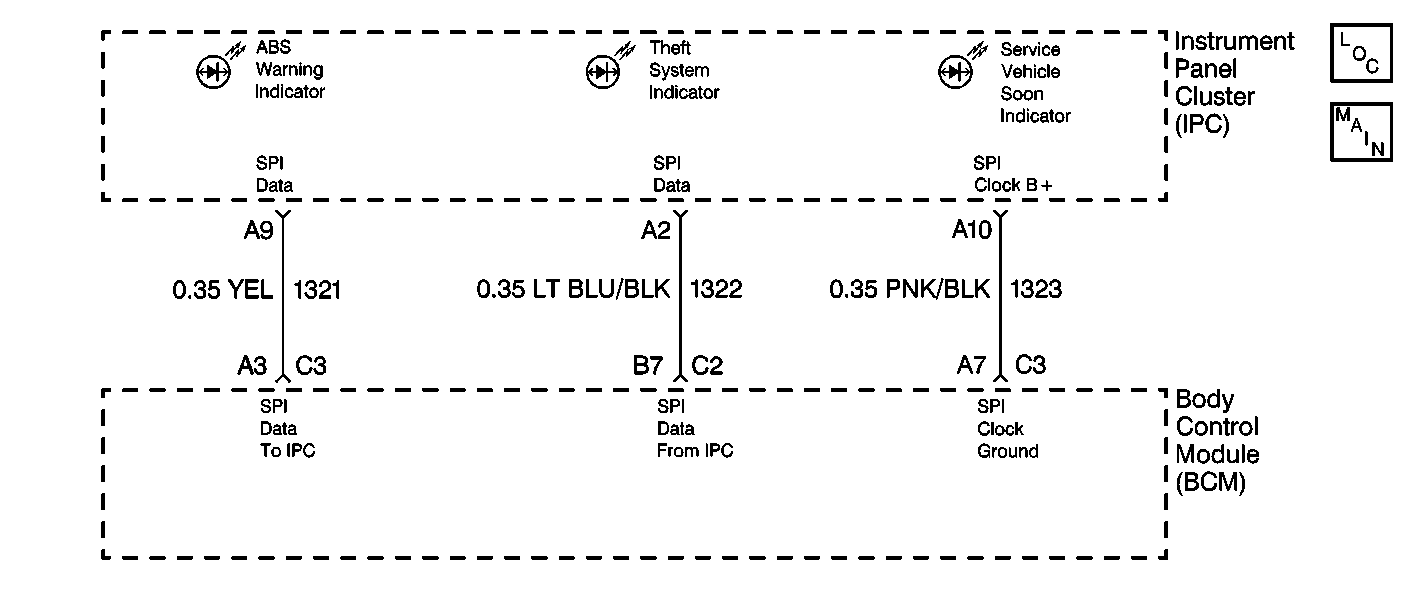
This step determines if there is a short to the battery in CKT 1322 between the body control module (BCM) and the instrument cluster.
-
This step determines if there is a bad connection at the instrument cluster or the BCM.
Step | Action | Value(s) | Yes | No |
|---|---|---|---|---|
1 | Was the body control module (BCM) diagnostic system check performed? | -- | Go to Step 2 | |
Disconnect the BCM connector C2 terminal B7 CKT 1322. Use the J 39200 in order to measure the voltage in CKT 1322 between the BCM harness connector C2 terminal B7 and ground. Does the measured voltage equal the specified value? | Greater than 0 V | Go to Step 3 | Go to Step 4 | |
3 | Repair the short to voltage in the CKT 1322 between the BCM connector C2 terminal B7 and the instrument cluster connector A2. Refer to Wiring Repairs . Is the CKT repair complete? | -- | Go to Step 11 | -- |
Is the SPI data input LOW? | -- | Go to Step 8 | Go to Step 5 | |
5 | Inspect for a poor connection at the connector C2 terminal B7 CKT 1322. Is a poor connection found? | -- | Go to Step 6 | Go to Step 7 |
6 | Repair the poor connection in CKT 1322. Refer to Wiring Repairs . Is the CKT repair complete? | -- | Go to Step 11 | -- |
7 | Replace the BCM. Refer to the following procedures: Is the repair complete? | -- | Go to Step 11 | -- |
8 | Inspect for a poor connection at the instrument cluster connector terminal A2 CKT 1322. Is a poor connection found? | -- | Go to Step 9 | Go to Step 10 |
9 | Repair the poor connection at the instrument cluster connector terminal A2. Refer to Wiring Repairs . Is the CKT repair complete? | -- | Go to Step 11 | -- |
10 | Replace the instrument cluster. Refer to Instrument Cluster Replacement in Instrument Panel, Gauges and Console. Is the repair complete? | -- | Go to Step 11 | -- |
11 | Clear the DTCs from the memory. Are the DTCs cleared from the memory? | -- | -- |
