AXLE SHAFT END PLAY CHECKING PROCEDURE

MODELS/YEARS 1978-80 CUTLASS "A" MODELS
CONDITION
This notice is sent to you pursuant to an agreement of settlement between the Department of Transportation and General Motors Corporation.
In April 1983, the National Highway Traffic Safety Administration (NHTSA) made an initial determination that a defect which relates to motor vehicle safety exists in certain 1978-80 Oldsmobile Cutlass vehicles. Specifically, the NHTSA determined, at that time, that some of these vehicles "may be manufactured with rear axle shafts with thin end buttons" and that "this condition may result in disengagement or separation of the axle shaft and wheel assembly from the vehicle, which could lead to loss of vehicle control, accidents, injuries, death or property damage."
Despite General Motors continuing disagreement with that preliminary finding, General Motors desires to resolve any concerns in the minds of our customers and to address NHTSA's continuing concerns with respect to the possibility of future rear axle separations involving axles produced at GM's Buffalo axle plant. Accordingly, the dealers are required to inspect and determine if the owner's vehicle has an axle produced at the Buffalo axle plant. If so, make the rear axle measurements and repairs or modify as covered in the procedures which are attached.
VEHICLES INVOLVED
Involved are certain 1978-1979-1980 Cutlass "A" models produced at the following assembly plants:
Assembly Up to and Year Model Plant Beginning Including ---- ----- ----- --------- --------- 1978,79,80 All Cutlass Arlington (R) Start Of End Of Production Production 1978,79,80 All Cutlass Doraville (D) SOP EOP 1978,79 Cutlass Wagon Only Framingham (G) SOP EOP 1980 All Cutlass Framingham (G) SOP EOP 1979,80 All Cutlass Ste. Therese (2) SOP EOP
DEALER ACTION
Dealers are to service all vehicles subject to this field procedure at no charge to the owner, regardless of mileage, age of vehicle, or ownership, from this time forward.
In addition, whenever a vehicle subject to this field procedure is taken into your dealership for service or into your used car inventory, you should be sure that this procedure or any campaign required by CRIS (Computerized Recall Information System) or other divisional information, is completed prior to release or resale of the vehicle.
SERVICE PROCEDURE
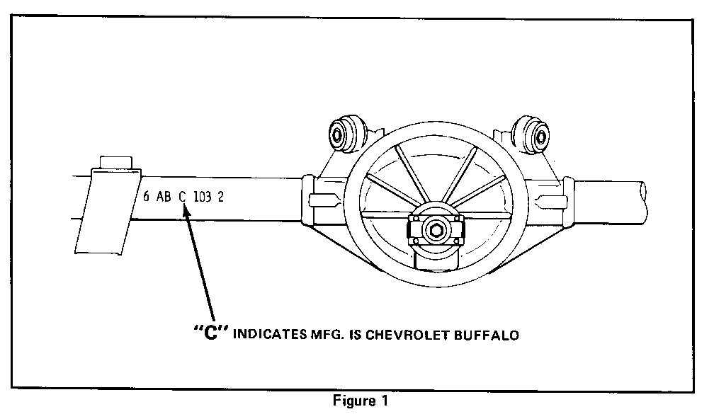
1. Raise the vehicle on a hoist. Locate the axle identification information stamped on the right front inboard side of the axle tube. Refer to Figure 1. It may be necessary to wire brush the area to make it legible.
2. If the manufacture code indicates a "C" as shown in Figure 1, go to Step 3 of this procedure. If other than a "C" proceed to step 13.
3. If the vehicle has less than 20,000 miles go directly to Step 8.
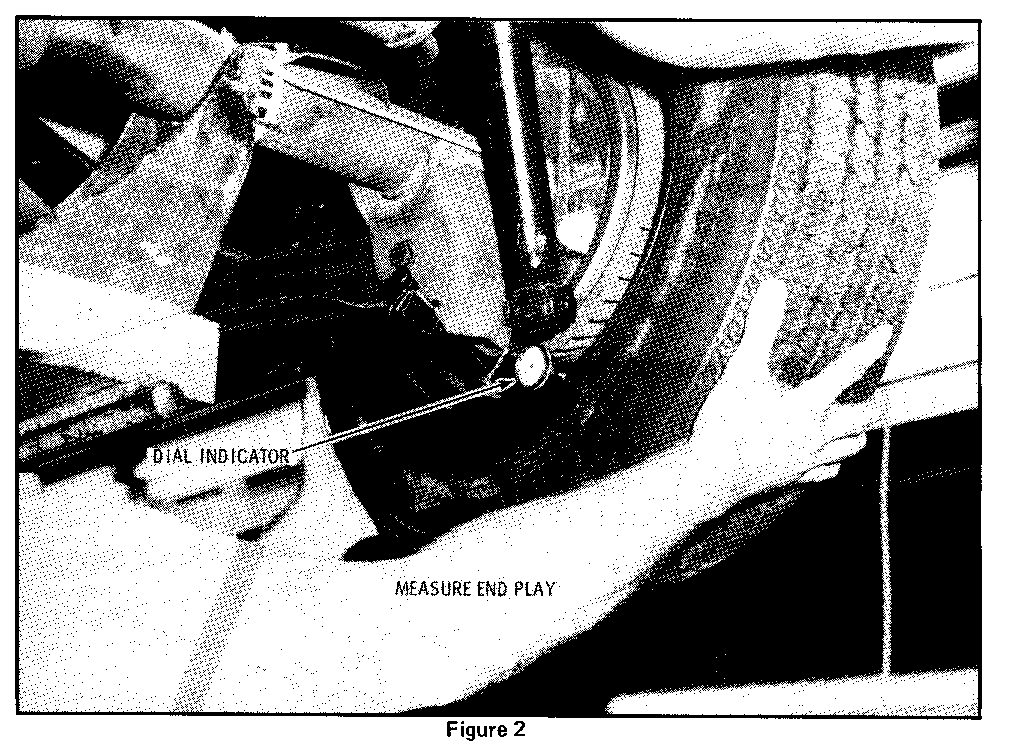
If the vehicle has greater than 20,000 miles, mount a dial indicator on the axle housing behind either rear wheel. Rest the indicator point against the back side of the wheel or the edge of the brake drum.
4. Measure the end play of each axle shaft by grasping the tire with both hands and pushing outboard until axle shaft is felt to bottom. Zero indicator. Refer to Figure 2.
5. Again grasp the tire with both hands and pull inboard until axle shaft is felt to bottom. Read he indicator, making certain that the reading is within the range of the indicator. Record the ndicator reading of each rear axle. Refer to Figure 2.
6. The readings obtained in Step 5 should be compared with the specifications in Chart 1.
CHART 1
Maximum Allowable End Play for Either Axle Shaft
Mileage Perform Step 8 If End Play is:
20,000 to 30,000 Greater than .030 30,000 to 45,000 Greater than .040 45,000 or Over Greater than .055
7. If the end play reading of both axle shafts EQUALS or is LESS than the end play specification in Chart 1, at the mileage indicated, no additional checking is required. Proceed to Step 13.
If the end play reading of either axle shaft EXCEEDS the end play specification in Chart 1, at the indicated mileage, the following steps should be performed.
8. Remove the axle carrier inspection cover and drain the lubricant.
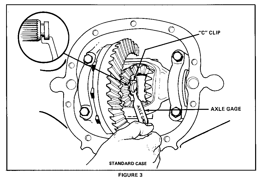
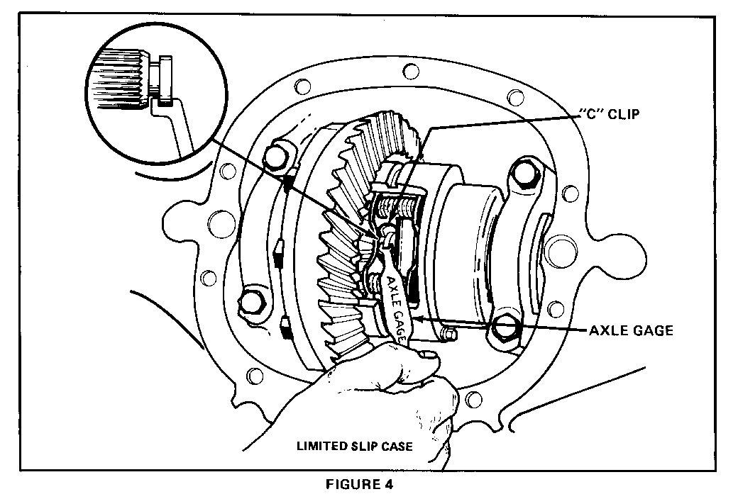
9. Each axle shaft button thickness must be measured using the Special Axle Button Gage Tool being shipped separately to the attention of the Service Manager (see Dealer Letter). In order to measure button thickness, the axle shafts must be pushed fully inboard and the "C" lock must be rotated so that the opening faces rearward to allow access for the gage. See Figures 3 and 4. The button thickness must be checked using both ends of the gaging tool. Refer to Chart 11 to determine the action required.
10. If necessary, the axle shaft and the differential pinion shaft should be replaced using the procedure in the applicable service manual. For part numbers, refer to "Parts Information" section of this bulletin.
NOTE: Should the pinion shaft lock screw break while removing, refer to the September 1983 Service Guild article for removal of the pinion cross shaft.
CHART II Pinion Shaft and Axle Shaft Replacement
Axle Shaft Button Thickness
Greater Than Less Than Mileage .190" .160" - .190" .160" ------- ----- ------------- ------ 0 to 20,000 Replace Pinion Replace Pinion Replace Pinion Shaft Shaft & Axle Shaft
20,000 to 75,000 No Part Replace Pinion Replace Pinion Replacement Shaft & Axle Shaft
Over 75,000 No Part No Part Replace Pinion Replacement Replacement & Axle Shaft
11. After completing above steps, verify that axle shaft end play is less than the maximum allowed in Chart II. If it is not, determine cause of end play, if possible, and contact your Zone Office for instruction.
CHART III
Maximum Allowable End Play For Either Axle Shaft After Performing Above Procedure
Mileage Standard Axle Limited Slip ------- ------------- ------------ To 45,000 .040 .065 Over 45,000 .055 .085
12. Install the axle carrier cover using a new cover gasket and fill housing with the proper lubrication. Lower hoist.
13. Raise hood to install a Completion Identification Label on the radiator fan shoud.
Each vehicle modified in accordance with the instructions outlined in this service procedure will require an identification label. Each label provides a space to include the bulletin number, the five (5) digit dealer code of the dealer performing the service, and the date the vehicle was serviced. This information may be inserted with a typewriter or ballpoint pen. Install the label on the radiator baffle where it is readily visible. Close hood.
PARTS INFORMATION
VERY FEW VEHICLES WILL REQUIRE PARTS (1 IN EVERY 200 VEHICLES INSPECTED). THEREFORE, LIMIT THE NUMBER OF PARTS BEING ORDERED TO PREVENT A PARTS SHORTAGE CONDITION. To ensure that parts will be obtained as soon as possible, they should be ordered from WDDGM on a C.I.O. order with NO special instruction code, but order on an advise code (2).
Description Part Number Quantity ----------- ----------- -------- Axle 551818 As Required Pinion Shaft - Use for Std. or G80 22507586 1 Limited Slip Differential Cover Gasket 551651 1 Lubricant 1052271 1 3/4qt. Lubricant Additive (Limited Slip Only) 1052358 4 oz.
Parts are to be retained for disposition by zone personnel.
WARRANTY INFORMATION
Operation Failure Code Labor Operation Labor Hours ---------- ------------- --------------- ----------- Inspect Axle Code No 96 V2470 .3 Further Action Required
Inspect Axle Code and 96 V2471 .3 Check Axle Shaft End Play
Inspect Axle Code, Check End 96 V2472 .5 Play and Button Thickness
Inspect Axle Code, Check End 96 V2473 .7 Play and Button Thickness. Replace One or Two Axle Shafts and/or Pinion Shaft
.1 hour for clerical administration may be added to the above operation.
Parts will be credited at dealer cost plus 30%. Refer to Part Information Section of this Bulletin.


General Motors bulletins are intended for use by professional technicians, not a "do-it-yourselfer". They are written to inform those technicians of conditions that may occur on some vehicles, or to provide information that could assist in the proper service of a vehicle. Properly trained technicians have the equipment, tools, safety instructions and know-how to do a job properly and safely. If a condition is described, do not assume that the bulletin applies to your vehicle, or that your vehicle will have that condition. See a General Motors dealer servicing your brand of General Motors vehicle for information on whether your vehicle may benefit from the information.
