CAMPAIGN: ENGINE COOLANT FAN RELAY MAY FAIL

CONDITION
General Motors has determined that some 1983 Oldsmobile Cutlass Cieras were assembled with an engine cooling fan relay that may fail. A failed relay can cause the fan motor to continue to operate with the ignition switch in the "Off" position, resulting in a discharged battery.
VEHICLES INVOLVED
Certain 1983 Cutlass Cieras equipped with 3.0L engines (LK9, VIN E) and air conditioning, within the following serial numbers:
ASSEMBLY PLANT BEGINNING UP TO AND INCLUDING -------------- --------- ------------------- Doraville DD386807 DD394985 Framingham DG300446 DG303476
Certain 1983 Cutlass Cieras equipped with 3.0L engines (LK9 VIN E) and standard heater (C-41) and Cutlass Cieras with 3.0L engine and standard heater (C-41) and heavy duty cooling (V-08) within the following serial numbers:
ASSEMBLY PLANT BEGINNING UP TO AND INCLUDING -------------- --------- ------------------- Doraville DD386807 DD409395 Framingham DG300446 DG306245
A number of vehicles within the serial number groups had relay(s) changed at the assembly plants prior to shipment. These corrected vehicles will not be on the vehicle listing.
DEALER ACTION
To prevent the possibility of this occurring, dealers are to perform the following action, as instructed in the Service Procedure section of this bulletin:
- Vehicles equipped with air conditioning, replace the fan high-speed relay with a heavy duty relay.
- Vehicles equipped with heater only, less heavy duty cooling, replace the fan single-speed relay with an improved relay.
- Vehicles equipped with heater only and heavy duty cooling, replace both the fan high-speed and low-speed relays.
Dealers are to service all vehicles subject to this campaign at no charge to owners, regardless of mileage, age of vehicle, or ownership, from this time forward.
Whenever a vehicle subject to this campaign is taken into your new or used vehicle inventory, or it is in your dealership for service in the future, you should take the steps necessary to be sure the campaign correction has been made before reselling or releasing the vehicle.
Owners of vehicles recently sold from your new vehicle inventory are to be contacted by the dealer, and arrangements made to make the required modification according to instructions contained in this bulletin.
SERVICE PROCEDURE
PART I - Installation of Relay and Jumper Harness Kit No. 25519237. Vehicles equipped with air conditioner or with heater only and heavy-duty cooling.
Some vehicles have a wire connected from the No. 4 terminal of the low speed-fan relay to ground at the radiator tie bar. This wire should be removed and discarded during the following procedure:
1. Raise hood and cover fender.
2. Remove the two (2) screws that attach left sheet metal brace to radiator upper tie bar. Loosen the brace rear attaching screw and route brace inward to expose area over the battery.
3. Remove the positive cable from battery. Cover positive terminal on battery with electrical tape.
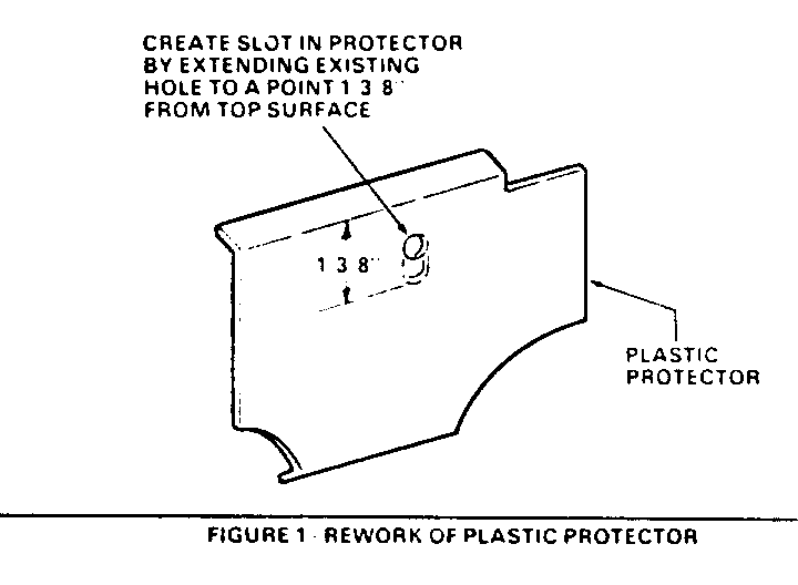
4. Remove plastic protector from upper tie bar and slot as shownn in Figure 1.
5. Remove screw retaining forward lamp and battery ground terminals to tie bar. Retain screw for use in Step 7. If there is a wire from the low-speed relay which is grounded by this screw, this wire should be removed and discarded.
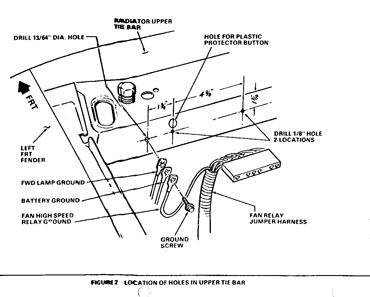
6. Drill two (2) 1/8" relay mounting holes in tie bar at locations shown in Figure 2. Use the new relay as a temptate, if required.
7. Drill one (1) 13/64" hole in tie bar and attach ground wire of the new jumper harness, along with forward lamp and battery ground wires, using screw removed in Step 5. Refer to Figure 2.
NOTICE: Electrical connectors are packed with special water resistant grease. Do not remove or wipe this grease from parts during installation of kit.
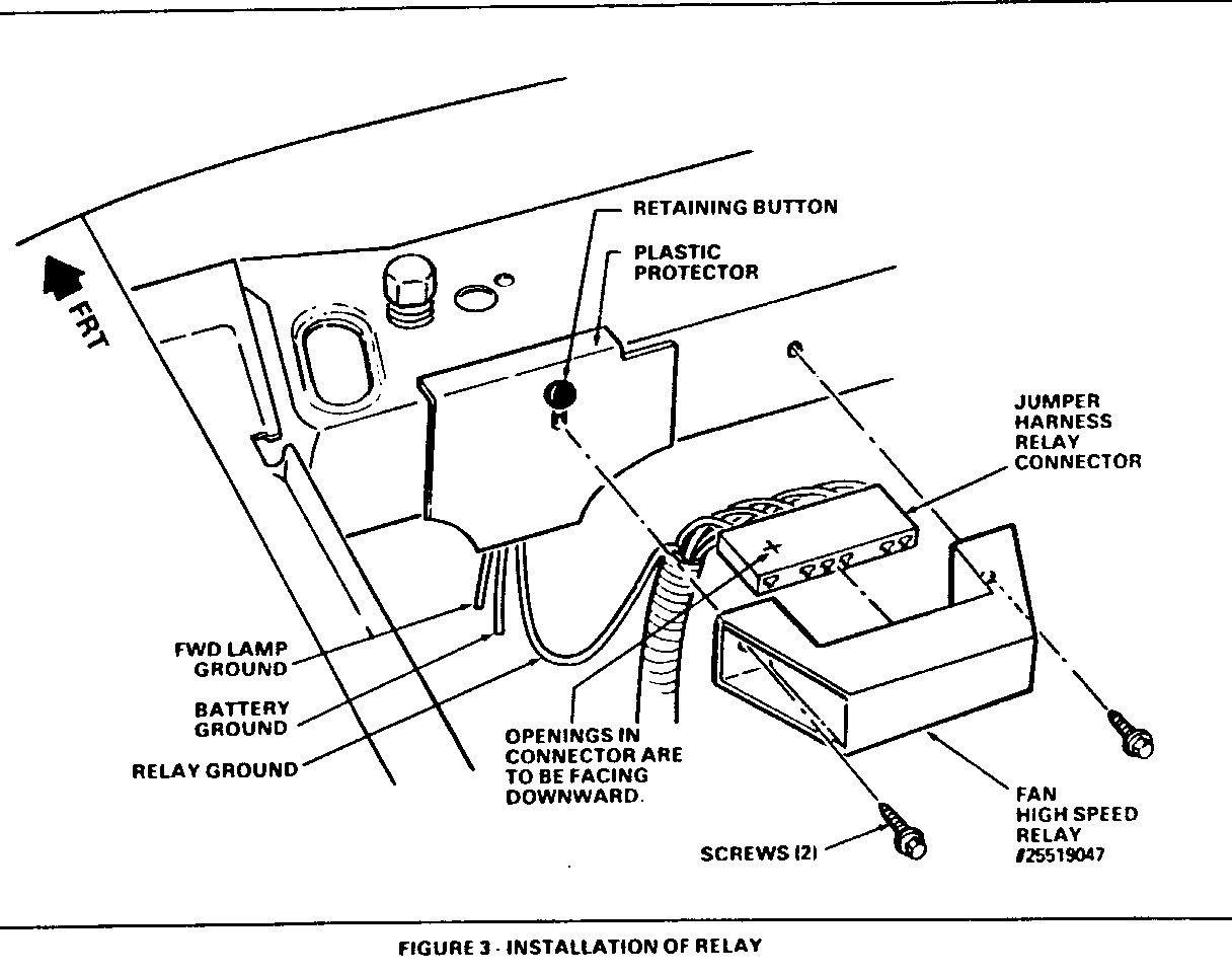
8. Reinstall plastic protector on tie bar, plug jumper harness connector on relay and attach relay to tie bar using furnished screws. Refer to Figure 3.
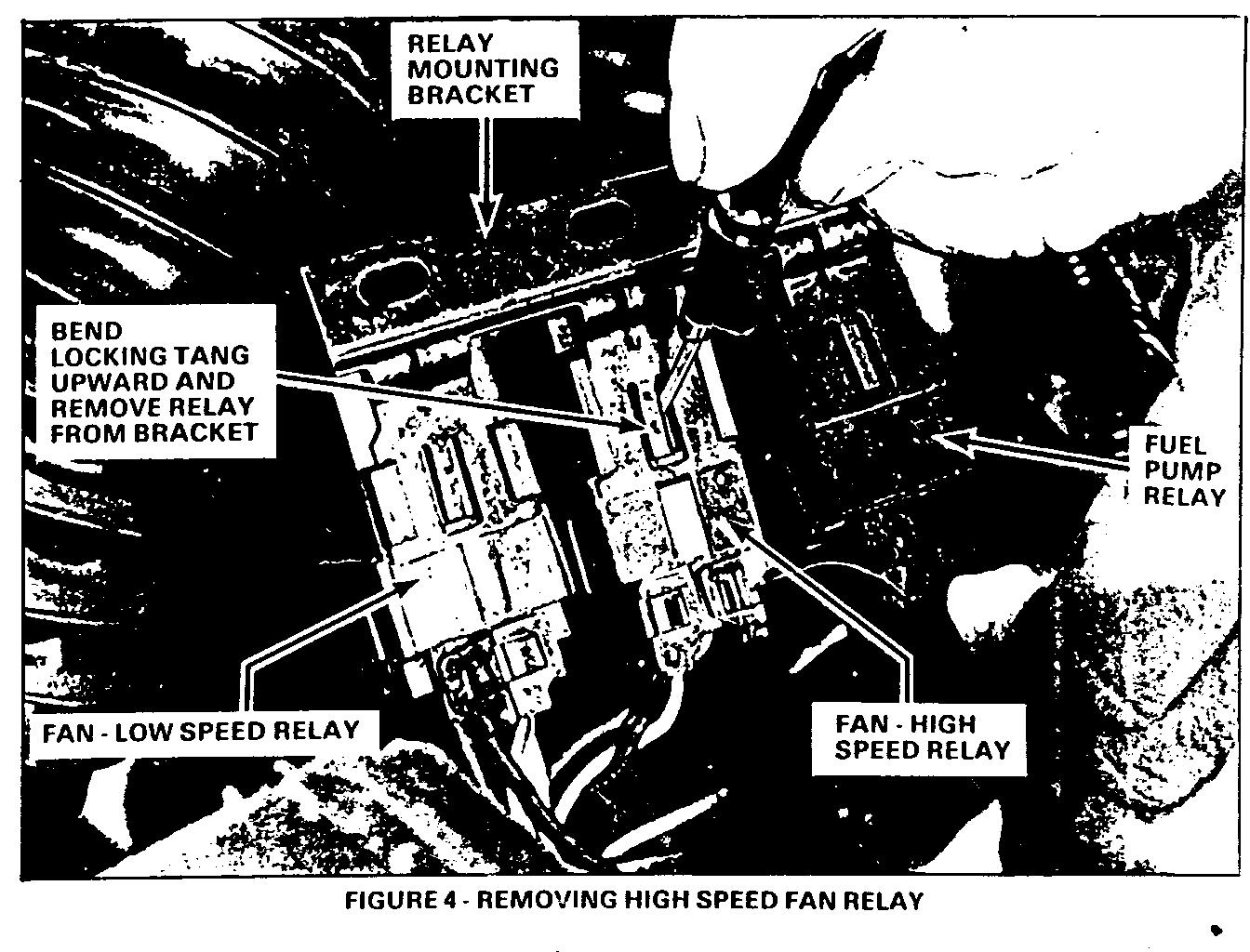
9. Remove the fuel pump, high and low-speed relay mounting bracket, from left wheel house. Remove the fan high speed (center) relay from bracket. Refer to Figure 4.
IF VEHICLE IS EQUIPPED WITH HEATER ONLY AND HEAVY-DUTY COOLING. PRIOR TO THE FOLLOWING STEP, INSTALL FAN SINGLE/LOW-SPEED RELAY AS INSTRUCTED IN STEPS 3,4 AND 5 OF PART II OF SERVICE PROCEDURE.
10. Assemble relay mounting bracket to wheelhouse.
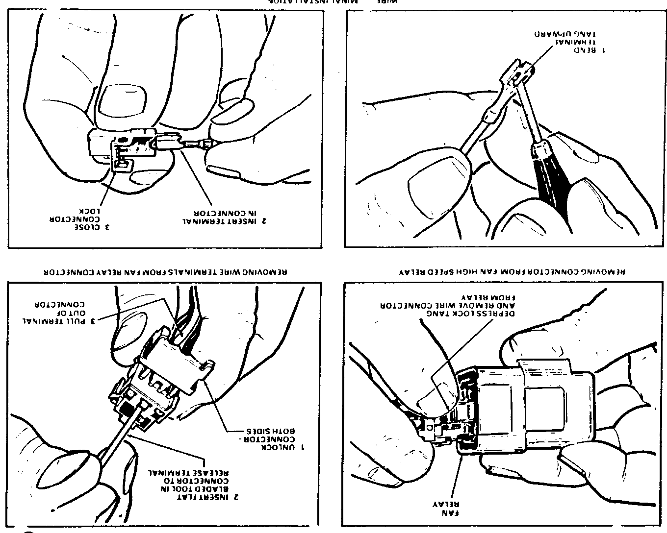
11. Remove wiring connector from fan high-speed relay. Unlock this connector, remove the four wire terminals and discard connector. Refer to Figure 5.
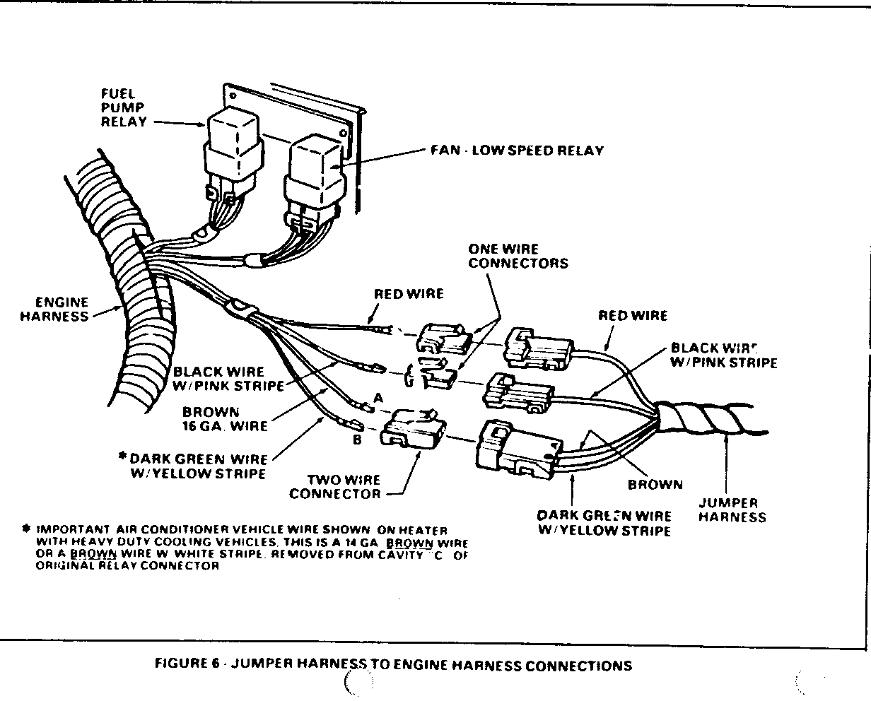
12. Install the four wire terminals removed in Step 10 into the three furnished connectors as shown, and plug the connectors into the jumper harness. Refer to Figure 6. Original wire colors must match the wire colors in the jumper harness, except for the wire removed from cavity "C" of original connector on vehicles with heater only and heavy-duty cooling. Refer to important note on Figure 6.
13. Check cooling fan high speed relay operation by grounding the relay jumper harness dark green with yellow striped wire. Any change from the following procedure could result in damage to the new relay.
a. Insert a jumper wire probe in relay jumper harrness connector cavity "B" so that probe contacts terminal of the dark green with yellow striped wire. Refer to Figure 6.
b. Attach the other end of jumper wire to a suitable ground (sheet metal screw, battery negative terminal, etc.).
c. Remove tape from battery positive terminal and reinstall positive cable.
d. Recheck to be sure you have a good connection between ground jumper and jumper harness green wire with yellow stripe.
e. Place air conditioner selector lever in the "OFF" position.
f. Turn ignition switch to "ON". Fan should run at high-speed. If fan does not operate, cause should be determined and corrected.
g. Allow fan to operate for a minimum of ten (10) seconds. Turn ignition off and remove jumper wire.
14. Reinstall left sheet metal brace front attaching screws and tighten the rear attaching screw. Be sure plastic conduit is on brace in area over battery.
15. Install campaign identification label as instructed in Part III.
PART II - Installation of Single/Low-Speed Relay Kit No. 25519249. Vehicles equipped with heater only.
1. Raise vehicle hood, cover fender, and remove battery positive cable.
2. Remove the fuel pump and fan relay mounting bracket from the left wheelhouse.
3. Lift up tang on bracket and remove fan single/low-speed relay. Disconnect wiring connector from relay. Unlock connector and remove the four wire terminals and discard connector. Refer to Figures 4 and 5. (Figures 4 and 5 show procedure for high-speed fan relay. Procedure is the same for single/low-speed relay except for location of relay on bracket.)
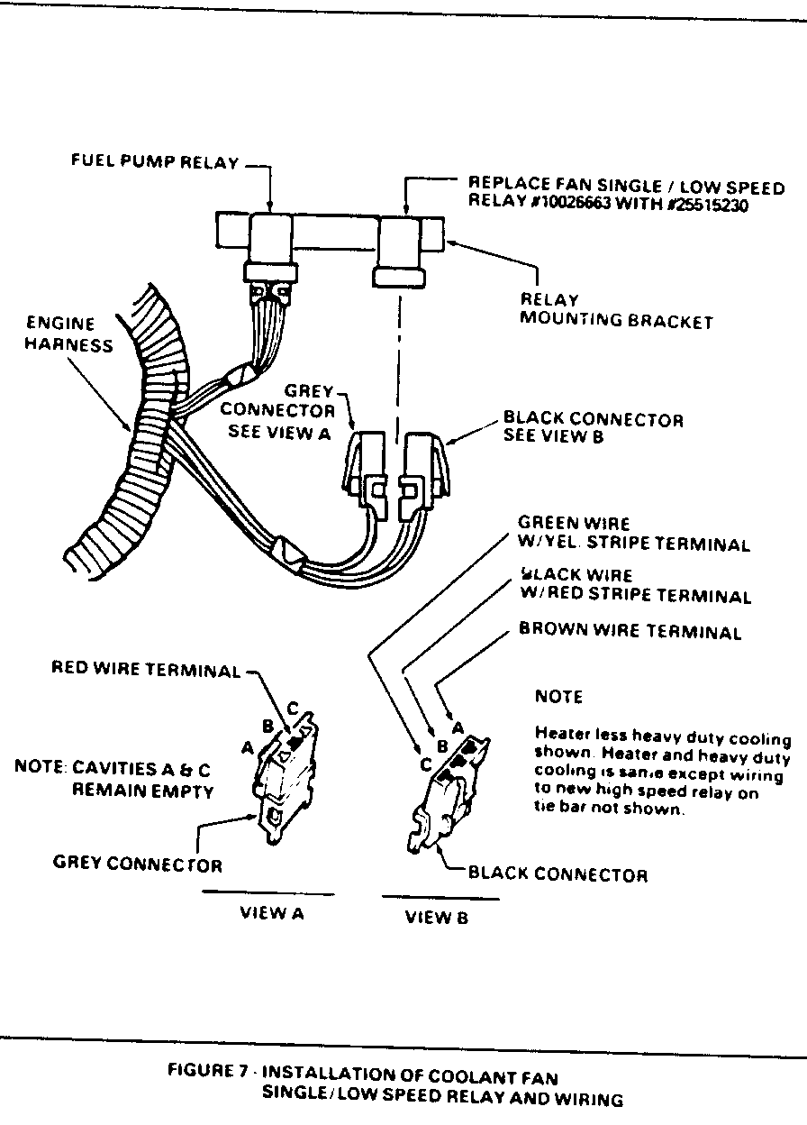
4. Insert the four wire terminals removed in Step 3 into the two connectors furnished in kit as shown in Figure 7. Plug these connectors onto new relay No. 25515230. Install relay on mounting bracket.
5. Check cooling fan single/low-speed relay operation by grounding the relay dark green with yellow striped wire.
Any change from the following procedure could result in damage to the new relay.
a. Insert a jumper wire probe in single/low-speed relay connector cavity so that probe contacts the terminal of the dark green with yellow striped wire. Refer to Figure 7.
b. Attach the other end of jumper wire to a suitable ground.
c. Connect battery positive cable.
d. Recheck to be sure you have a good connection between ground and relay green wire with yellow stripe.
e. Turn ignition switch to "ON". Fan should run at single/low-speed. If fan does not operate, cause should be determined and corrected.
f. Allow fan to operate for a minimum of ten (10) seconds. Turn ignition switch off and remove jumper wire.
6. Assemble relay mounting bracket to wheelhouse.
7. Install campaign identification label as instructed in Part III.
PART III - Install Campaign Identification Label
Each vehicle modified in accordance with the instruction outlined in this Service Procedure will require a Campaign Identification Label. Each label provides a space to include the compaign number, the five (5) digit dealer code of the dealer performing the campaign service, and the date vehicle was campaigned. This information may be inserted with a typewriter or ballpoint pen. When installing label, clean the surface of the radiator upper mounting support and apply the campaign label where it is readily visible.
PARTS INFORMATION
If your dealership has vehicles involved in this campaign, you will receive a printout of all vehicles shipped to your dealership. The printout will indicate what part kit(s) is required for each vehicle. For example:
If "A" is printed on the right hand side of the printout, vehicle is equipped with air conditioner (C-60), Relay Kit No. 25519237 is required.
If "N" is printed on the right hand side of the printout, vehicle is equipped with standard heater (C41) only, Kit No. 25519249 is required.
If "H" is printed on the right hand side of the printout, vehicle is equipped with standard heater (C41) and heavy-duty cooling (V-08), Kit No 22519237 and 25519249 are required.
High-Speed Relay Kit 25519237 contains the following parts:
1 High-Speed Relay No. 25519047 1 Jumper Harness 2 Relay Attaching Screws 2 Single-Wire Connectors 1 Two-Wire Connector
Single/Low-Speed Fan Relay No. 25519249 contains the following parts:
1 Single/Low-Speed Fan Relay No. 25515230 1 3-way Wire Connector, Gray in Color 1 3-way Wire Connector, Black in Color
To ensure these will be obtained as soon as possible, kits should be ordered from GM Parts (WDDGM) on a C.I.O. order with NO special instruction code, but order on an advise code (2).
Replaced parts must be held for disposition by Oldsmobile contact personnel.
WARRANTY INFORMATION
All dealers USING the terminal submission system are to submit campaign claims using their terminal. All other dealers are to submit campaign claims using the "yellow stripe" campaign cards. See page 59 of the Oldsmobile Claims Preparation Manual.
Operation Labor Operation Labor Time --------- --------------- ---------- Vehicles with A/C-Install V1730 .6 High-Speed Relay Kit - Part Number 25519237
Vehicles with Heater Only- V1731 .4 Install Single/Low Speed Relay Kit - Part Number 25519249
Vehicles with Heater Only V1732 .7 and Heavy Duty Cooling- Install Single/Low and High- Speed Relay Kits - Part Number 22519237 and 25519249
Parts will be credited at dealer cost plus 30%.
.1 hour for clerical administration will be added to the above operations.
General Motors bulletins are intended for use by professional technicians, not a "do-it-yourselfer". They are written to inform those technicians of conditions that may occur on some vehicles, or to provide information that could assist in the proper service of a vehicle. Properly trained technicians have the equipment, tools, safety instructions and know-how to do a job properly and safely. If a condition is described, do not assume that the bulletin applies to your vehicle, or that your vehicle will have that condition. See a General Motors dealer servicing your brand of General Motors vehicle for information on whether your vehicle may benefit from the information.
