Tools Required
Notice: Do not clean the starter motor parts in a degreasing tank. Soaking parts
will dissolve the permanent lubrication and may damage the electrical
insulation. This will shorten starter motor life.
Starter Solenoid Inspection
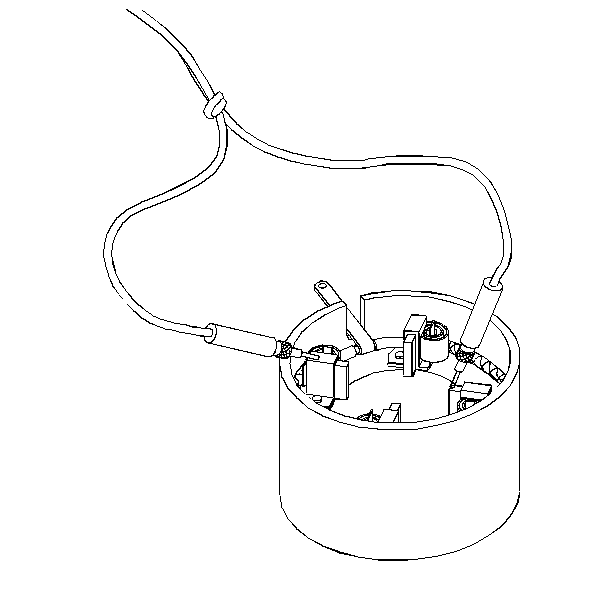
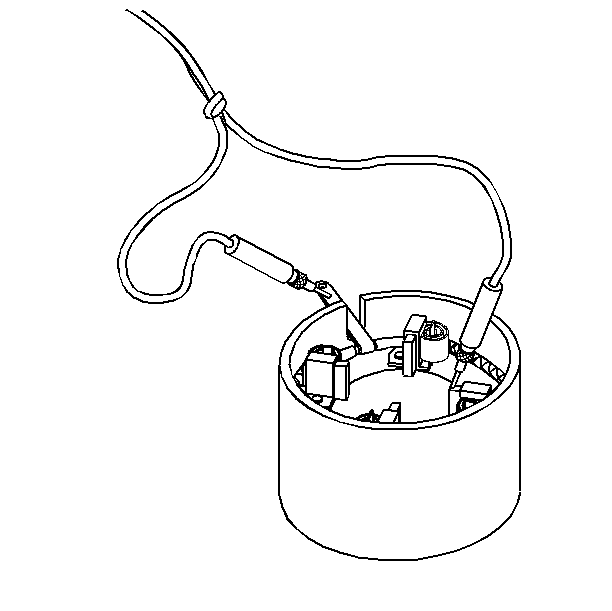
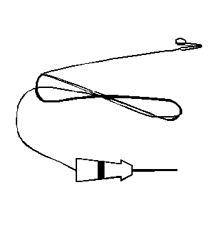
- Inspect the solenoid for grounds using a self-powered test lamp J 21008-A
.
- If the solenoid does not pass the following tests, install a new
solenoid.
| 2.1. | Connect J 21008-A
between the BAT terminal and the metal housing (ground). |
| 2.2. | The lamp should not light, meaning that the terminal is not grounded. |
| 2.3. | Connect J 21008-A
between the S terminal and the metal housing. |
The lamp should light.
| 2.4. | Connect J 21008-A
between the M terminal and the S terminal, or connect the test lamp
between the M terminal and the metal housing. |
The lamp should light.
Notice: To prevent overheating of the solenoid pull-in winding, do not leave
the winding energized for more than 15 seconds. The current draw will decrease
as the winding temperature increases.
- Inspect the hold-in winding and the pull-in winding.
Important: Before testing, the solenoid must be removed from the starter motor,
or the field lead must be removed from the terminal on the solenoid.
- In order to test both windings, perform the following procedure:
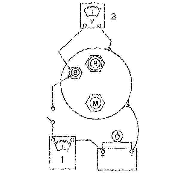
| 4.1. | Connect a multimeter in series with a 12 V battery positive
terminal, and the switch S terminal on the starter solenoid. |
| 4.2. | Connect the J 39200
to the S terminal on the starter solenoid and to the negative battery
terminal. |
| 4.3. | Connect the carbon pile (variable resistance) across the battery. |
| 4.4. | Ground the solenoid motor M terminal. |
| 4.5. | Adjust the voltage to 10 V and observe the multimeter reading. |
| 4.6. | The reading should be between 60-85 amperes. |
| • | A higher multimeter reading means that the winding is shorted
or grounded. |
| • | A lower multimeter reading means that there is excessive resistance
in the winding. |
| 4.7. | The J 39200
reads
the winding resistance, and measures in tenths of an ohm. |
| 4.8. | Dividing the voltage by the amperes (voltage/amperes), determines
coil resistance. Refer to Starter Motor Usage Table. |
Drive Inspection
- Check pinion teeth for cracks or excessive wear. Replace the drive
if these conditions are found.
- Inspect the flywheel for similar damage.
- Inspect the drive assembly for slipping before disassembling from
armature.
- Wrap armature in a shop cloth to protect it damage.
- Clamp the armature in vise just tight enough to hold firmly.
- Use a 12-point deep socket and a torque wrench to turn the pinion.
| • | If the pinion does not turn freely in the overrunning direction
(clockwise), replace the drive. |
| • | Pinion should lock when turned in the counterclockwise direction
and should withstand a torque of 68 N·m (50 lb ft).
If the drive pinion slips, replace the drive. |
- Refer to Starter Motor Disassembly to remove the drive from the
armature.
Armature Inspection
- Clean all parts by wiping with a dry cloth.
- Inspect the bushing or the armature bearing fit in the following
locations:
| • | The shift lever housing |
| • | The drive end frame housing (If the bushings or the bearings are
damaged, install new ones.) |
- Lubricate the bushings before assembling the starter motor.
| • | Avoid over lubrication. |
| • | Do not lubricate the roller bearings. |
| • | The roller bearings are permanently lubricated when manufactured. |
- Inspect the armature shaft for runout or scoring. If the condition
of the armature shaft is in doubt, install a new armature.
- Inspect the commutator for discolored or uneven conductors.
| • | Do not turn the commutator on a lathe. |
| • | Do not undercut the insulation. |
| • | Clean the commutator with No. 400 grain polishing cloth. |
| • | Blow away any copper dust. |
- If the commutator can not be cleaned satisfactorily, install a
new armature.
- Inspect the armature for short circuits using the following procedure:
| • | Rotate the armature in a growler. |
| • | Use a steel strip (such as a hacksaw blade) held on the armature,
parallel to the shaft. |
| • | If a short circuit is detected, the steel strip will vibrate over
the area. |
| • | Consult the growler manufacturer's instructions for more information. |
| • | Short circuits between the commutator bars can be produced by
brush dust or copper dust. |
- Inspect the armature for opens as follows:
| • | Look for loose connections where the conductors join the commutator
bars. |
| • | Poor connections cause arcing. |
| • | Arcing causes burning of the commutator. |
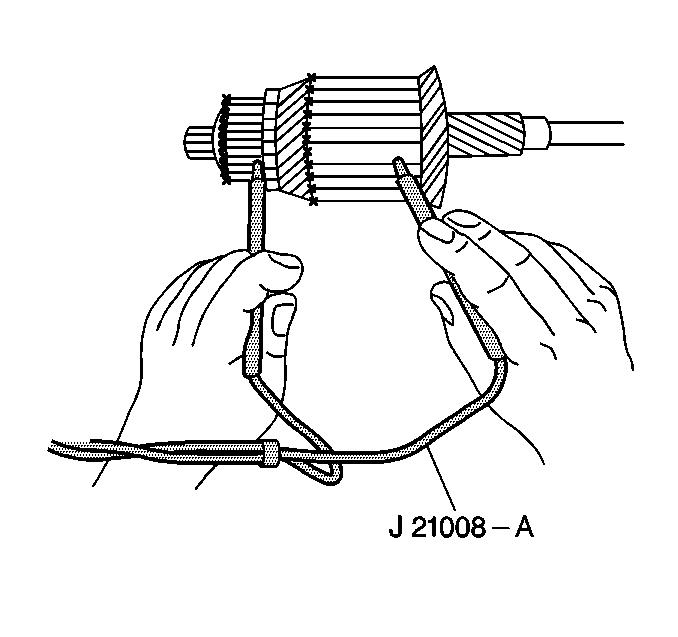
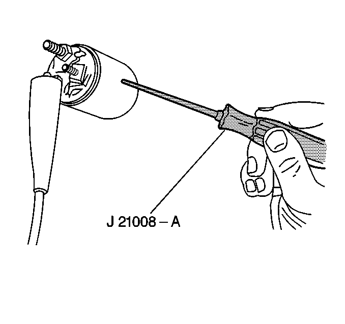
- Inspect the armature for grounds with a self-powered test lamp (continuity
tester). Use J 21008-A
.
| • | Place one test probe on the commutator. |
| • | Place the other test probe on the armature core or shaft. |
| • | If the test lamp lights, the armature is grounded. Replace any
grounded or shorted armature. |
Brush Holder Assembly Inspection
- Inspect the brushes for wear. If the brushes are worn to half
the size of a new brush, replace the assembly.
- Inspect the holders for dirt or damage. Make sure that the brushes
move freely and do not bind in the holders.
- Inspect the brush springs for distortion or discoloring.
| • | Repair any damaged brush springs, as necessary. |
| • | If the brush springs are weak, bent or discolored, replace the
field and frame assembly. |
Frame and Field Inspection
- Inspect the field coils.
| • | Look for burned or damaged insulation. |
| • | Look for damaged connections. |
| • | If the condition of the coils is doubtful, replace the field and
frame assembly. |
- Inspect the field coils for grounds.
| • | Connect the two leads from the J 21008-A
between the field frame and the field connector. |
| • | Be sure that the brush ends do not contact the field frame. |
| • | If the test lamp lights, the field coils are grounded. |
| • | Install a new field and frame assembly. |
- Inspect the field coils for opens.
| • | Connect the two leads from the J 21008-A
between the field connector and each of the positive brushes. |
| • | If the test lamp does not light at both brushes, then the fields
are open. |
- Inspect the field coils for shorts.
| • | Shorts are indicated if the starter motor runs poorly after all
other inspection procedures are complete. |
| • | If shorted, replace the frame and field coils as an assembly. |
