CAMPAIGN: REAR ENG LIFT/COIL MOUNTING BRKT AND COIL WIRE

MODELS/YEARS: CERTAIN 1987 FIRENZA MODELS EQUIPPED WITH 2.0L LT2 (VIN CODE K) ENGINE
CONDITION
General Motors has determined that some 1987 Firenza models may experience fatigue fracture of the rear engine lift bracket. The ignition coil and coil bracket is mounted to the rear engine lift bracket. If the lift bracket fractures, the coil may become unsupported. This condition may ultimately result in engine misfire and possible loss of engine operation.
Additionally, high frequency magnetic coupling between the ignition coil and distributor coil magnetic pickup can result in extra pulses in the RPM reference signal. This condition may cause extended cold cranking/no start, pop back during cranking and/or occasional "Service Engine Soon" light with stored code 42.
VEHICLES INVOLVED
Certain 1987 Firenza models equipped with 2.0L LT2 (VIN Code K) engines within the following vehicle breakpoints:
Plant Beginning Through and Including Service Required ----- --------- --------------------- ---------------- Leeds Start of Production HK 311896 Lift Bracket Pencil Brace and Coil Wire Shield
Leeds H K311897 HK 320176 Coil Wire Shield Only
DEALER ACTION
To protect against fatigue fracture of the rear engine lift bracket, the lift bracket will be inspected and, if necessary, replaced. Additionally, a pencil brace (service kit) will be installed as required on involved vehicles.
To prevent the possibility of magnetic coupling between the ignition coil and distributor coil magnetic pickup, a coil wire shield will be installed on all involved vehicles.
Dealers are to service all vehicles subject to this campaign at no charge to owners, regardless of mileage, age of vehicle, or ownership from this time forward.
Whenever a vehicle subject to this campaign is taken into your new or used vehicle inventory, or it is in your dealership for service in the future, you should take the steps necessary to be sure the campaign correction has been made before reselling or releasing the vehicle.
Owners of vehicles recently sold from your new vehicle inventory are to be contacted by the dealer and arrangements made to make the required modification according to instructions contained in this bulletin.
SERVICE PROCEDURE
1. Install fender blanket on left fender and disconnect negative battery cable.
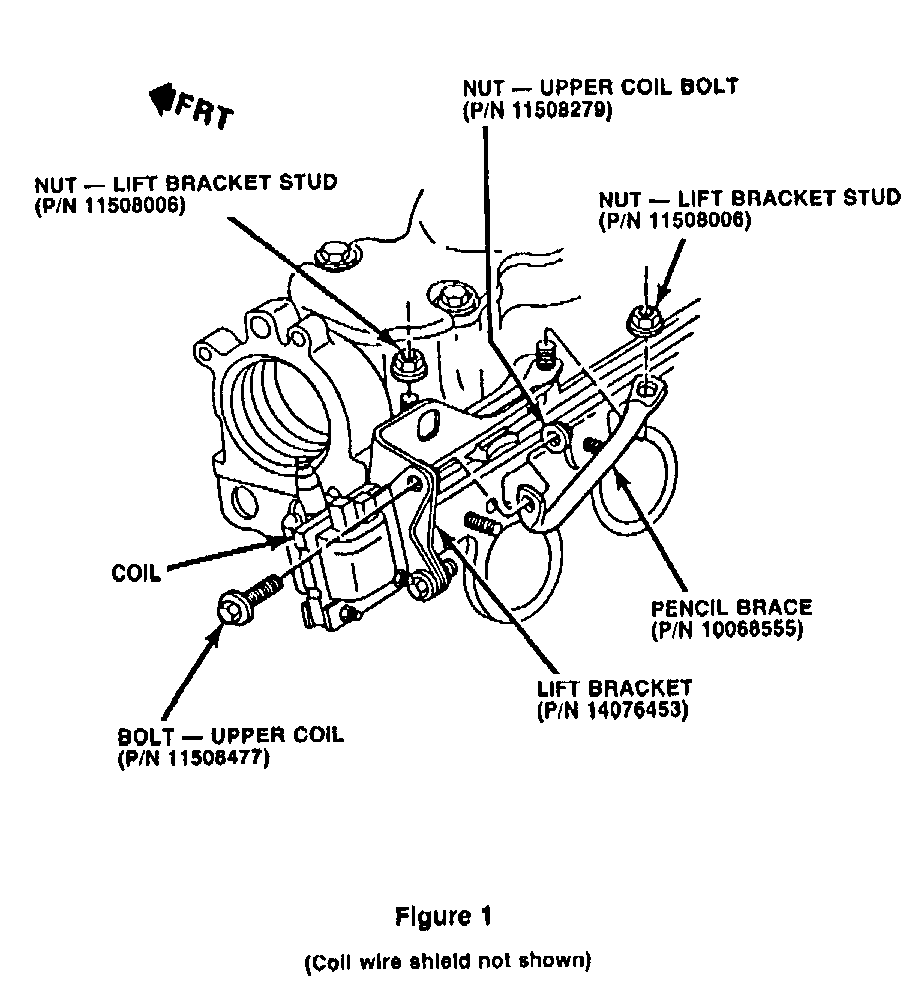
2. Remove air cleaner and inspect for pencil brace (see Figure 1). If pencil brace is NOT present, follow instructions for "PENCIL BRACE AND COIL WIRE SHIELD REQUIRED" otherwise follow instructions for "COIL SHIELD ONLY REQUIRED" as described below.
PENCIL BRACE AND COIL WIRE SHIELD REQUIRED
3. Disconnect electrical wiring from coil.
4. Remove upper existing coil bracket bolt (20 mm long) and loosen lower existing coil bolts.
5. Remove two (2) lift bracket nuts and discard.
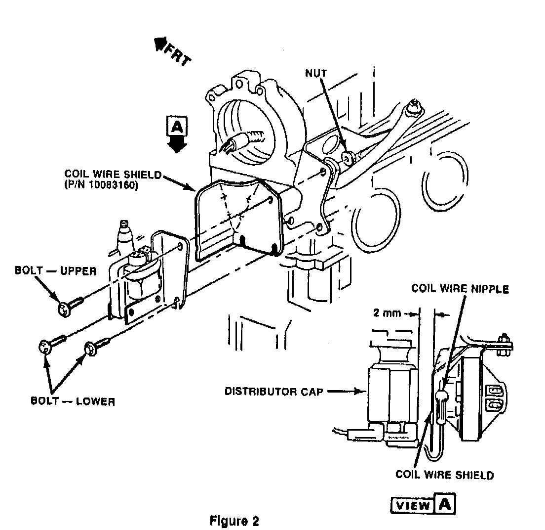
6. Remove lift bracket from engine and inspect for signs of a fatigue type crack appearing between the two (2) mounting stud holes. If a crack is present, replacement of lift bracket (Part Number 14076453) is required. Transfer lower coil bolts, coil and add coil wire shield to new bracket (see Figure 2).
7. Install new coil bracket bolt (top) (30 mm long) and attach lift bracket (pencil)-brace and nut from service kit (see F igure 1).
8. Position lift bracket, coil and coil wire shield on engine and attach end of pencil brace to front lift bracket stud.
9. Install new lift bracket nuts (washer faced) to studs.
10. Torque coil bracket nut first to position pencil brace 20-30N.m (15-22 lbs.ft.).
11. With shield in position, insure at least 2. mm clearance to the distributor cap (see Figure 2, View A). Bend engine lift bracket if required for minimum clearance. SHIELD MUST NOT CONTACT DISTRIBUTOR CAP.
12. Torque lift bracket nuts 40-60 N.m (30-45 lbs.ft.).
13. Torque lower coil bolts 20-30 N.m (15-22 lbs.ft.).
14. Connect electrical wiring at coil. COIL WIRE NIPPLE MUST NOT CONTACT SHIELD.
15. Install air cleaner.
16. Connect negative battery cable. Remove fender blanket.
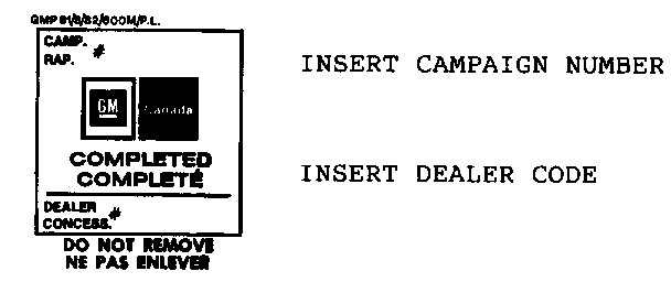
17. Install campaign identification label.
COIL WIRE SHIELD ONLY REQUIRED
3. Remove upper existing coil bolt.
4. Loosen lower existing coil bolt.
5. Install shield (see Figure 2).
6. Reinstall existing upper coil bolt and hand tighten.
7. Hand tighten lower coil bolts.
8. With shield in position, insure at least 2 mm clearance to the distributor cap (see Figure 2, View A). Bend engine lift bracket if required for minimum clearance. SHIELD MUST NOT CONTACT DISTRIBUTOR CAP.
9. Torque upper and lower coil bolts 20-30 N.m (15-22 lbs.ft.).
10. Connect electrical wiring at coil. COIL WIRE NIPPLE MUST NOT CONTACT SHIELD.
11. Install air cleaner.
12. Connect negative battery cable. Remove fender blanket.
13. Install campaign identification label.
CAMPAIGN IDENTIFICATION LABEL
Each label provides space to print the campaign number, and the five (5) digit dealer code of the dealer performing the campaign. Insert this information with a typewriter or ballpoint pen. When installing label, clean and dry the surface of the radiator support tie bar and apply the campaign label where it is readily visible.
PARTS INFORMATION
To ensure parts are obtained as soon as possible, order them from GM Service Parts Operations (GMSPO) on a C.I.O. order, with NO special instruction code, but order on an advise code (2). Use the following part numbers:
Description Part Number Quantity Per Vehicle
Rear Engine Lift 10068556 1 (As required) Bracket Service Kit*
Rear Engine Lift Bracket** 14076453 1 (As required)
Coil Wire Shield 10103509 1 Service Kit***
* Service Kit consists of: (1) Part Number 11508279 Nut, (1) Part Number Part Number 11508006 Nut, (1) Part Number 10068555 Pencil Brace, and (1) Part Number 10068560 instruction Sheet.
** It is estimated that only 11% of the vehicles requiring a pencil brace will also require lift bracket replacement, order parts accordingly.
*** Service Kit Consists of: (1) Part Number 10083160 Shield and (1) Part Number 10103508 Instruction Sheet.
WARRANTY CLAIM INFORMATION
PC PART-NO. TOT-PTS TC LAB-OP LHRS ST SUBLET -- --------- ------- -- ------ ---- -- ------ Install Pencil Brace and Coil Wire Shield 96 V4110 0.5 .1* --
Replace Engine Lift Bracket, install Pencil Brace and Coil Wire Shield 96 V4111 0.5 .1* -- install Coil Wire Shield Only 96 V4112 0.3 .1* --
* Allowance for clerical adminstration.
Parts allowance: Current dealer price, plus 30%.


General Motors bulletins are intended for use by professional technicians, not a "do-it-yourselfer". They are written to inform those technicians of conditions that may occur on some vehicles, or to provide information that could assist in the proper service of a vehicle. Properly trained technicians have the equipment, tools, safety instructions and know-how to do a job properly and safely. If a condition is described, do not assume that the bulletin applies to your vehicle, or that your vehicle will have that condition. See a General Motors dealer servicing your brand of General Motors vehicle for information on whether your vehicle may benefit from the information.
