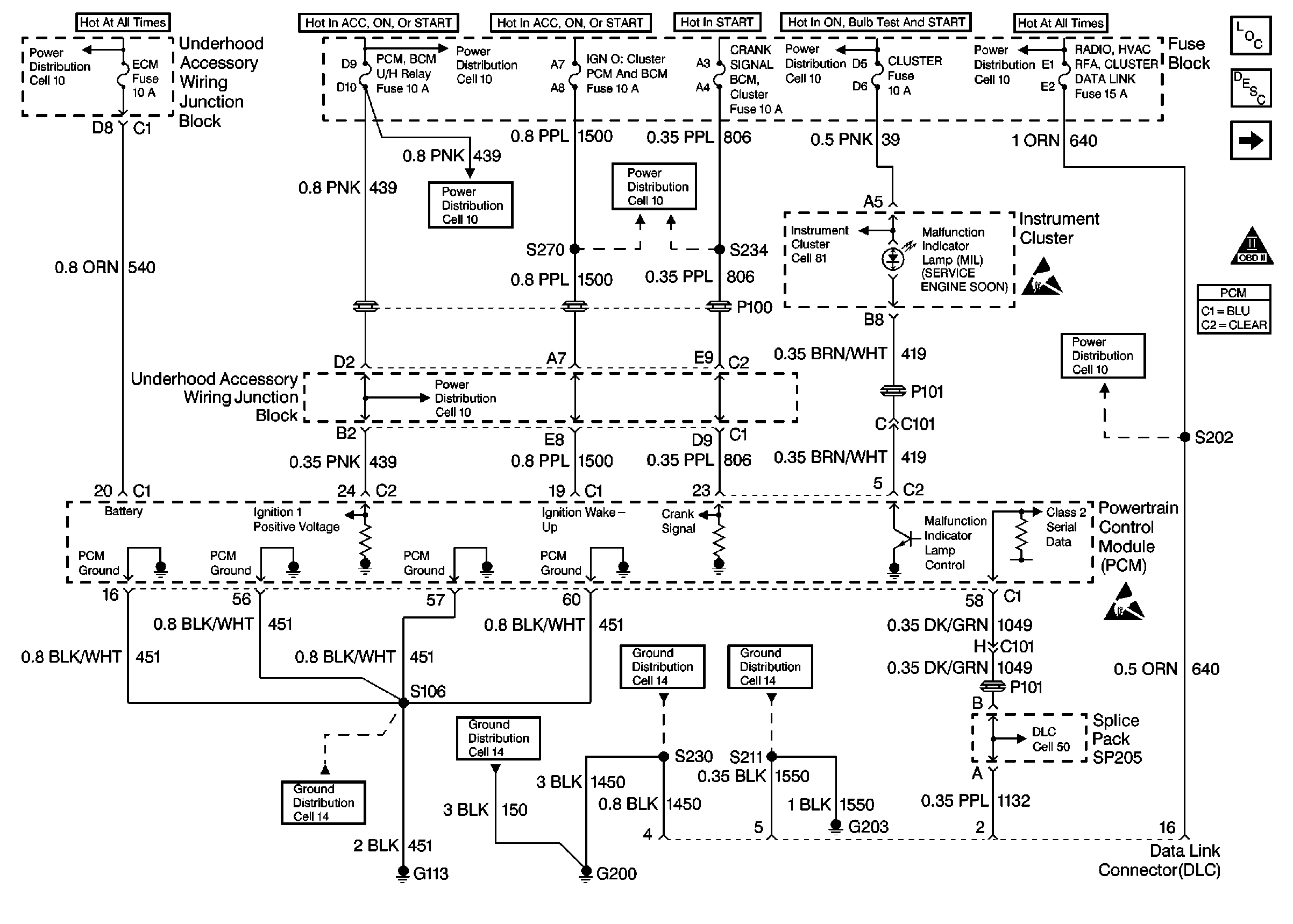
| Figure 1: |
Power, Ground, DLC and MIL
|
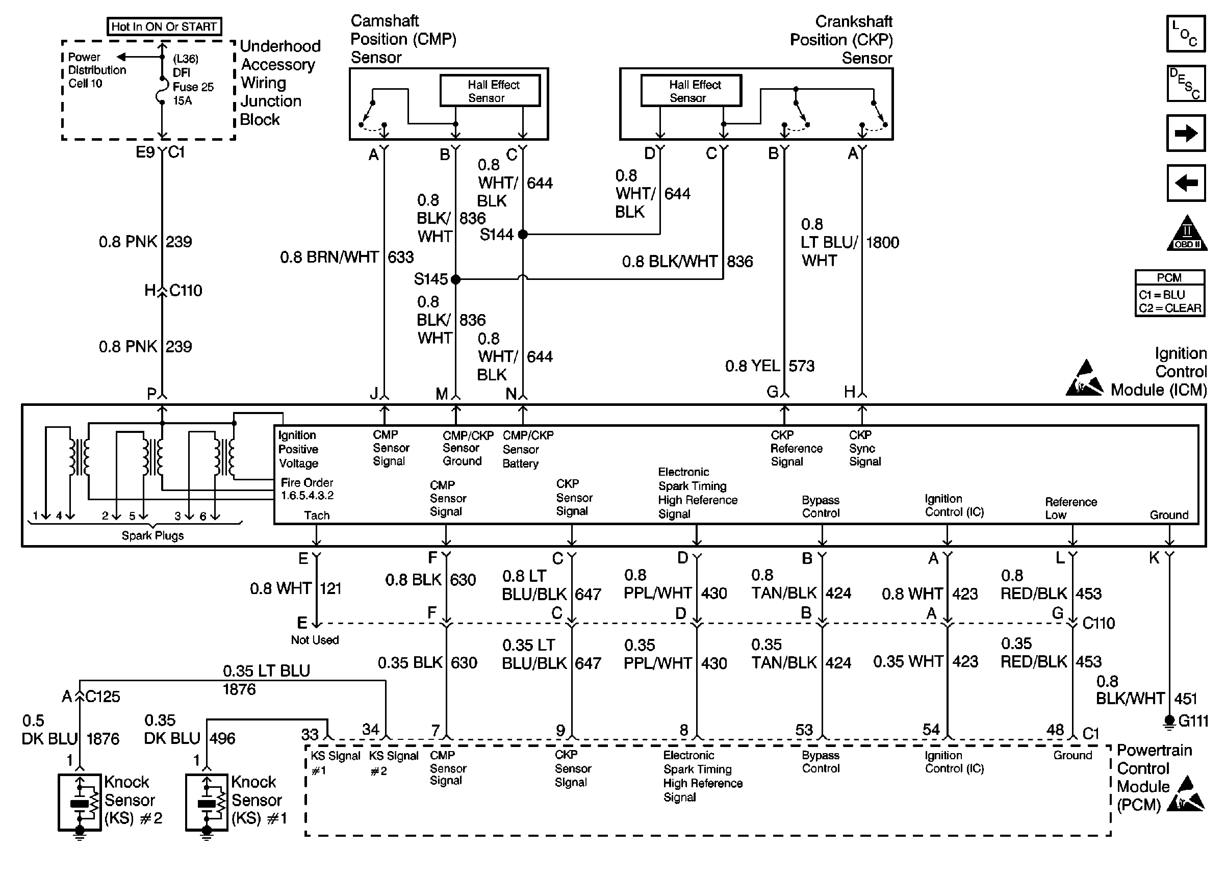
| Figure 2: |
Ignition Control Module, CMP and CKP
|
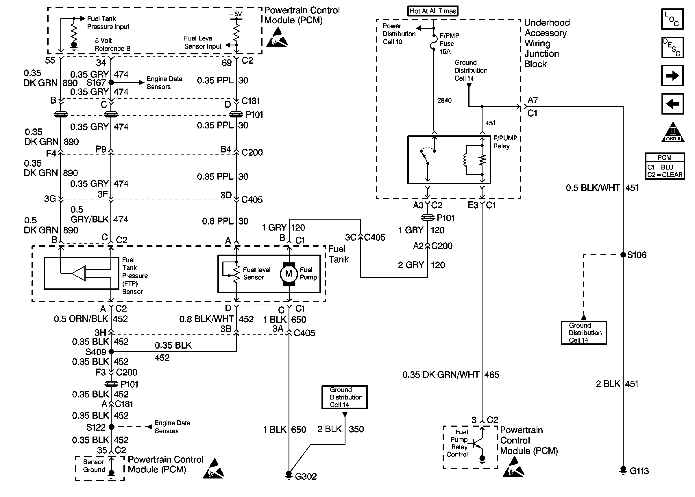
| Figure 3: |
Fuel Pump and Fuel Level Sensors
|
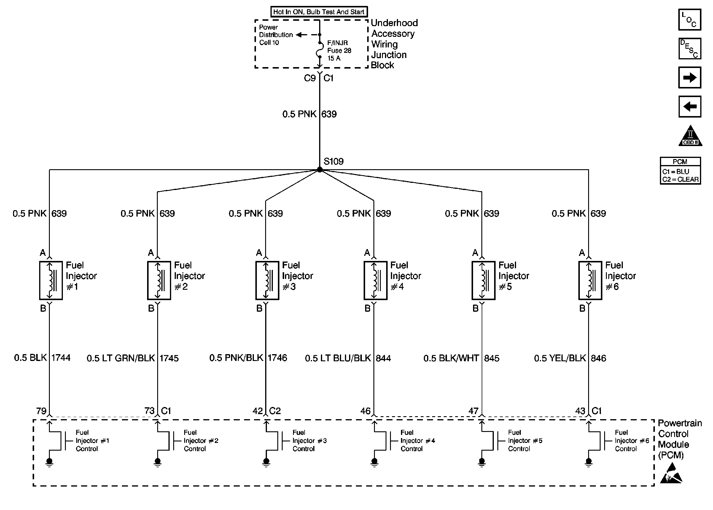
| Figure 4: |
Fuel Injectors
|
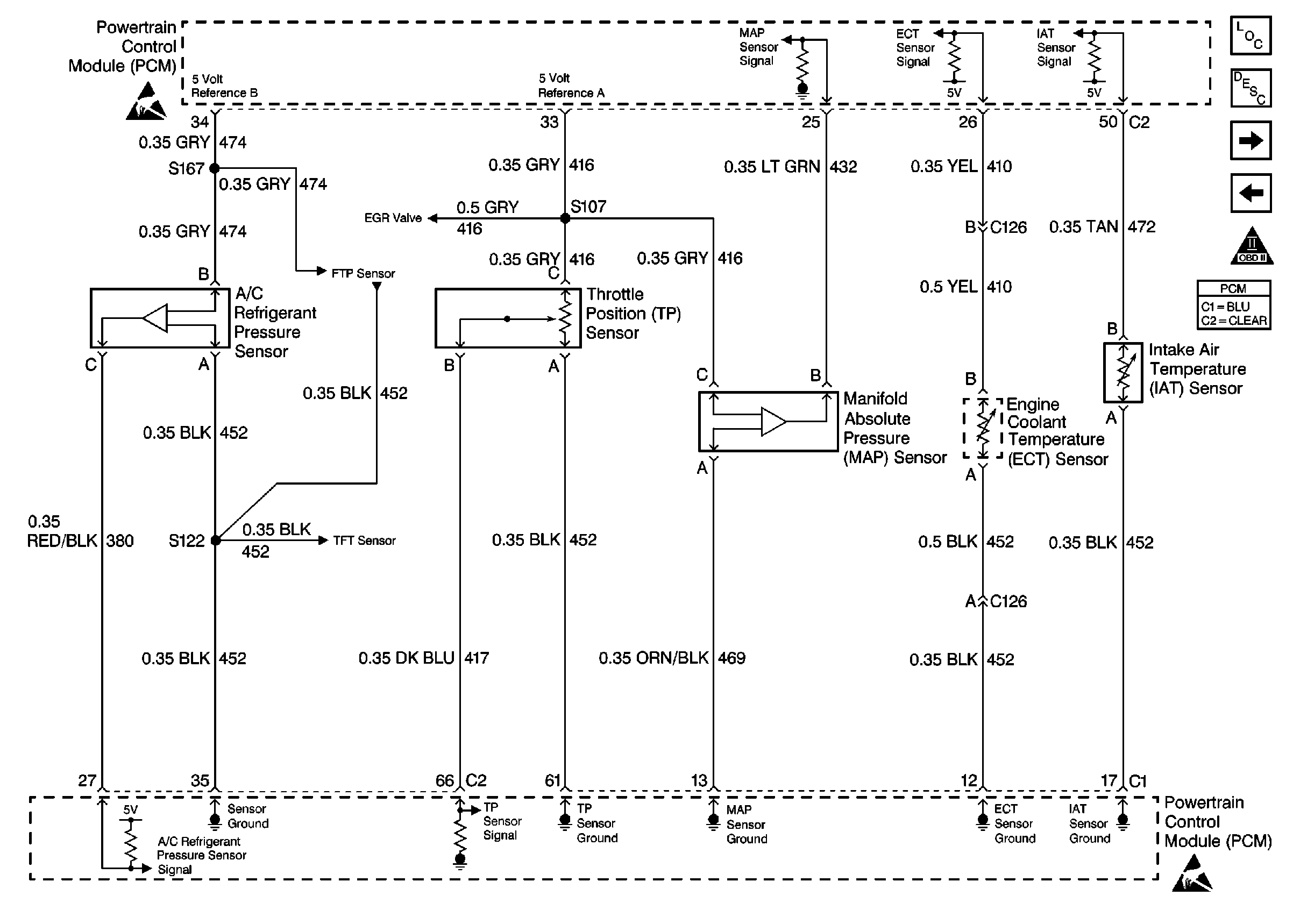
| Figure 5: |
Engine Data Sensors
|
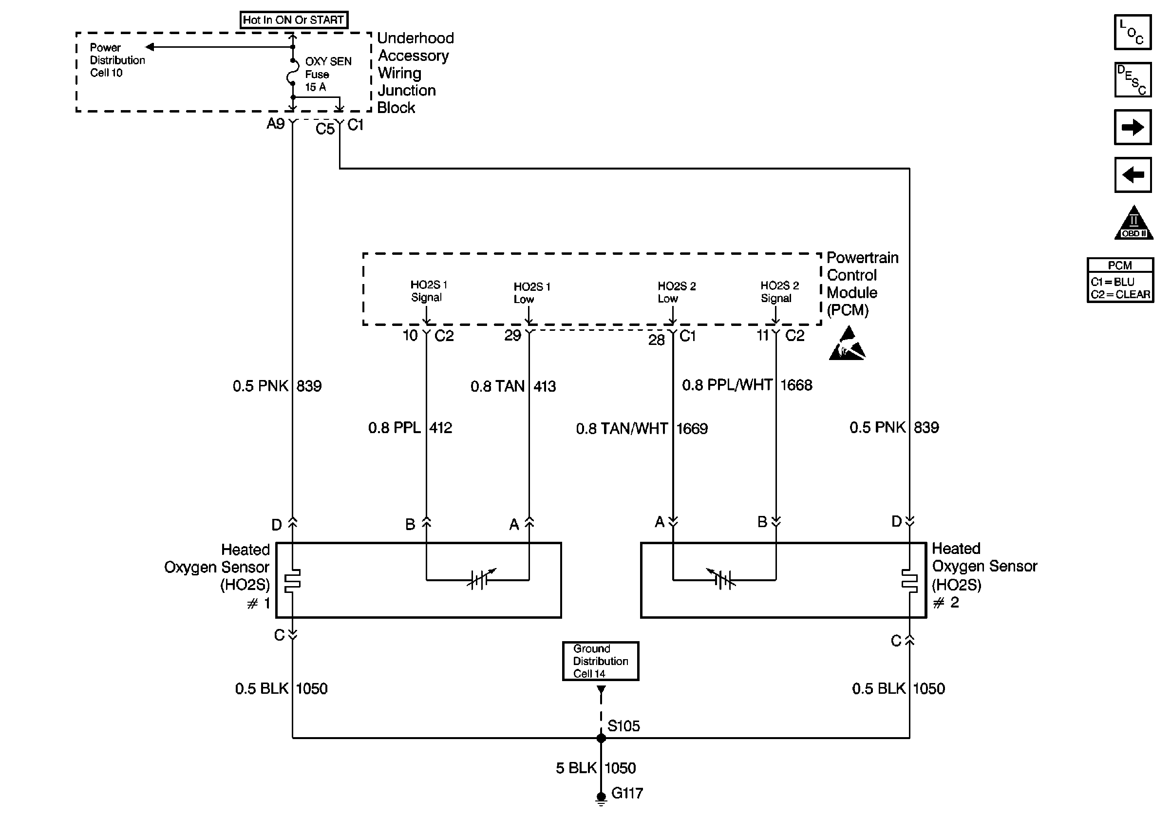
| Figure 6: |
Heated Oxygen Sensor (HO2S) #1 and #2
|
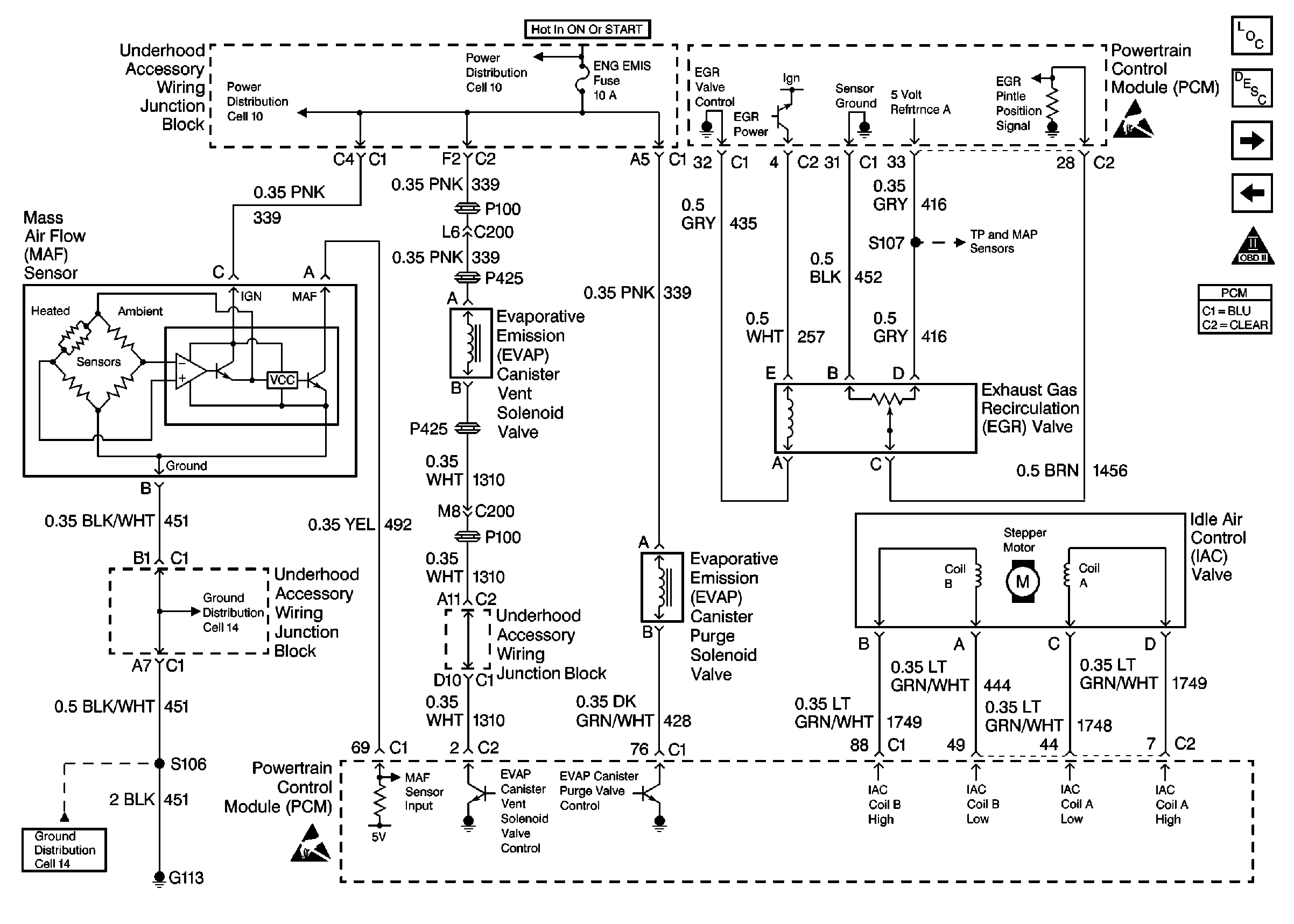
| Figure 7: |
MAF, IAC, EGR, and EVAP
|
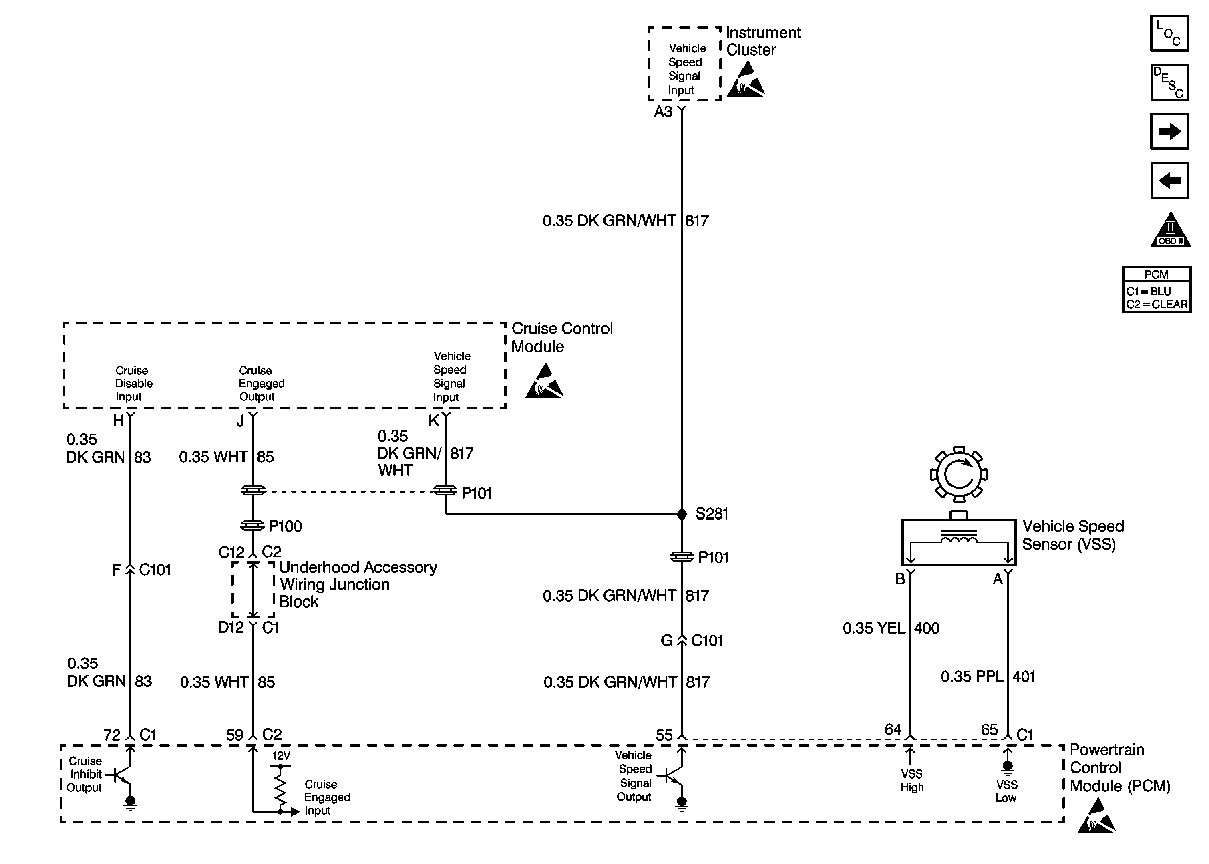
| Figure 8: |
Cruise Control Module and VSS
|
| Figure 9: |
Indicators
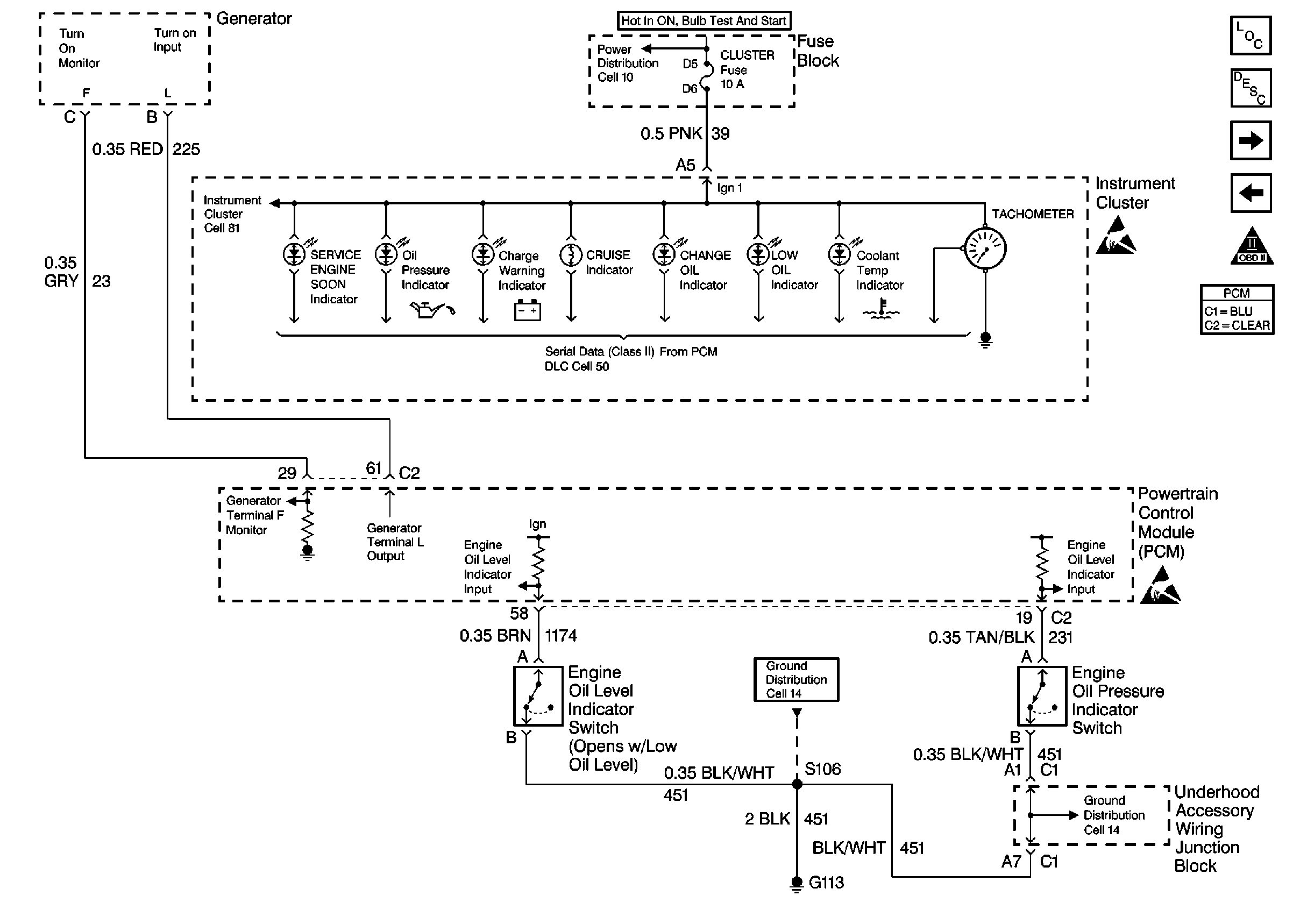
|
| Figure 10: |
Transaxle Range Switch
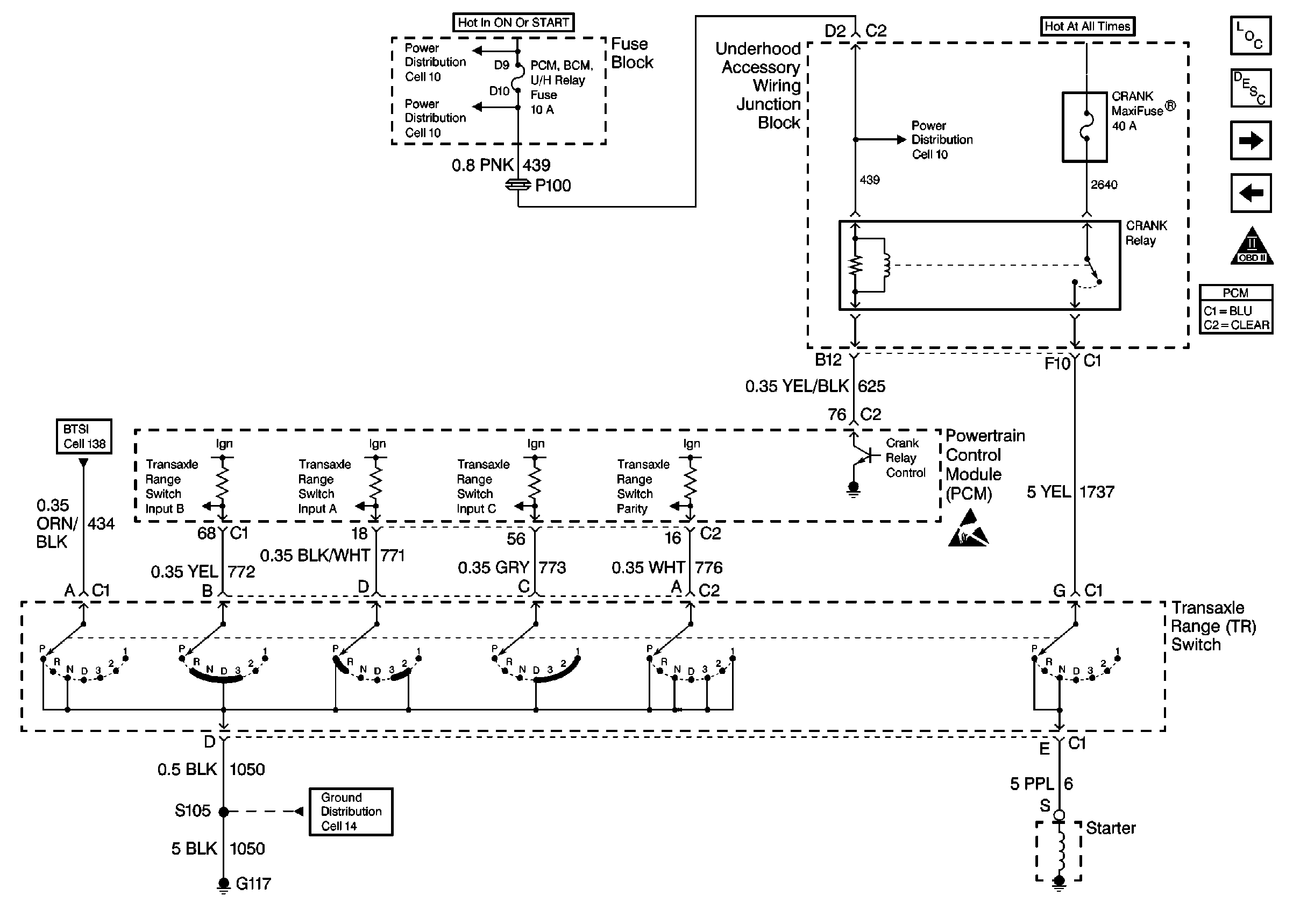
|
| Figure 11: |
Automatic Transaxle Internal Controls and TCC
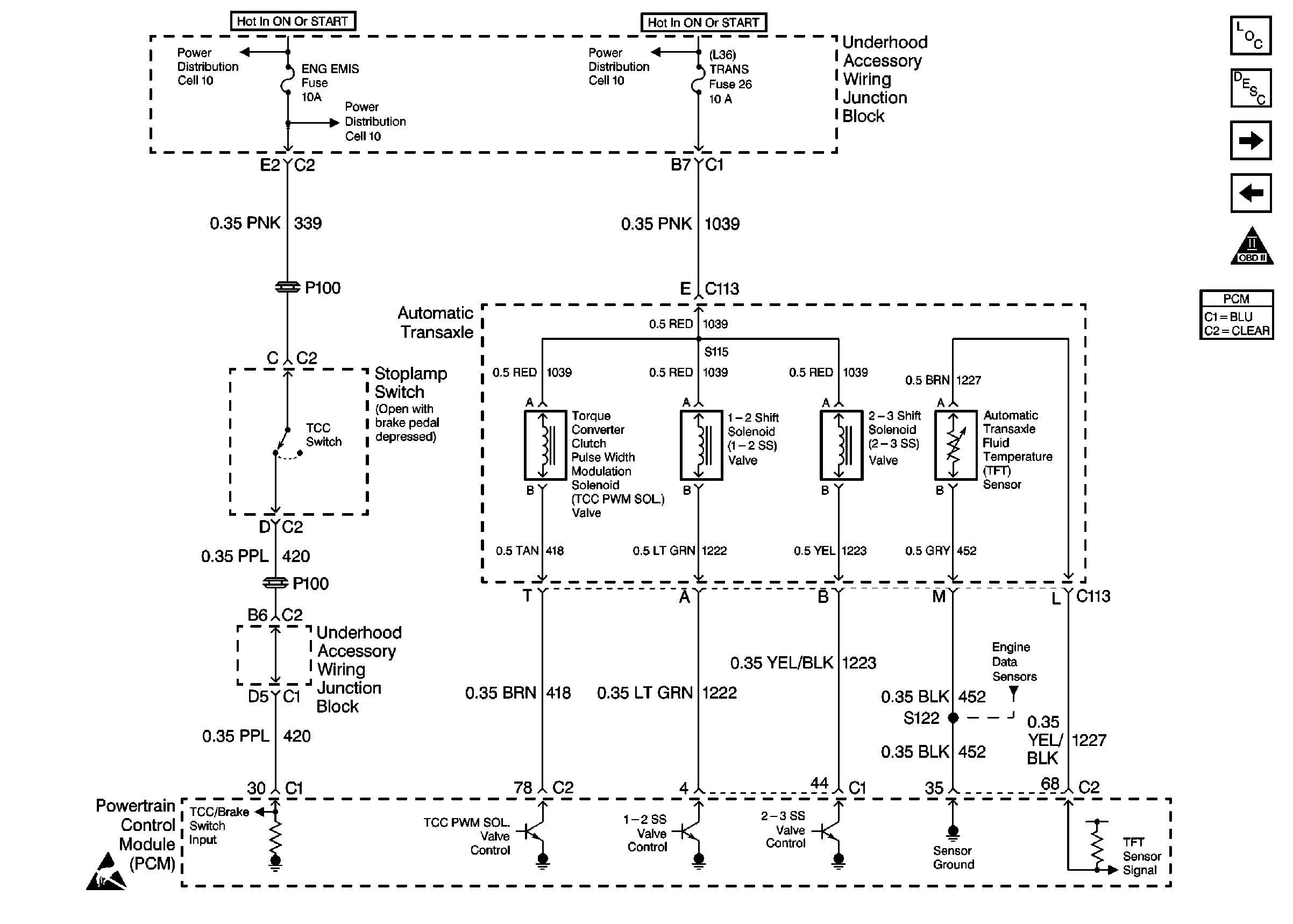
|
| Figure 12: |
A/T Fluid Pressure Manual Valve Position Switch, PC SOL
Valve and A/T ISS Sensor
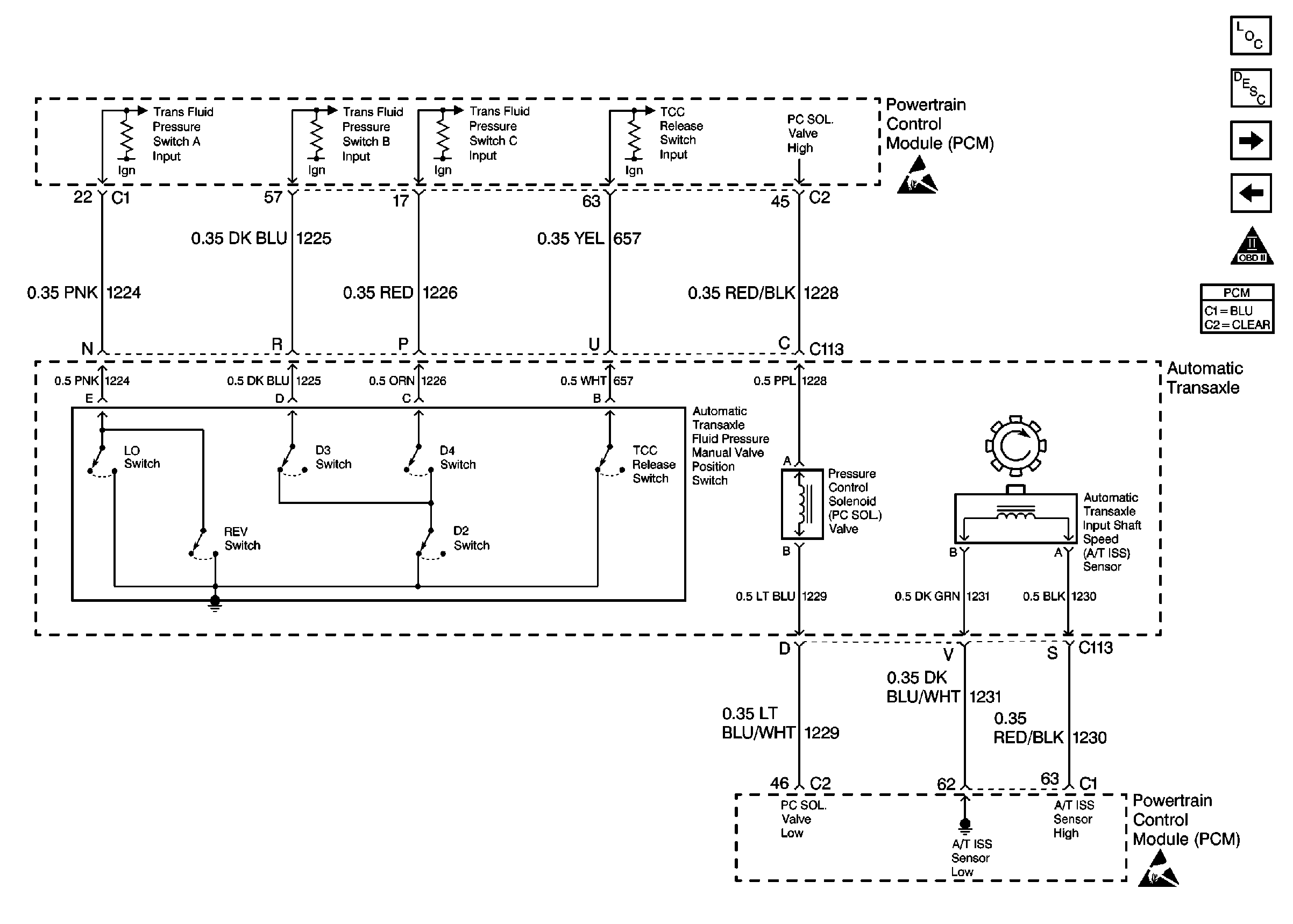
|
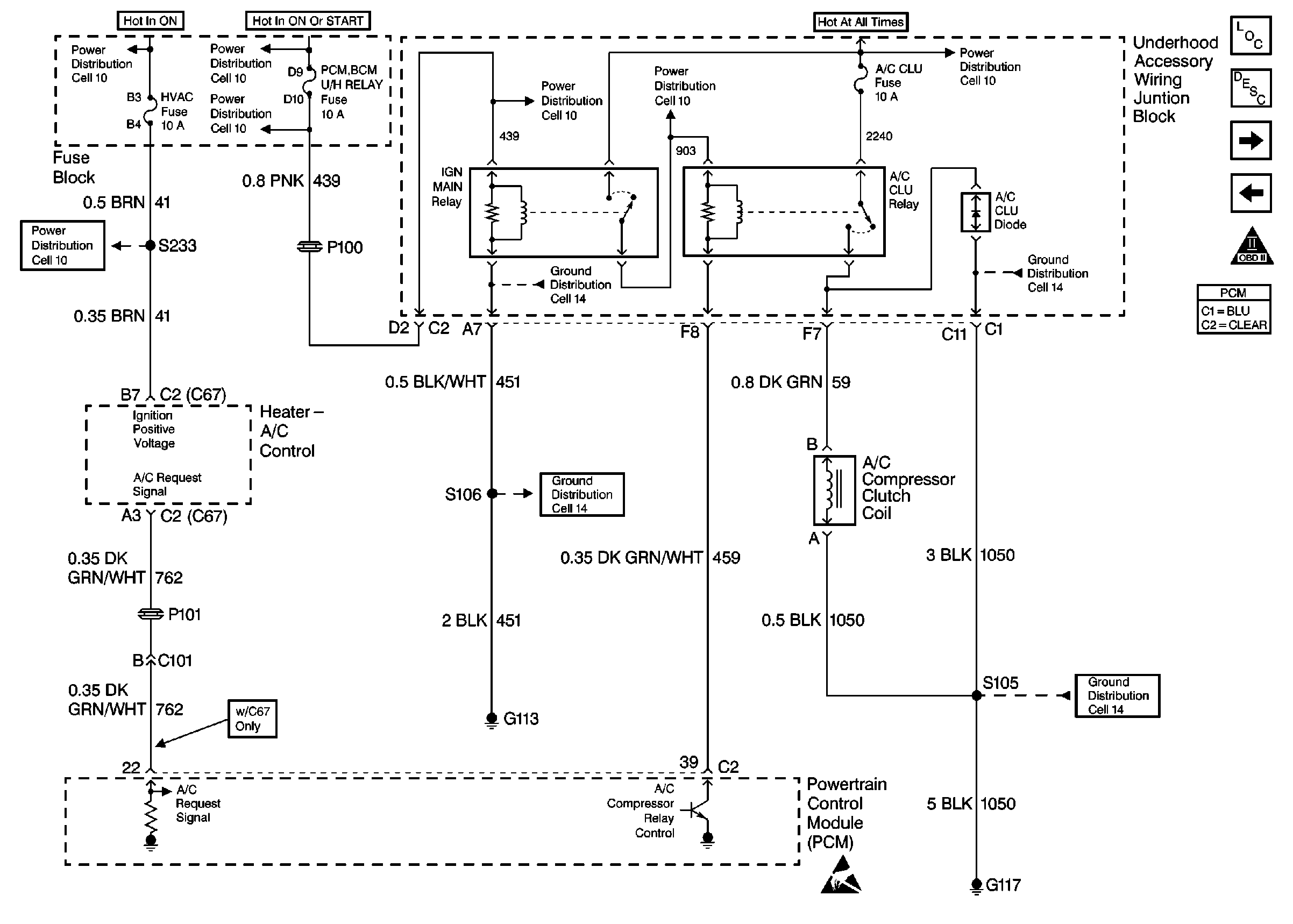
| Figure 13: |
A/C Compressor Controls
|
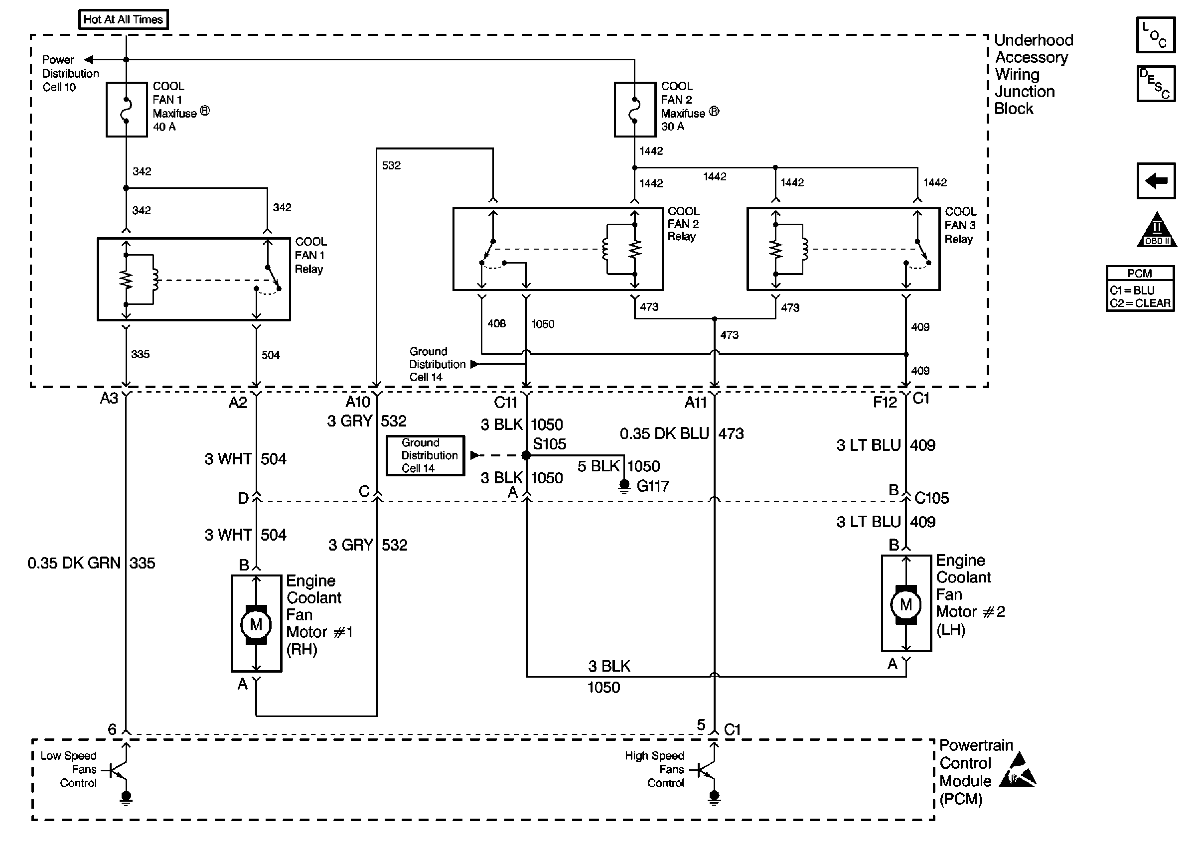
| Figure 14: |
Cooling Fans Controls
|
