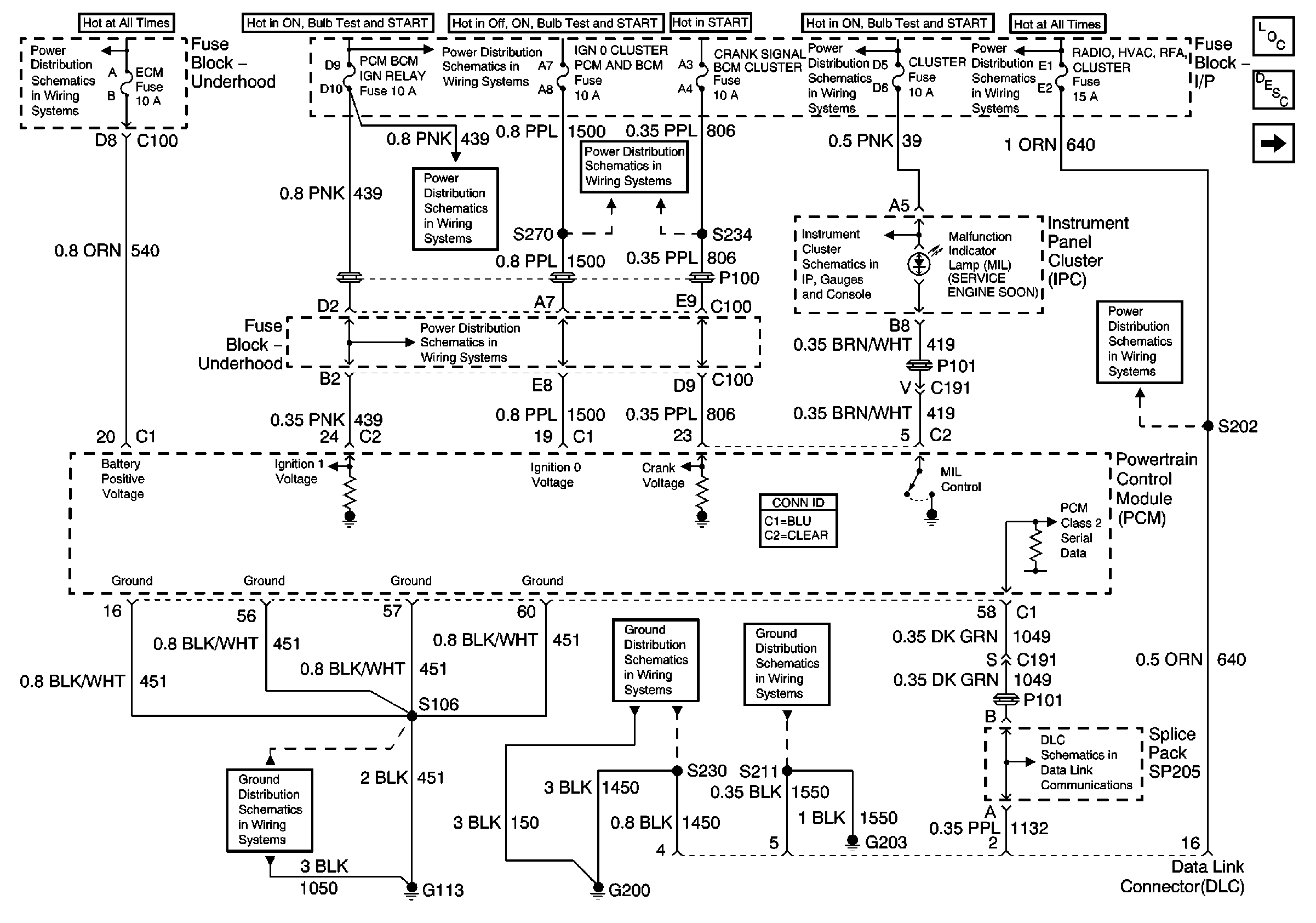
| Figure 1: |
Powers, Grounds and DLC
|
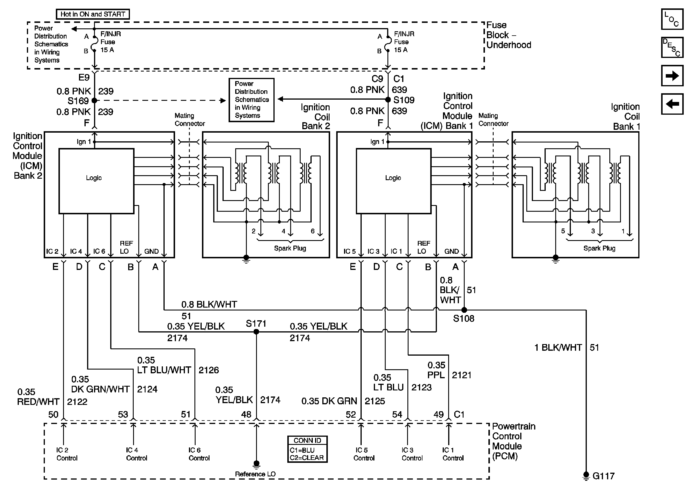
| Figure 2: |
Bank 1 and Bank 2 Ignition Control Modules
|
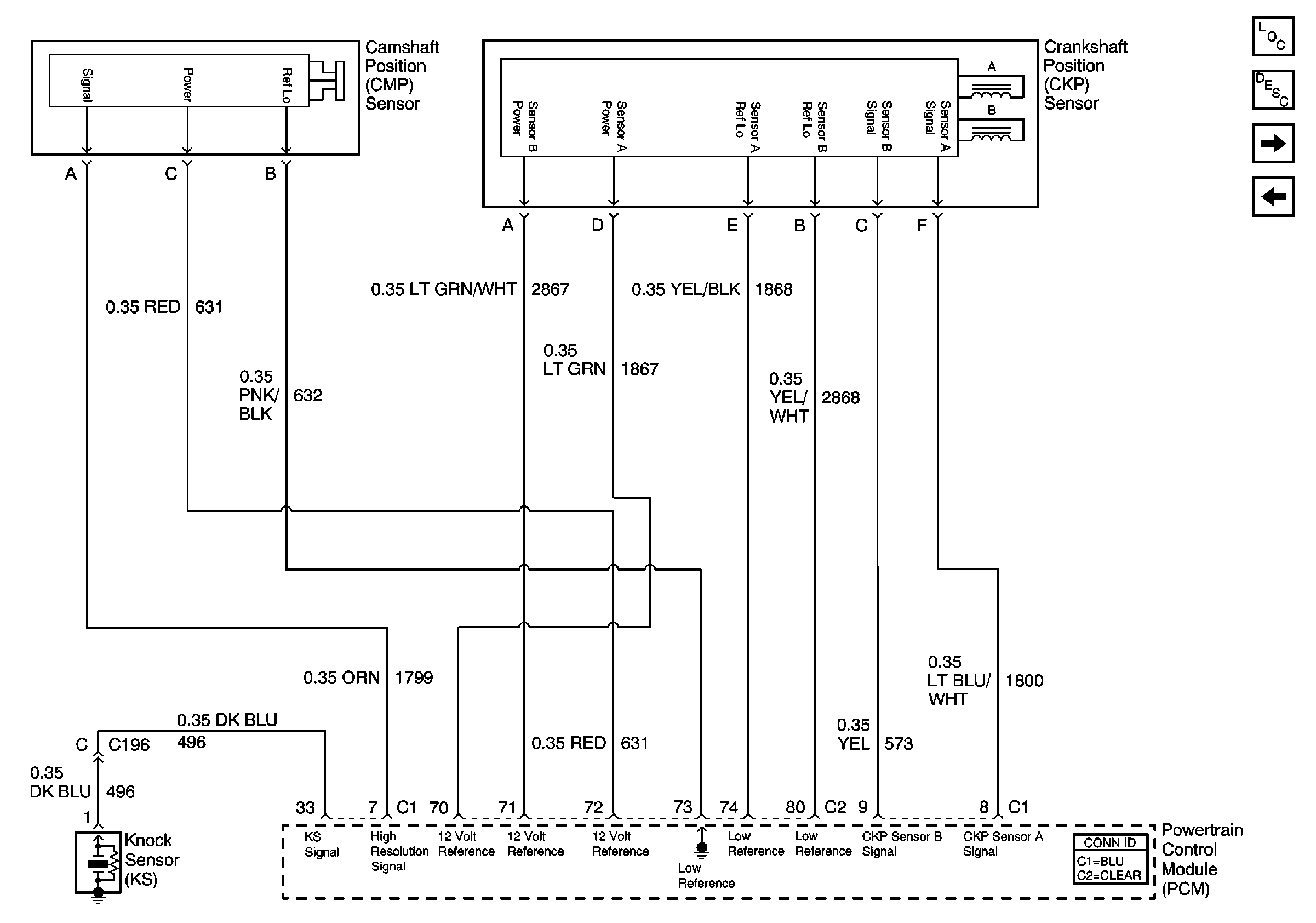
| Figure 3: |
Crankshaft and Camshaft Position Sensors
|
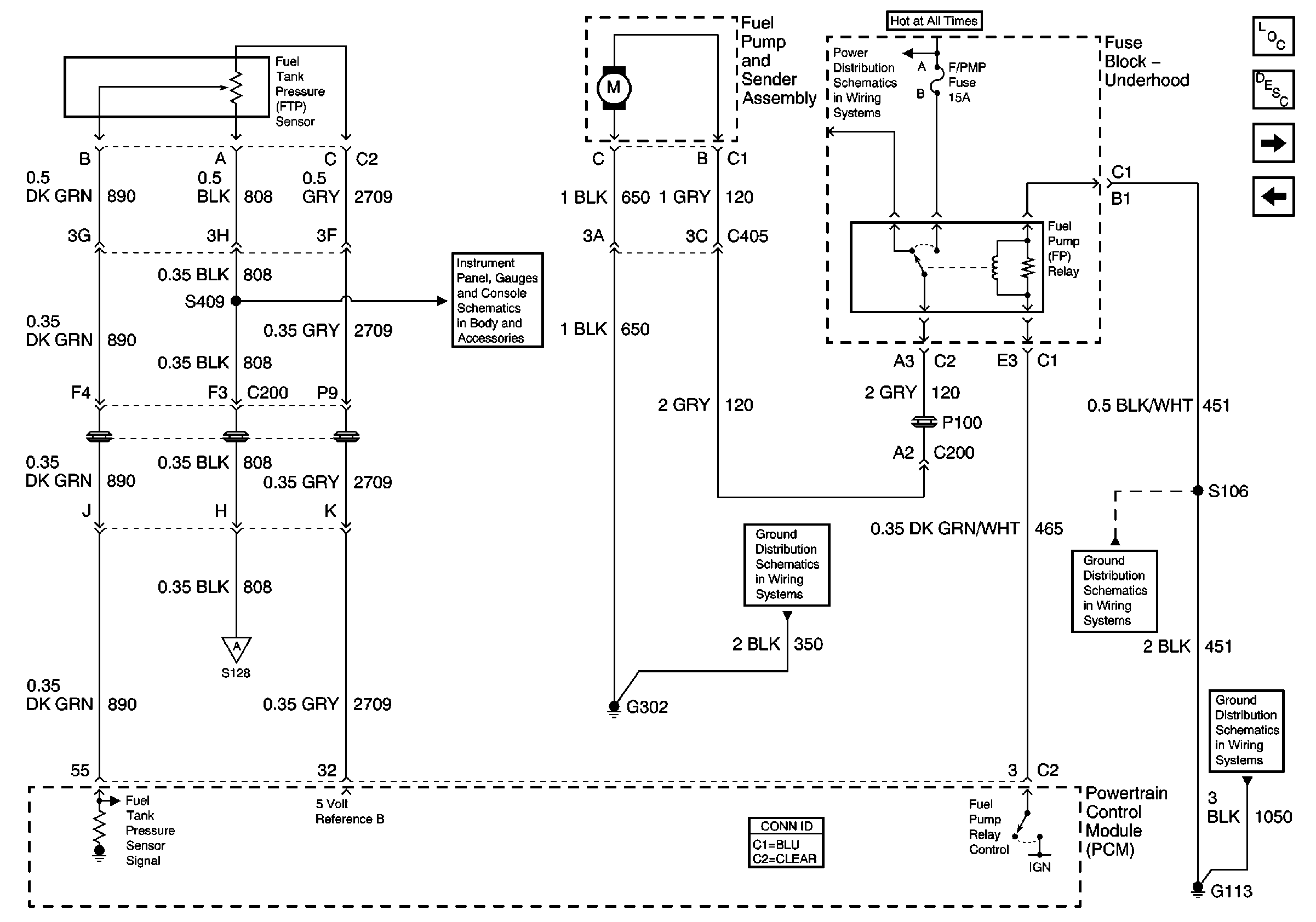
| Figure 4: |
Fuel System Inputs
|
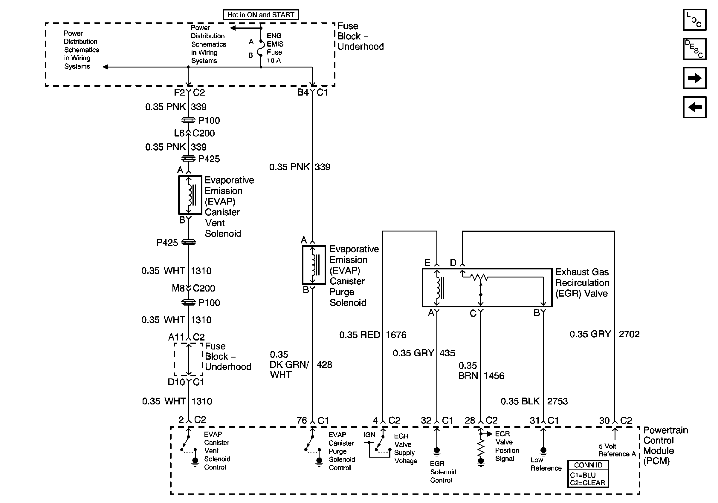
| Figure 5: |
Emission Inputs
|
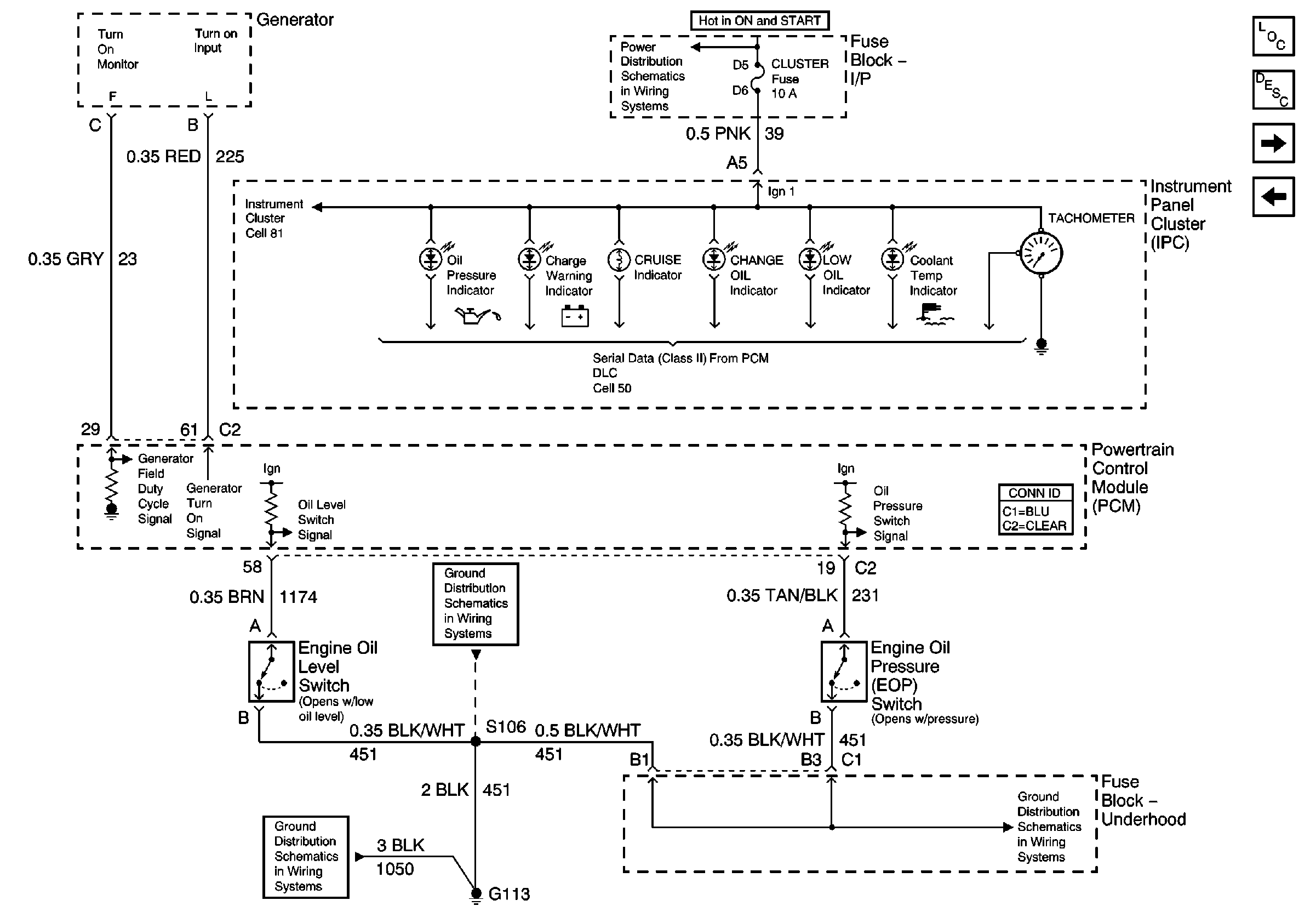
| Figure 6: |
Engine Oil Level and Pressure Inputs
|
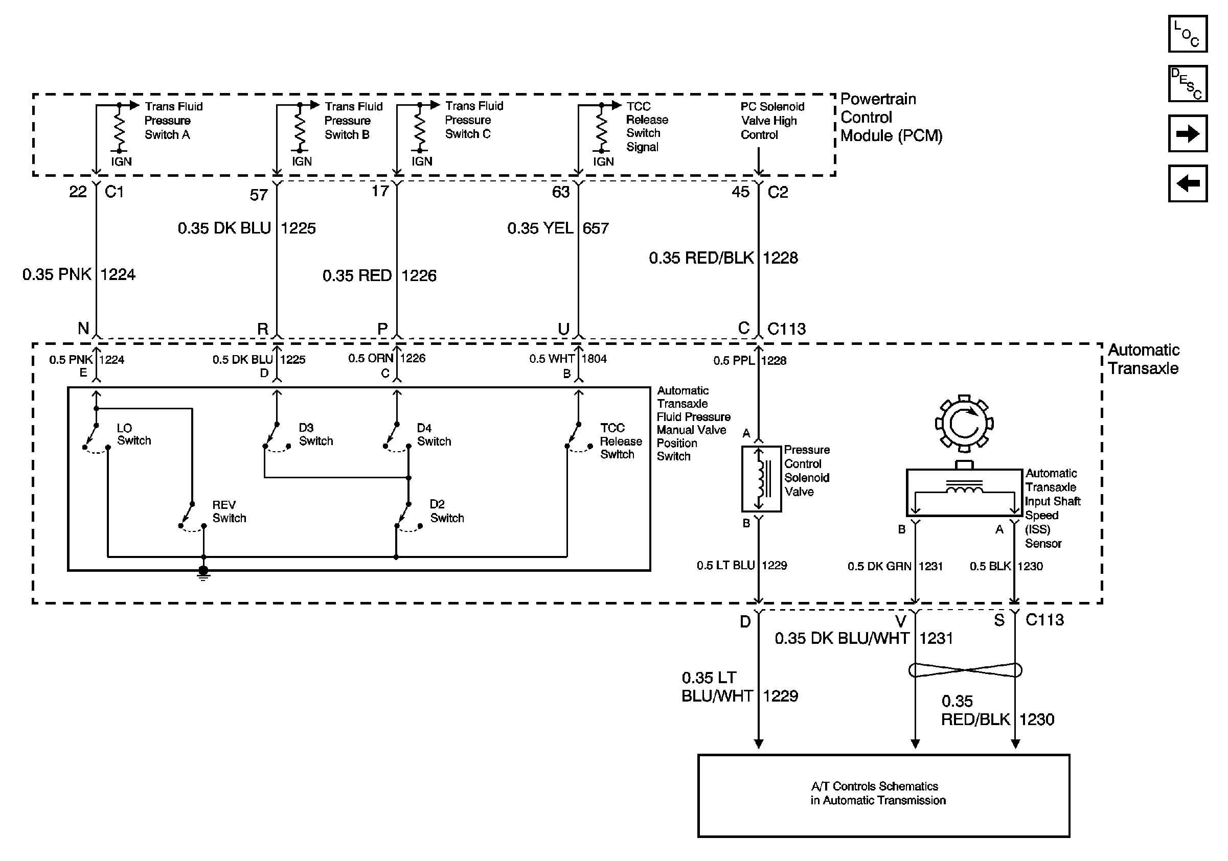
| Figure 7: |
Automatic Transaxle Inputs (1 of 2)
|
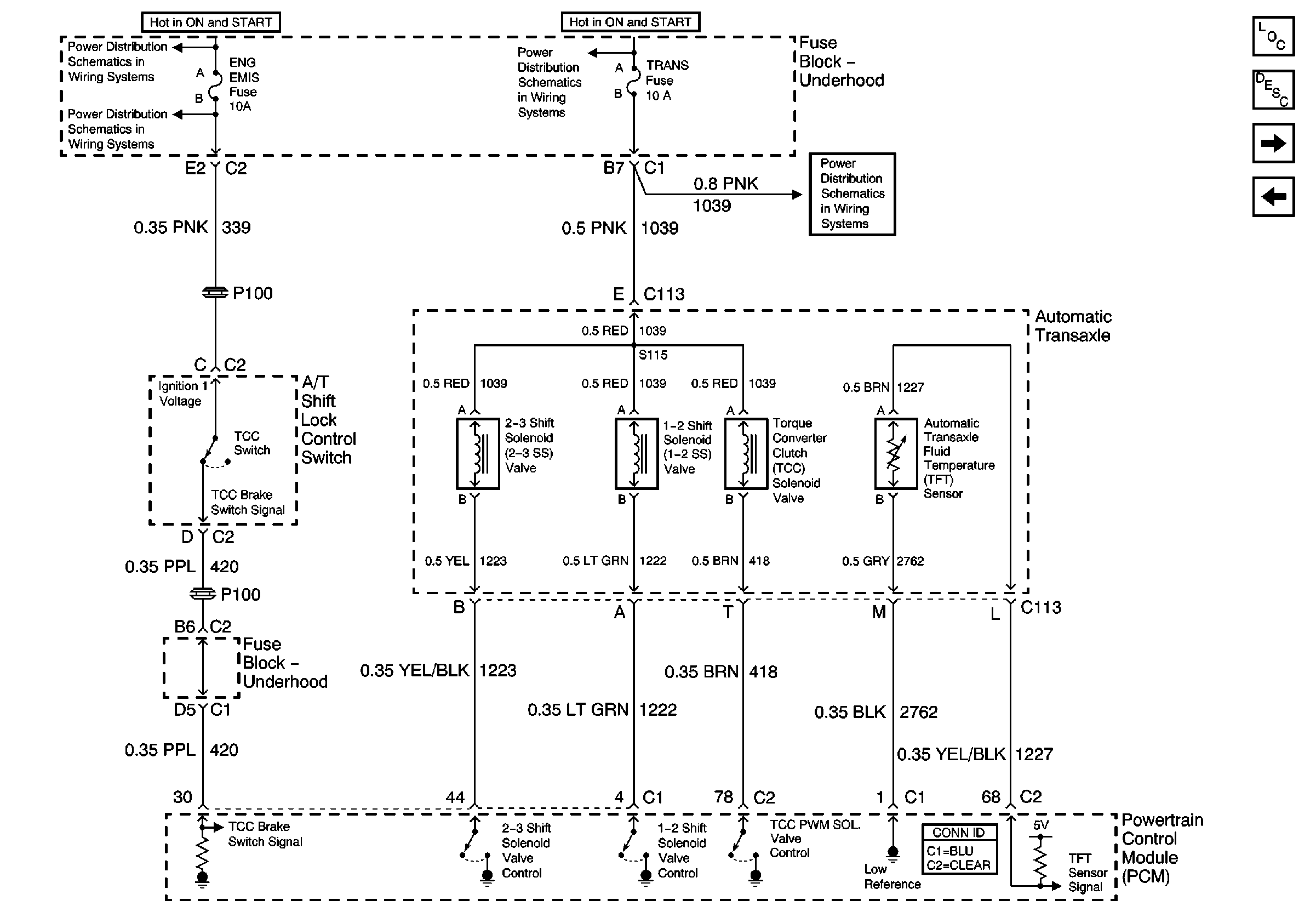
| Figure 8: |
Automatic Transaxle Inputs (2 of 2)
|
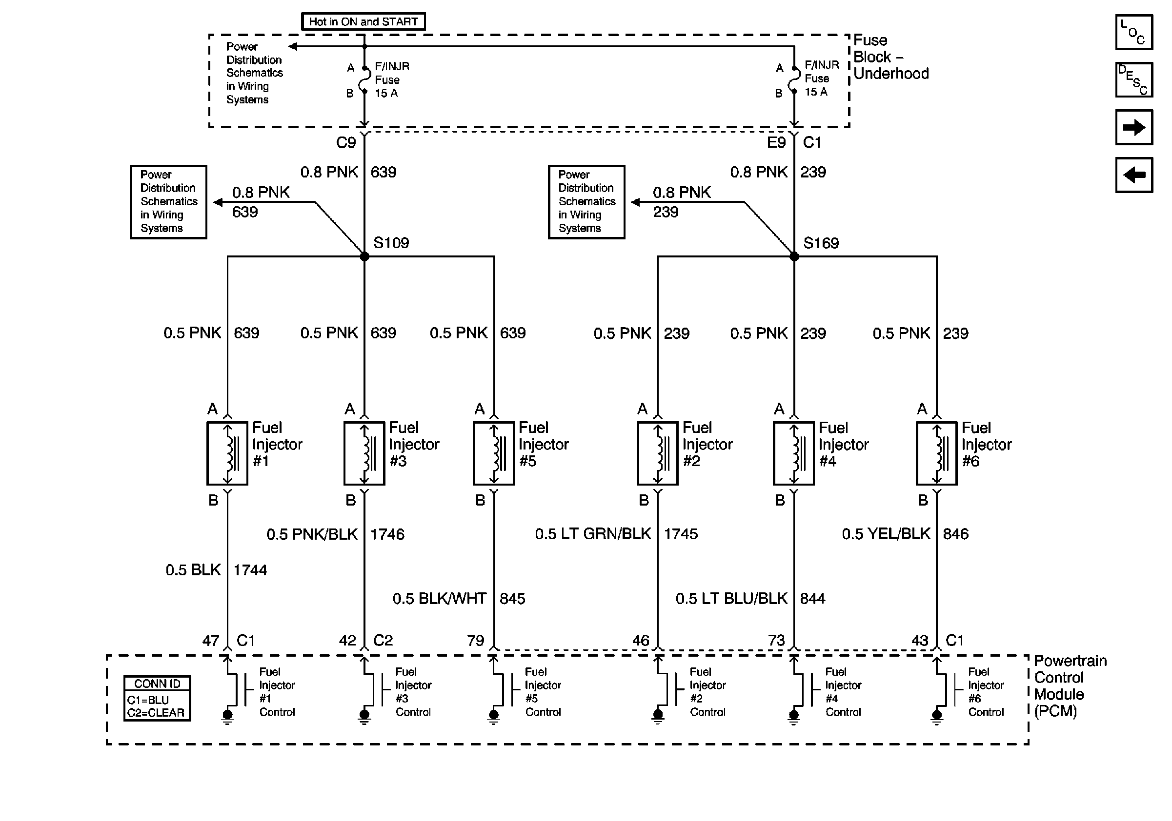
| Figure 9: |
Fuel Injectors
|
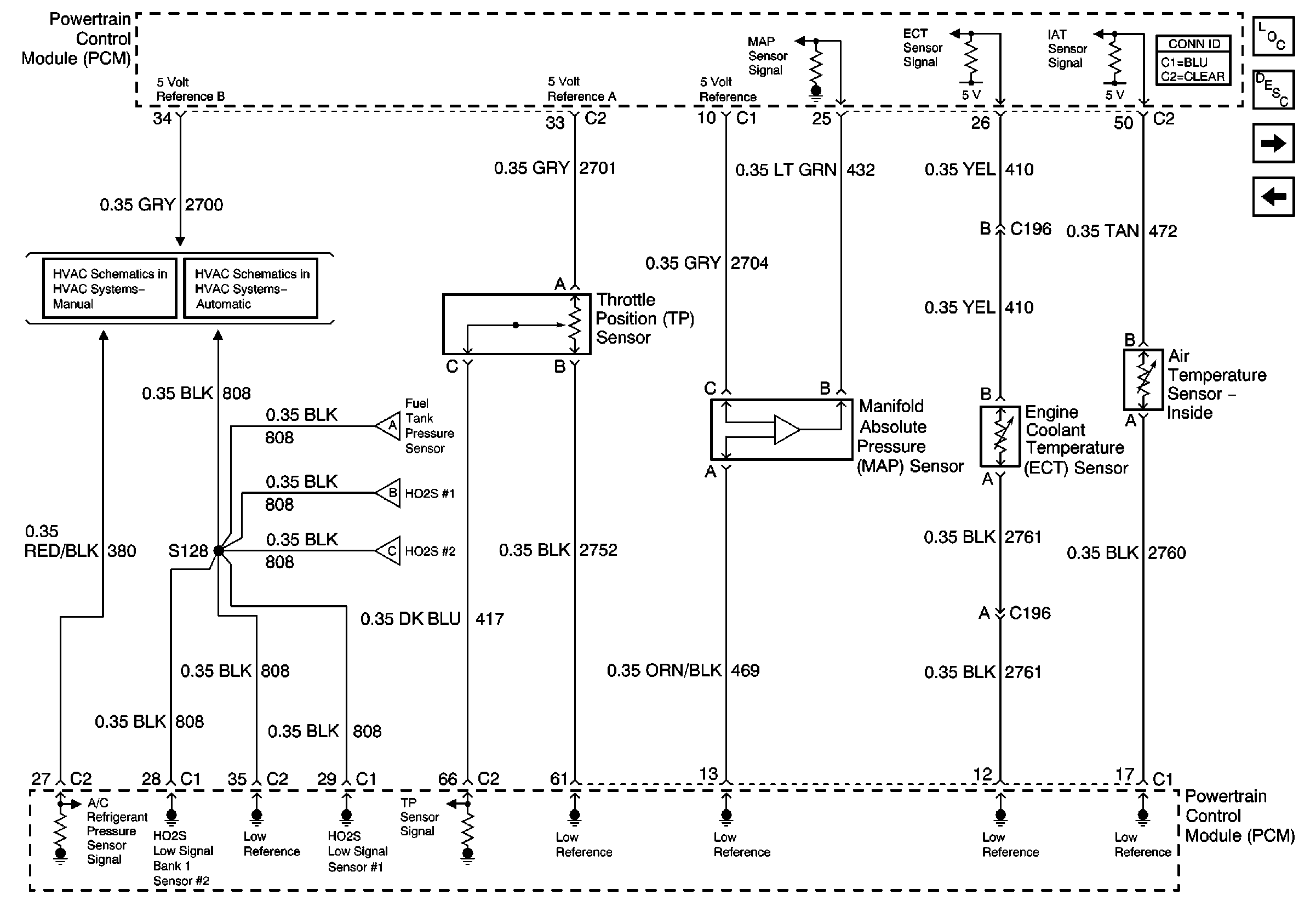
| Figure 10: |
A/C, TP, MAP, ECT and IAT Sensors
|
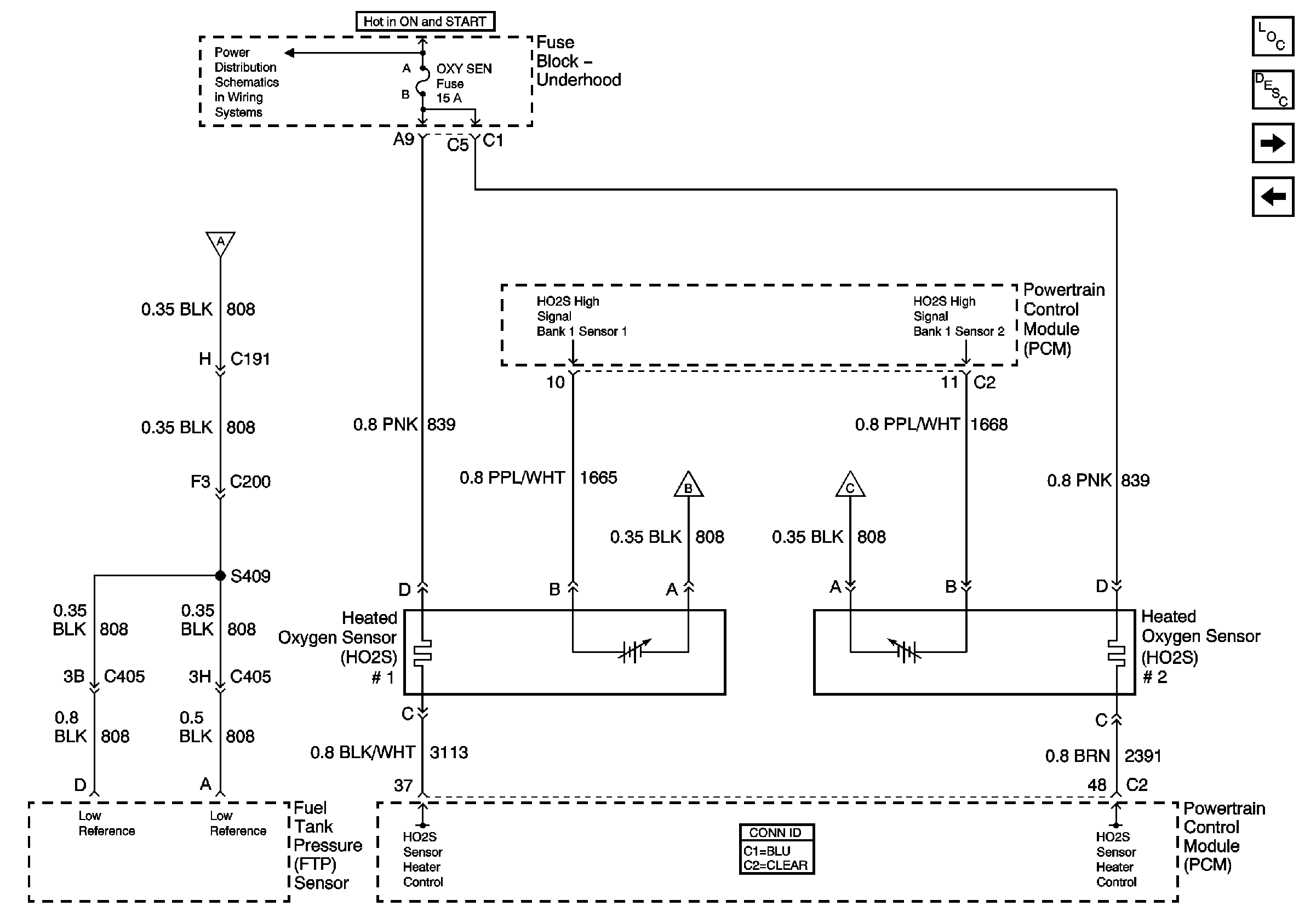
| Figure 11: |
Heated O2 Sensors
|
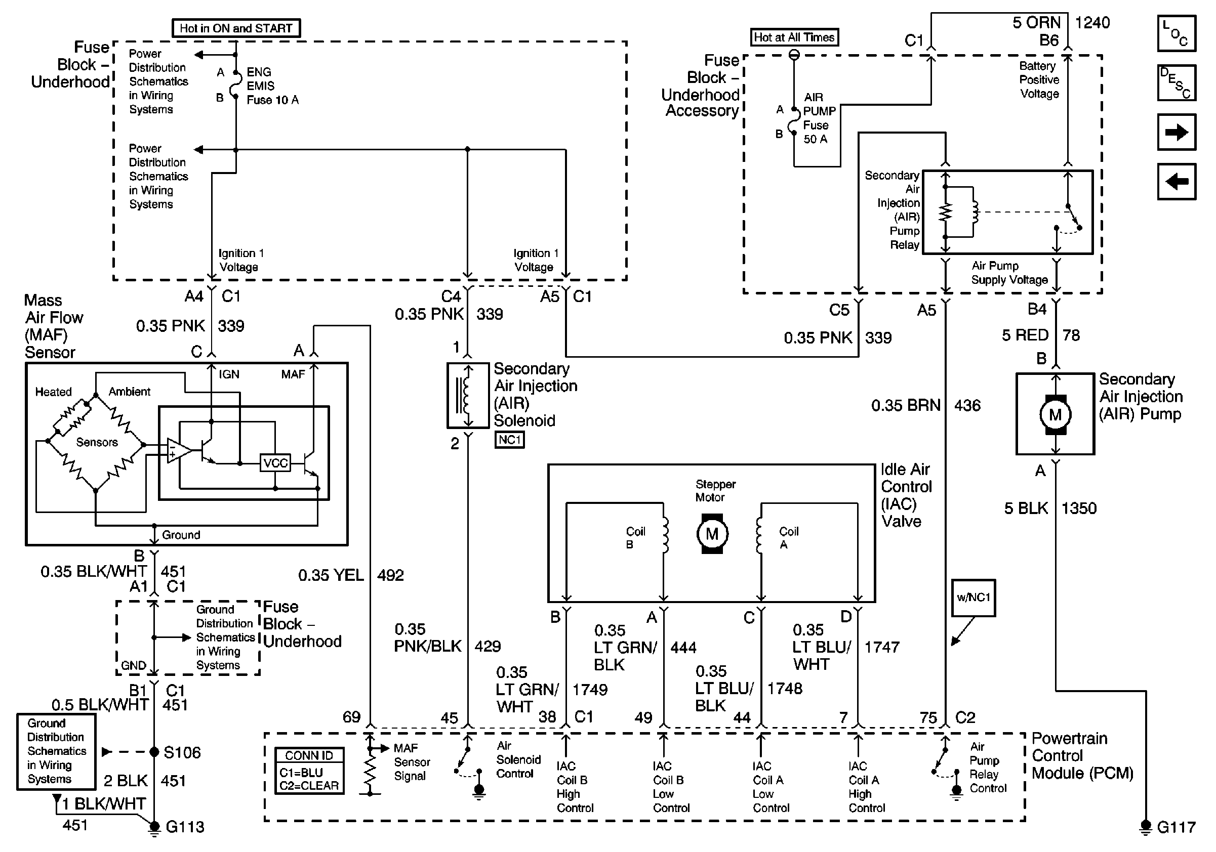
| Figure 12: |
Secondary AIR Bypass Valve Solenoid, AIR Pump, IAC Valve and MAF Sensor
|
| Figure 13: |
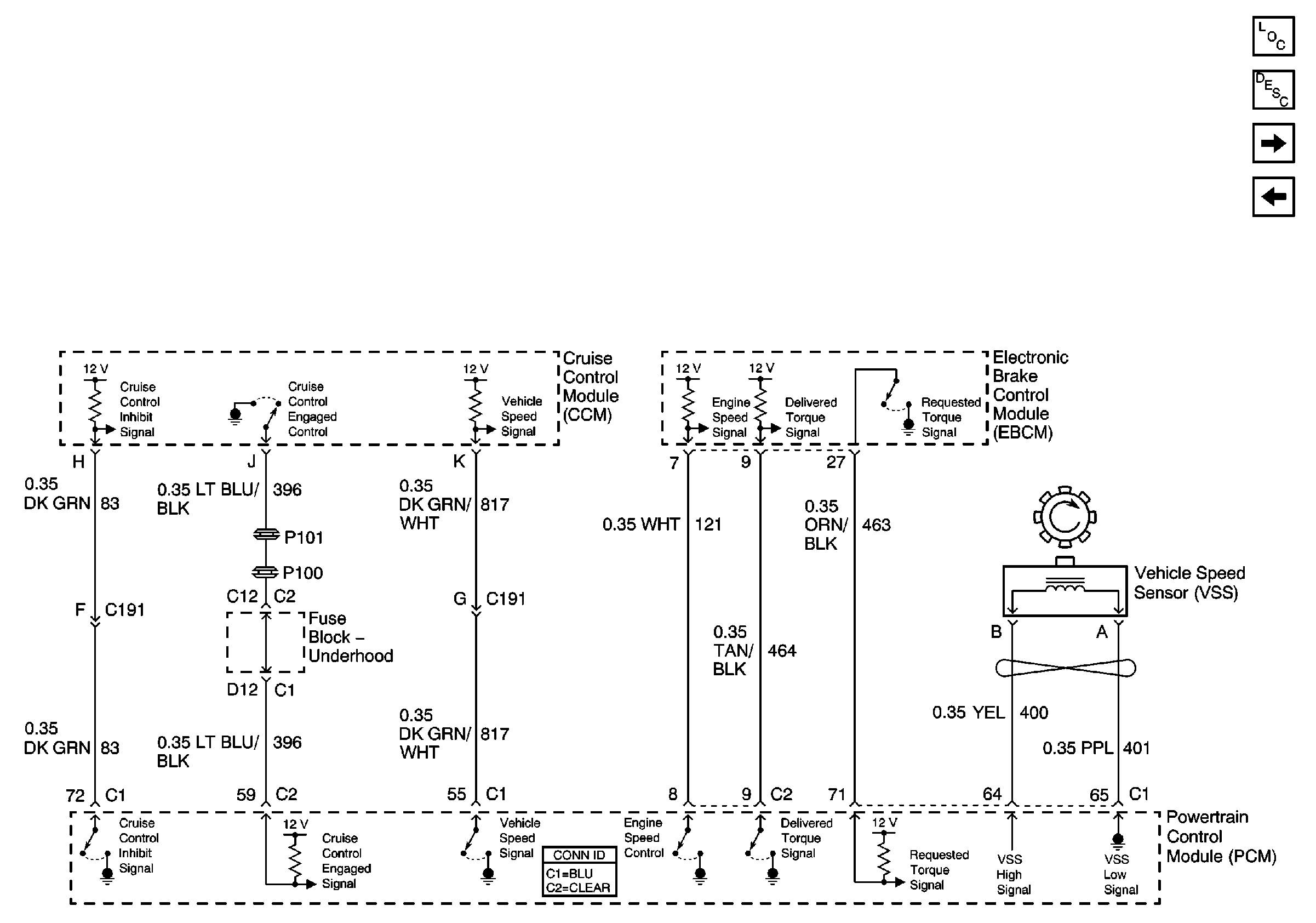
VSS, EBCM and Cruise Modules
|
| Figure 14: |
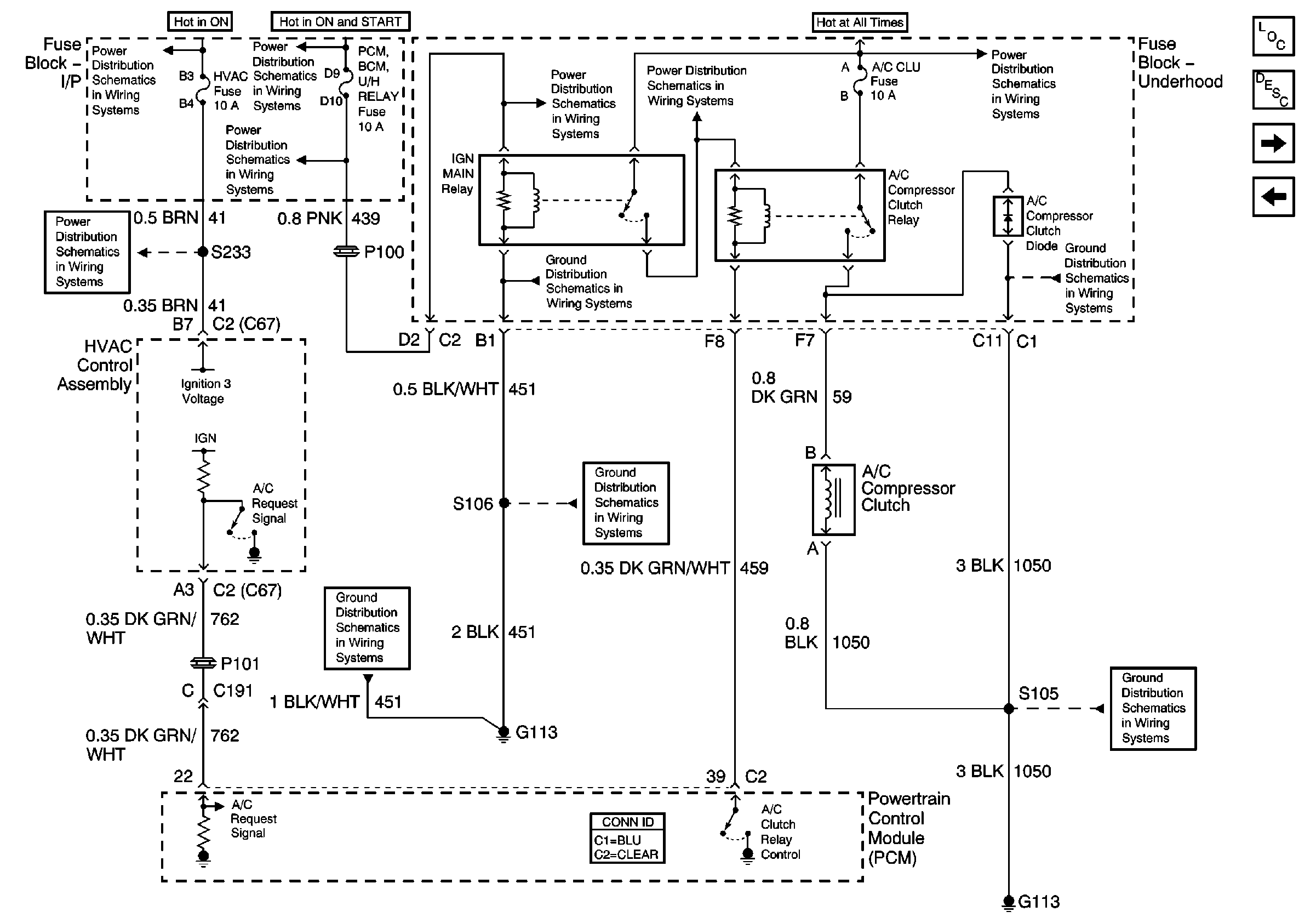
A/C Request and A/C Clutch Relay Control Signals
|
| Figure 15: |
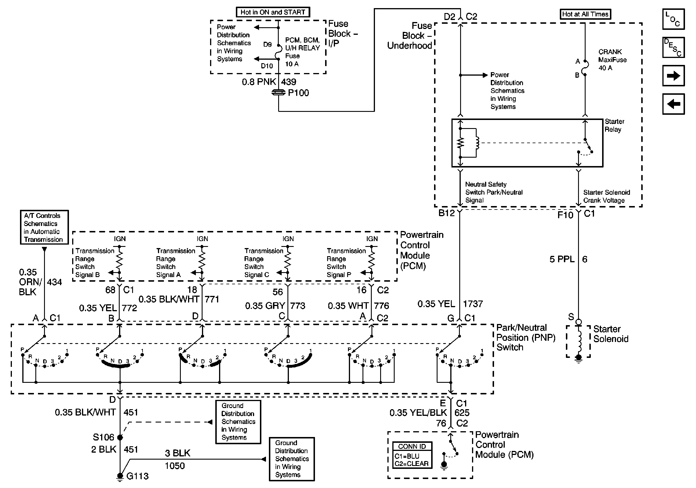
PNP Switch Outputs
|
| Figure 16: |
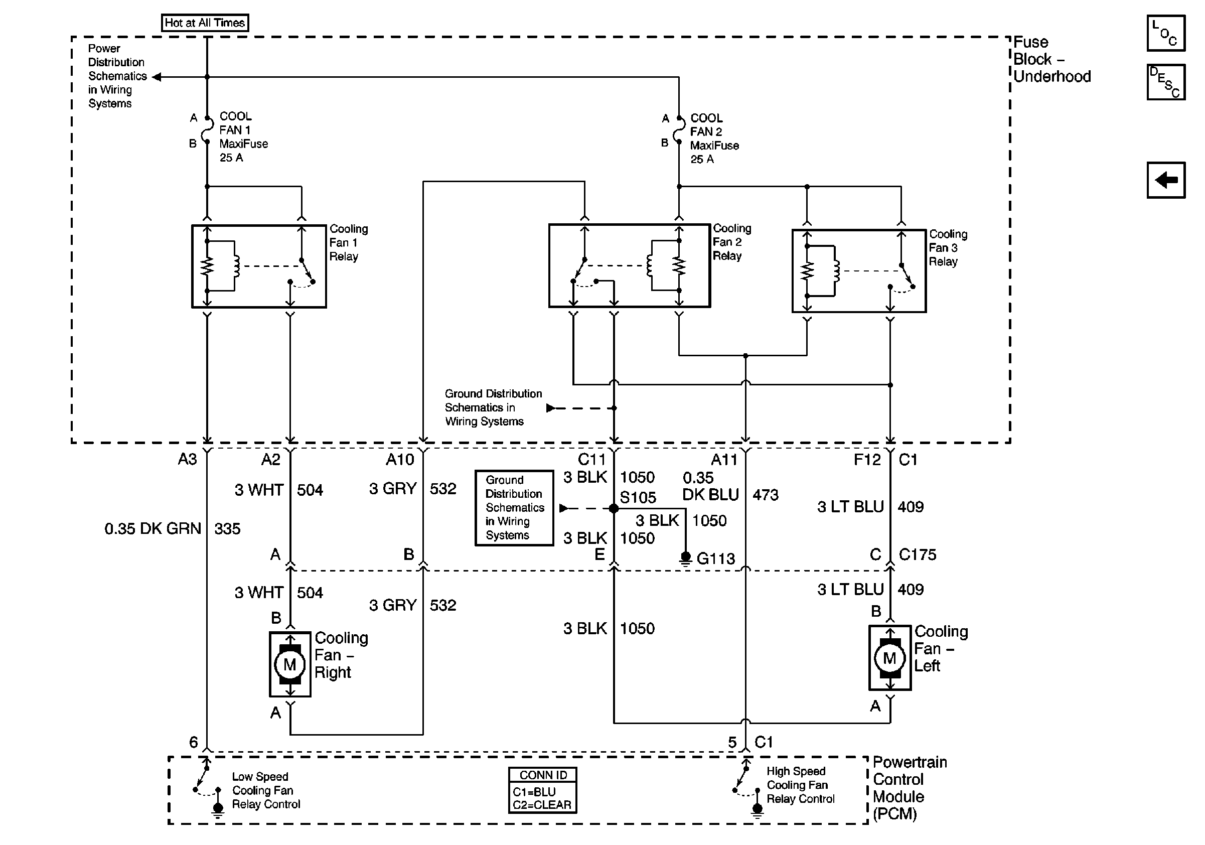
Engine Cooling Fans
|


