Rear Side Door Actuator Cable Tension Adjustment Regular Wheel Base
Adjustment Procedure
- Disconnect the negative battery cable. Refer to Battery Negative Cable Disconnection and Connection in Engine Electrical.
- Remove the right rear quarter lower trim panel. Refer to Rear Quarter Lower Trim Panel Replacement in Interior Trim.
- Position the center roller bracket at the front of the track. Ensure that the bracket is 25 mm (1 in) from the forward radius and that the cable tension slot is accessible in the window located on the PSD motor clutch assembly.
- Insert a 9 mm (3/8 in) drill bit into the tension slot on the actuator motor.
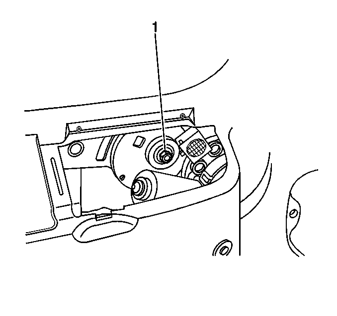
- Turn the 14 mm cable adjuster nut (1) counter-clockwise until the tensioner pins are located between both the front and rear double blocks. The blocks are marked on the PSD module housing. This action adjust the cable tension. If the adjuster nut rounds, refer to Rear Side Door Actuator Cable Tension Adjustment .
- Remove the 9 mm (3/8 in) drill bit from the cable tension slot.
- Operate the sliding door manually.
- Verify that the tension is correct.
- Connect the negative battery cable. Refer to Battery Negative Cable Disconnection and Connection in Engine Electrical.
- Perform the reinitialization procedure. Refer to Power Sliding Door (PSD) Re-Initialization .
- Place the jack in the storage compartment.
- Close the storage compartment door.
- Install the right rear quarter lower trim panel. Refer to Rear Quarter Lower Trim Panel Replacement in Interior Trim.
Caution: Unless directed otherwise, the ignition and start switch must be in the OFF or LOCK position, and all electrical loads must be OFF before servicing any electrical component. Disconnect the negative battery cable to prevent an electrical spark should a tool or equipment come in contact with an exposed electrical terminal. Failure to follow these precautions may result in personal injury and/or damage to the vehicle or its components.

Important: Use only a 6-point 14 mm socket on the adjusting nut. The adjusting nut requires very little torque to achieve proper cable tension. Do not exceed 20 N·m of torque on the adjuster nut. Use of additional torque beyond 20 N·m may damage the adjuster nut. If the adjuster nut rounds, refer to Rear Side Door Actuator Cable Tension Adjustment .
Rear Side Door Actuator Cable Tension Adjustment Extended Wheel Base
Adjustment Procedure
- Remove the left or right rear quarter lower trim panel. Refer to Rear Quarter Lower Trim Panel Replacement in Interior Trim.
- Disconnect the negative battery cable. Refer to Battery Negative Cable Disconnection and Connection in Engine Electrical.
- Position the sliding door center roller bracket at the front of the track. Ensure that the bracket is 25 mm (1 in) from the point where the cable tension adjuster nut is accessible in the adjuster window located on the motor clutch assembly.
- Turn the 15 mm cable adjuster nut counter-clockwise until the tensioner pins are located between both the front and rear double blocks. The blocks are marked on the PSD module housing in order to adjust the cable tension. If the adjuster nut rounds, refer to Rear Side Door Actuator Cable Tension Adjustment .
Caution: Unless directed otherwise, the ignition and start switch must be in the OFF or LOCK position, and all electrical loads must be OFF before servicing any electrical component. Disconnect the negative battery cable to prevent an electrical spark should a tool or equipment come in contact with an exposed electrical terminal. Failure to follow these precautions may result in personal injury and/or damage to the vehicle or its components.
Important: Use only a 6-point 14 mm socket on the adjusting nut. The adjusting nut requires very little torque to achieve proper cable tension. Do not exceed 20 N·m of torque on the adjuster nut. Use of additional torque beyond 20 N·m may damage the adjuster nut. If the adjuster nut rounds, refer to Rear Side Door Actuator Cable Tension Adjustment .
Installation Procedure
- Connect the negative battery cable. Refer to Battery Negative Cable Disconnection and Connection in Engine Electrical.
- Perform the reinitialization procedure. Refer to Power Sliding Door (PSD) Re-Initialization .
- Install the left or right rear quarter lower trim panel. Refer to Rear Quarter Lower Trim Panel Replacement in Interior Trim.
Rear Side Door Actuator Cable Tension Adjustment Regular - Alternate
Adjustment Procedure
- Remove the right rear quarter lower trim panel. Refer to Rear Quarter Lower Trim Panel Replacement in Interior Trim.
- Disconnect the negative battery cable. Refer to Battery Negative Cable Disconnection and Connection in Engine Electrical.
- Position the sliding door center roller bracket at the front of the track. Ensure that the bracket is 25 mm (1 in) away from the forward radius and that the cable tension adjuster nut is accessible in the adjuster window located on the PSD motor clutch assembly.
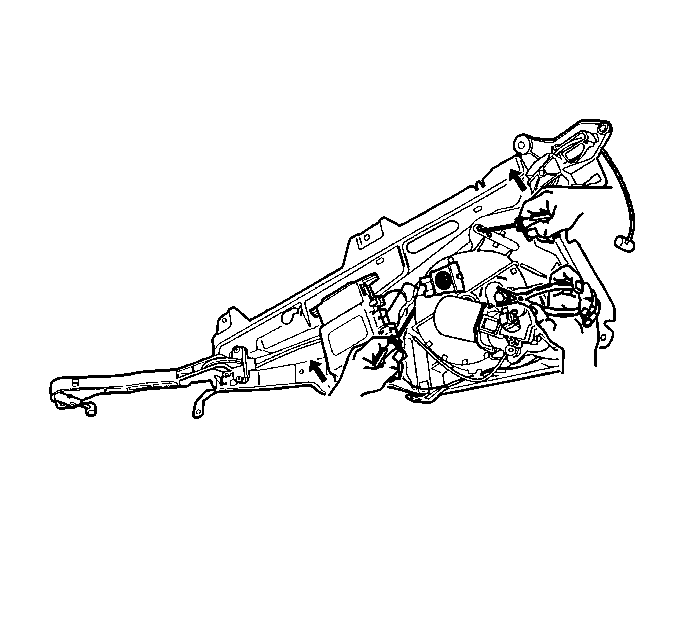
- Use two medium Phillips head screwdrivers in order to move the cable tension indicators to the uppermost portion of the tension indicating windows. Hold the tension indicators in place in order to reduce the amount of force that is required to turn the adjuster nut.
- Insert the chuck end of a 9 mm (3/8 in) drill bit into the tensioning slot in the actuator motor.
- Complete the following steps simultaneously until you feel resistance in the cable. Resistance indicates that the cable is taut:
- Release the inward pressure on the nut and allow the nut to lock into place.
- Release the cable tension indicators.
- Verify that the cable tension indicators are located between both the front and rear double blocks marked on the PSD module housing. The tension is acceptable if the indicators are slightly high but are touching the indicator marks. If the indicators are below the indicator marks, repeat step 6 through step 11 until you obtain enough tension. If the tension is too high, push in on the adjuster nut in order to release the tension, then repeat step 6 through step 11.
- Operate the sliding door manually.
- Position the door as described in step 5. Verify that the tension is correct. If the tension is incorrect , repeat step 6 through step 11 until you obtain the correct tension.
- Install the right rear quarter lower trim panel. Refer to Rear Quarter Lower Trim Panel Replacement in Interior Trim.
- Connect the negative battery cable. Refer to Battery Negative Cable Disconnection and Connection in Engine Electrical.
- Perform the reinitialization procedure. Refer to Power Sliding Door (PSD) Re-Initialization .
Caution: Unless directed otherwise, the ignition and start switch must be in the OFF or LOCK position, and all electrical loads must be OFF before servicing any electrical component. Disconnect the negative battery cable to prevent an electrical spark should a tool or equipment come in contact with an exposed electrical terminal. Failure to follow these precautions may result in personal injury and/or damage to the vehicle or its components.

| • | Grasp the tension adjusting nut with pliers. |
| • | Push the nut inward. |
| • | Turn the nut counter-clockwise. |
Rear Side Door Actuator Cable Tension Adjustment Extended - Alternate
Adjustment Procedure
- Remove the right rear quarter lower trim panel. Refer to Rear Quarter Lower Trim Panel Replacement in Interior Trim.
- Disconnect the negative battery cable. Refer to Battery Negative Cable Disconnection and Connection in Engine Electrical.
- Position the sliding door center roller bracket at the front of the track. Ensure that the bracket is 25 mm (1 in) from the forward radius and that the cable tension slot is accessible in the window located on the PSD motor clutch assembly.
- Use two medium Phillips head screwdrivers in order to move the cable tension indicators to the uppermost portion of the tension indicating windows. Hold the tension indicators in place in order to reduce the amount of force that is required in order to turn the adjuster nut.
- Complete the following steps simultaneously until you feel resistance in the cable. Resistance indicates that the cable is taut:
- Release the outward pressure on the nut and allow the nut to lock into place.
- Release the cable tension indicators.
- Verify that the cable tension indicators are located between both the front and rear double blocks. The blocks are marked on the PSD module housing. The tension is acceptable if the indicators are slightly high but are touching the indicator marks. If the indicators are below the indicator marks, Repeat Step 6 through Step 11 until you obtain enough tension. If the tension is too high, push in on the adjuster nut in order to release the tension, then repeat Step 6 through Step 11.
- Operate the sliding door manually.
- Position the door as described in Step 5. Verify that the tension is correct. If the tension is incorrect, repeat Step 6 through Step 11 until you obtain correct tension.
- Install the right rear quarter lower trim panel. Refer to Rear Quarter Lower Trim Panel Replacement in Interior Trim.
- Connect the negative battery cable. Refer to Battery Negative Cable Disconnection and Connection in Engine Electrical.
- Perform the reinitialization procedure. Refer to Power Sliding Door (PSD) Re-Initialization .
Caution: Unless directed otherwise, the ignition and start switch must be in the OFF or LOCK position, and all electrical loads must be OFF before servicing any electrical component. Disconnect the negative battery cable to prevent an electrical spark should a tool or equipment come in contact with an exposed electrical terminal. Failure to follow these precautions may result in personal injury and/or damage to the vehicle or its components.

| • | Grasp the tension adjusting nut with pliers. |
| • | Pull the nut outward. |
| • | Turn the nut counter-clockwise. |
