| Table 1: | C101 |
| Table 2: | C102 (LA1) |
| Table 3: | C103 |
| Table 4: | C105 |
| Table 5: | C106 (LY7) |
| Table 6: | C108 (LY7) |
| Table 7: | C120 - Pontiac/UH9 |
| Table 8: | C121 - Buick |
| Table 9: | C151 - Pontiac |
| Table 10: | C152 - Pontiac |
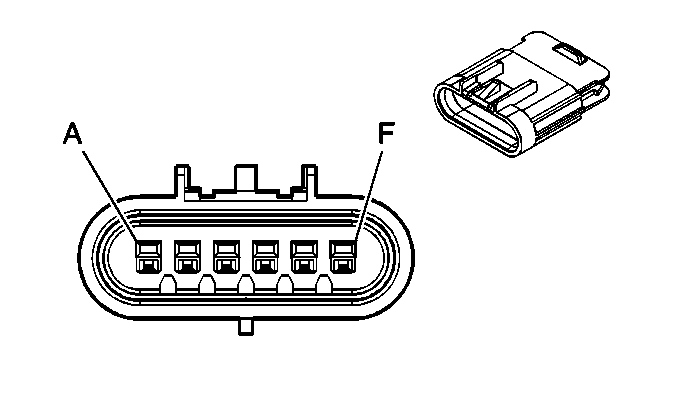
| Table 11: | C153 - Pontiac |
| Table 12: | C154 - Pontiac |
| Table 13: | C155 - Buick |
| Table 14: | C156 - Buick |
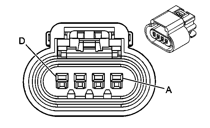
| Table 15: | C200 |
| Table 16: | C201 |
| Table 17: | C203 |
| Table 18: | C204 (Pontiac) |
| Table 19: | C206 (Buick) |
| Table 20: | C207 |
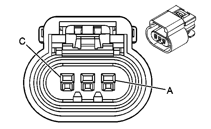
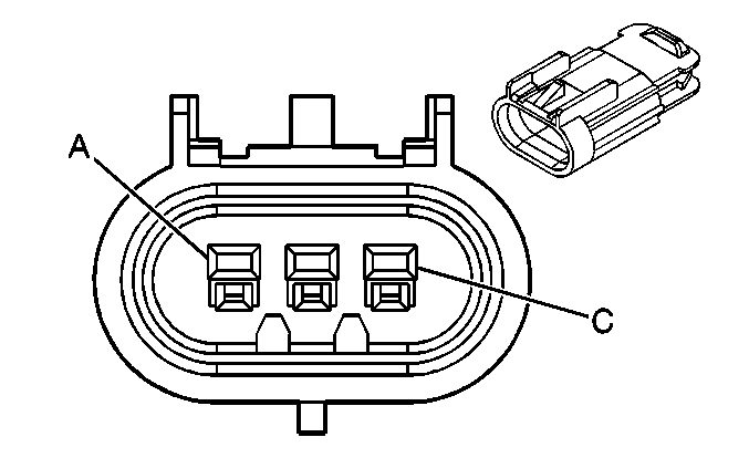
| Table 21: | C301 |
| Table 22: | C302 |
| Table 23: | C303 |
| Table 24: | C304 (G67) |
| Table 25: | C305 |
| Table 26: | C306 (JM4/JL9) |
| Table 27: | C308 (Pontiac) |
| Table 28: | C309 (JM4/JL9) |
| Table 29: | C310 (U32) |
| Table 30: | C310 (w/o U32) |
| Table 31: | C314 (AJ7 and AG2) |
| Table 32: | C314 (AG2 w/o AJ7) |
| Table 33: | C315 (KA1) |
| Table 34: | C316 (KA1) |
| Table 35: | C317 (A43) |
| Table 36: | C319 (KA1) |
| Table 37: | C320 (KA1) |
| Table 38: | C351 |
| Table 39: | C352 |
| Table 40: | C397 (CF5) |
| Table 41: | C403 Pontiac |
| Table 42: | C405 (G67) |
| Table 43: | C407 |
| Table 44: | C408 |
| Table 45: | C411 (UD7) |
| Table 46: | C413 (Buick) |
| Table 47: | C420 (V92) |
| Table 48: | C900 |
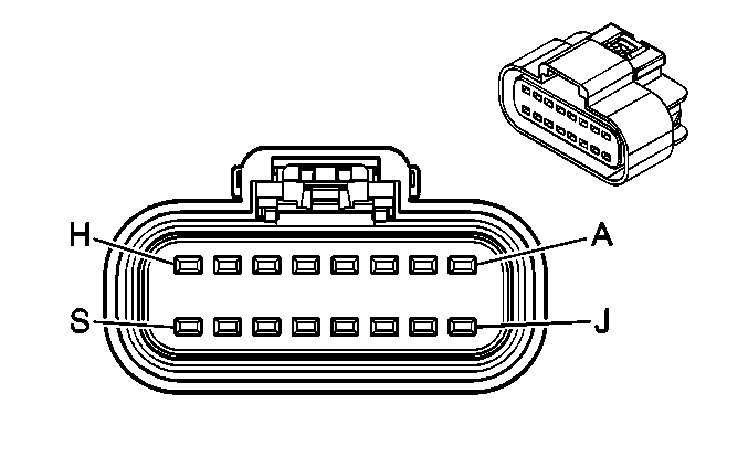
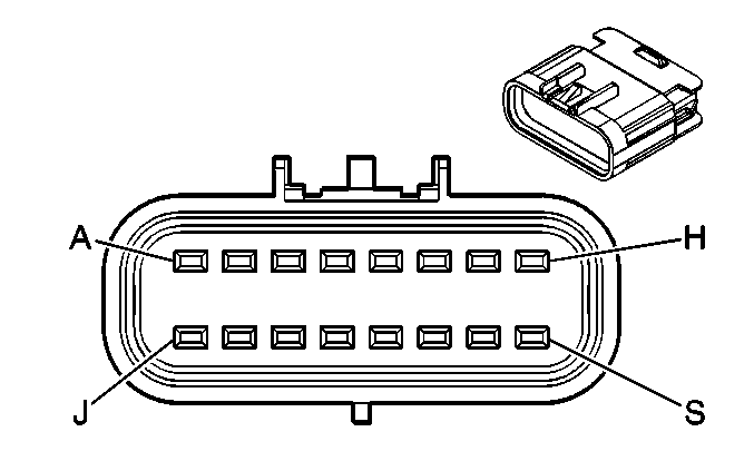
|
| ||||||||||||||
|---|---|---|---|---|---|---|---|---|---|---|---|---|---|---|---|
Connector Part Information |
| Connector Part Information |
| ||||||||||||
Pin | Wire Color | Circuit No. | Function | Pin | Wire Color | Circuit No. | Function | ||||||||
A | WH | 17 | Stop Lamp Switch Signal | A | WH | 17 | Stop Lamp Switch Signal | ||||||||
B | -- | -- | Not Used | B | -- | -- | Not Used | ||||||||
C | PK | 39 | Ignition 1 Voltage (LY7) | C | PK | 39 | Ignition 1 Voltage (LY7) | ||||||||
D | BN | 882 | Right Rear Wheel Speed Sensor Signal | D | BN | 882 | Right Rear Wheel Speed Sensor Signal | ||||||||
E | WH | 883 | Right Rear Wheel Speed Sensor Low Reference | E | WH | 883 | Right Rear Wheel Speed Sensor Low Reference | ||||||||
F | L-BU | 1122 | ABS/TCS Class 2 Serial Data | F | L-BU | 1122 | ABS/TCS Class 2 Serial Data | ||||||||
G | BN | 1271 | Low Reference (LY7) | G | BN | 1271 | Low Reference (LY7) | ||||||||
H | WH/BK | 1164 | 5-Volt Reference (LY7) | H | WH/BK | 1164 | 5-Volt Reference (LY7) | ||||||||
J | D-BU | 1161 | APP Sensor 1 Signal | J | D-BU | 1161 | APP Sensor 1 Signal | ||||||||
K | BK | 884 | Left Rear Wheel Speed Sensor Signal | K | BK | 884 | Left Rear Wheel Speed Sensor Signal | ||||||||
L | RD | 885 | Left Rear Wheel Speed Sensor Low Reference | L | RD | 885 | Left Rear Wheel Speed Sensor Low Reference | ||||||||
M | TN | 1274 | 5-Volt Reference (LY7) | M | TN | 1274 | 5-Volt Reference (LY7) | ||||||||
N | PU | 1272 | Low Reference (LY7) | N | PU | 1272 | Low Reference (LY7) | ||||||||
P | L-BU | 1162 | APP Sensor 2 Signal (LY7) | P | L-BU | 1162 | APP Sensor 2 Signal (LY7) | ||||||||
R | TN/WH | 2500 | High Speed GMLAN Serial Data Bus (+) (LY7) | R | TN/WH | 2500 | High Speed GMLAN Serial Data Bus (+) (LY7) | ||||||||
S | TN | 2501 | High Speed GMLAN Serial Data Bus (-) (LY7) | S | TN | 2501 | High Speed GMLAN Serial Data Bus (-) (LY7) | ||||||||
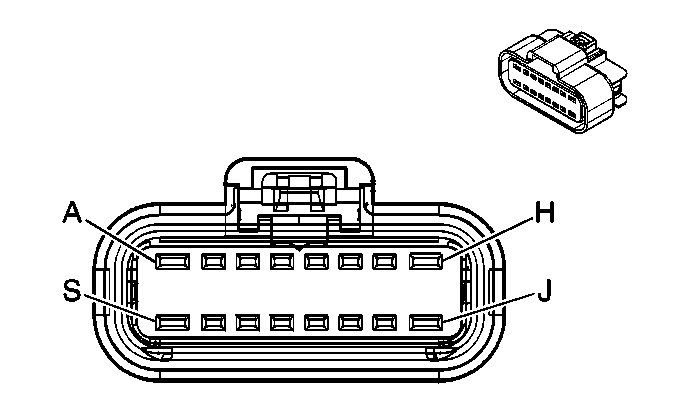
|
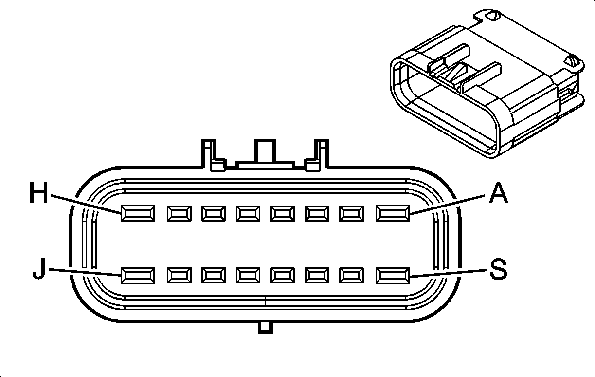
| ||||||||||||||
|---|---|---|---|---|---|---|---|---|---|---|---|---|---|---|---|
Connector Part Information |
| Connector Part Information |
| ||||||||||||
Pin | Wire Color | Circuit No. | Function | Pin | Wire Color | Circuit No. | Function | ||||||||
A | PK | 639 | Ignition 1 Voltage | A | PK | 639 | Ignition 1 Voltage | ||||||||
B | YE | 410 | ECT Sensor Signal | B | YE | 410 | ECT Sensor Signal | ||||||||
C | BK | 1744 | Fuel Injector 1 Control | C | BK | 1744 | Fuel Injector 1 Control | ||||||||
D | L-GN/BK | 1745 | Fuel Injector 2 Control | D | L-GN/BK | 1745 | Fuel Injector 2 Control | ||||||||
E | PK/BK | 1746 | Fuel Injector 3 Control | E | PK/BK | 1746 | Fuel Injector 3 Control | ||||||||
F | L-BU/BK | 844 | Fuel Injector 4 Control | F | L-BU/BK | 844 | Fuel Injector 4 Control | ||||||||
G | BK/WH | 845 | Fuel Injector 5 Control | G | BK/WH | 845 | Fuel Injector 5 Control | ||||||||
H | YE/BK | 846 | Fuel Injector 6 Control | H | YE/BK | 846 | Fuel Injector 6 Control | ||||||||
J | -- | -- | Not Used | J | -- | -- | Not Used | ||||||||
K | GY | 2704 | 5-Volt Reference | K | GY | 2704 | 5-Volt Reference | ||||||||
L | OG/BK | 469 | Low Reference | L | OG/BK | 469 | Low Reference | ||||||||
M | L-GN | 432 | MAP Sensor Signal | M | L-GN | 432 | MAP Sensor Signal | ||||||||
N | RD/WH | 812 | 12-Volt Reference | N | RD/WH | 812 | 12-Volt Reference | ||||||||
P | BK | 407 | Low Reference | P | BK | 407 | Low Reference | ||||||||
R | BN/WH | 633 | CMP Sensor Signal | R | BN/WH | 633 | CMP Sensor Signal | ||||||||
S | -- | -- | Not Used | S | -- | -- | Not Used | ||||||||

|

| ||||||||||||||
|---|---|---|---|---|---|---|---|---|---|---|---|---|---|---|---|
Connector Part Information |
| Connector Part Information |
| ||||||||||||
Pin | Wire Color | Circuit No. | Function | Pin | Wire Color | Circuit No. | Function | ||||||||
A | D-GN | 1049 | PCM Class 2 Serial Data | A | D-GN | 1049 | PCM Class 2 Serial Data | ||||||||
B | BK | 2759 | Low Reference | B | BK | 2759 | Low Reference | ||||||||
C | PU | 420 | TCC Brake Switch/Cruise Control Release Signal (LA1) | C | PU | 420 | TCC Brake Switch/Cruise Control Release Signal (LA1) | ||||||||
WH | 17 | Stop Lamp Switch Signal (LY7) | WH | 17 | Stop Lamp Switch Signall (LY7) | ||||||||||
D | BN/WH | 419 | MIL Control | D | BN/WH | 419 | MIL Control | ||||||||
E | D-GN | 890 | Fuel Tank Pressure Sensor Signal | E | D-GN | 890 | Fuel Tank Pressure Sensor Signal | ||||||||
F | WH | 1310 | EVAP Canister Vent Solenoid Control | F | WH | 1310 | EVAP Canister Vent Solenoid Control | ||||||||
G | D-GN | 389 | Vehicle Speed Signal | G | D-GN | 389 | Vehicle Speed Signal | ||||||||
H | BK/WH | 451 | Ground (LA1) | H | BK/WH | 451 | Ground (LA1) | ||||||||
PU | 420 | TCC Brake Switch/Cruise Control Release Signal (LY7) | PU | 420 | TCC Brake Switch/Cruise Control Release Signal (LY7) | ||||||||||
J | YE | 5 | Crank Voltage | J | YE | 5 | Crank Voltage | ||||||||
K | WH | 85 | Cruise Control Engaged Signal (LA1) | K | WH | 85 | Cruise Control Engaged Signal (LA1) | ||||||||
D-BU | 84 | Cruise Control Set/Coast Switch Signal (LY7) | D-BU | 84 | Cruise Control Set/Coast Switch Signal (LY7) | ||||||||||
L | D-GN | 500 | Ignition 0 Voltage | L | D-GN | 500 | Ignition 0 Voltage | ||||||||
M | GY | 397 | Cruise Control On Switch Signal (LY7) | M | GY | 397 | Cruise Control On Switch Signal (LY7) | ||||||||
N | PU | 1589 | Fuel Level Sensor Signal | N | PU/WH | 1589 | Fuel Level Sensor Signal | ||||||||
P | GY | 2709 | 5-Volt Reference | P | GY | 2709 | 5-Volt Reference | ||||||||
R | D-GN | 83 | Cruise Control Inhibit Signal (LA1) | R | D-GN | 83 | Cruise Control Inhibit Signal (LA1) | ||||||||
GY/BK | 87 | Cruise Control Resume/Accel Switch Signal (LY7) | GY/BK | 87 | Cruise Control Resume/Accel Switch Signal (LY7) | ||||||||||
S | L-BU | 1296 | Axle Actuator - Control (AWD) | S | L-BU | 1296 | Axle Actuator - Control | ||||||||
|
| ||||||||||||||
|---|---|---|---|---|---|---|---|---|---|---|---|---|---|---|---|
Connector Part Information |
| Connector Part Information |
| ||||||||||||
Pin | Wire Color | Circuit No. | Function | Pin | Wire Color | Circuit No. | Function | ||||||||
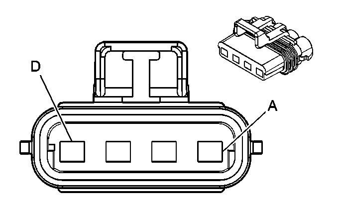
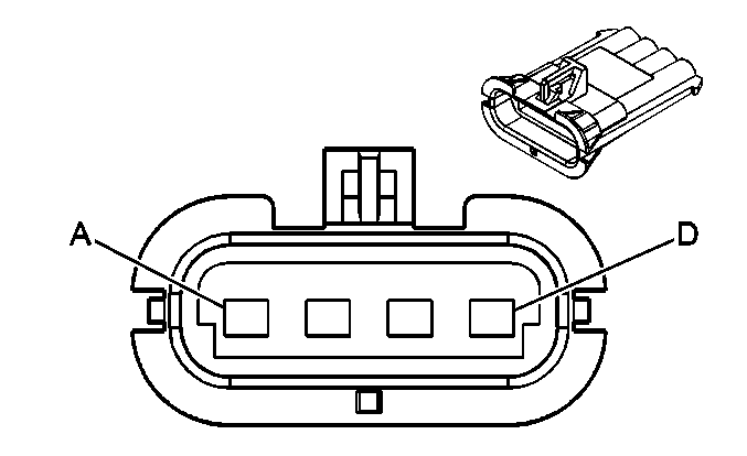
A | BK | 1250 | Ground | A | BK | 1250 | Ground | ||||||||
B | L-BU | 409 | Cooling Fan Motor Supply Voltage | B | RD | 409 | Cooling Fan Motor Supply Voltage | ||||||||
C | GY | 532 | Cooling Fan Motor Supply Voltage | C | RD | 532 | Cooling Fan Motor Supply Voltage | ||||||||
D | WH | 504 | Cooling Fan Motor Ground | D | BK | 504 | Cooling Fan Motor Ground | ||||||||
|
| ||||||||||||||
|---|---|---|---|---|---|---|---|---|---|---|---|---|---|---|---|
Connector Part Information |
| Connector Part Information |
| ||||||||||||
Pin | Wire Color | Circuit No. | Function | Pin | Wire Color | Circuit No. | Function | ||||||||
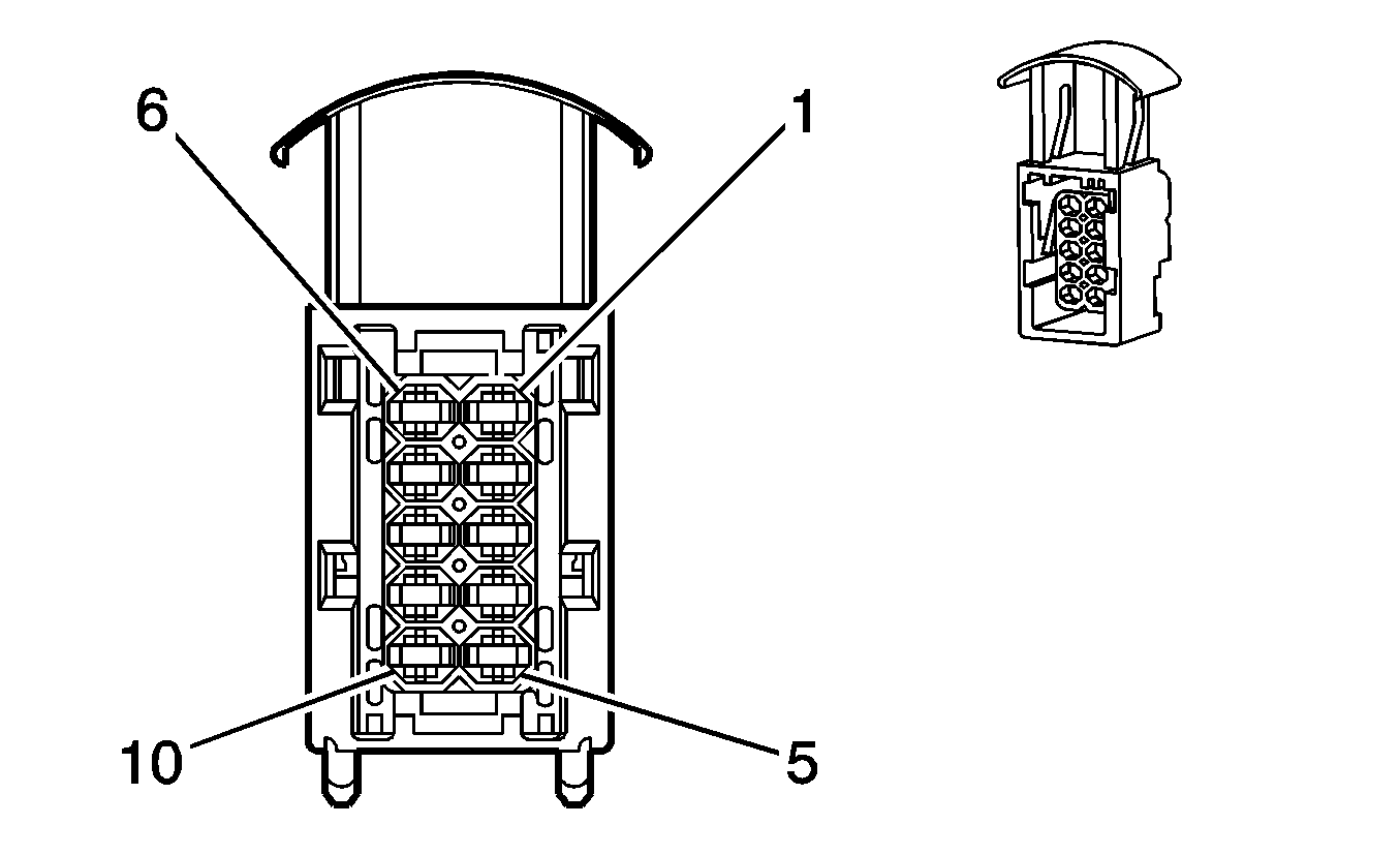
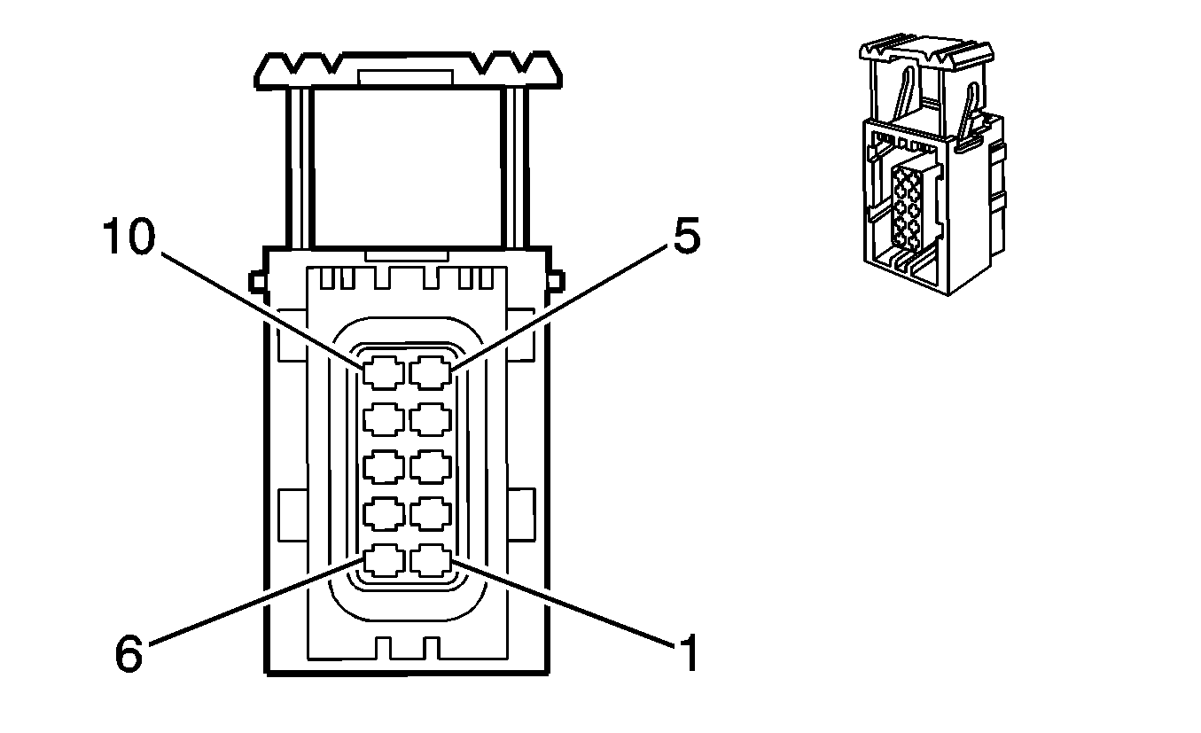
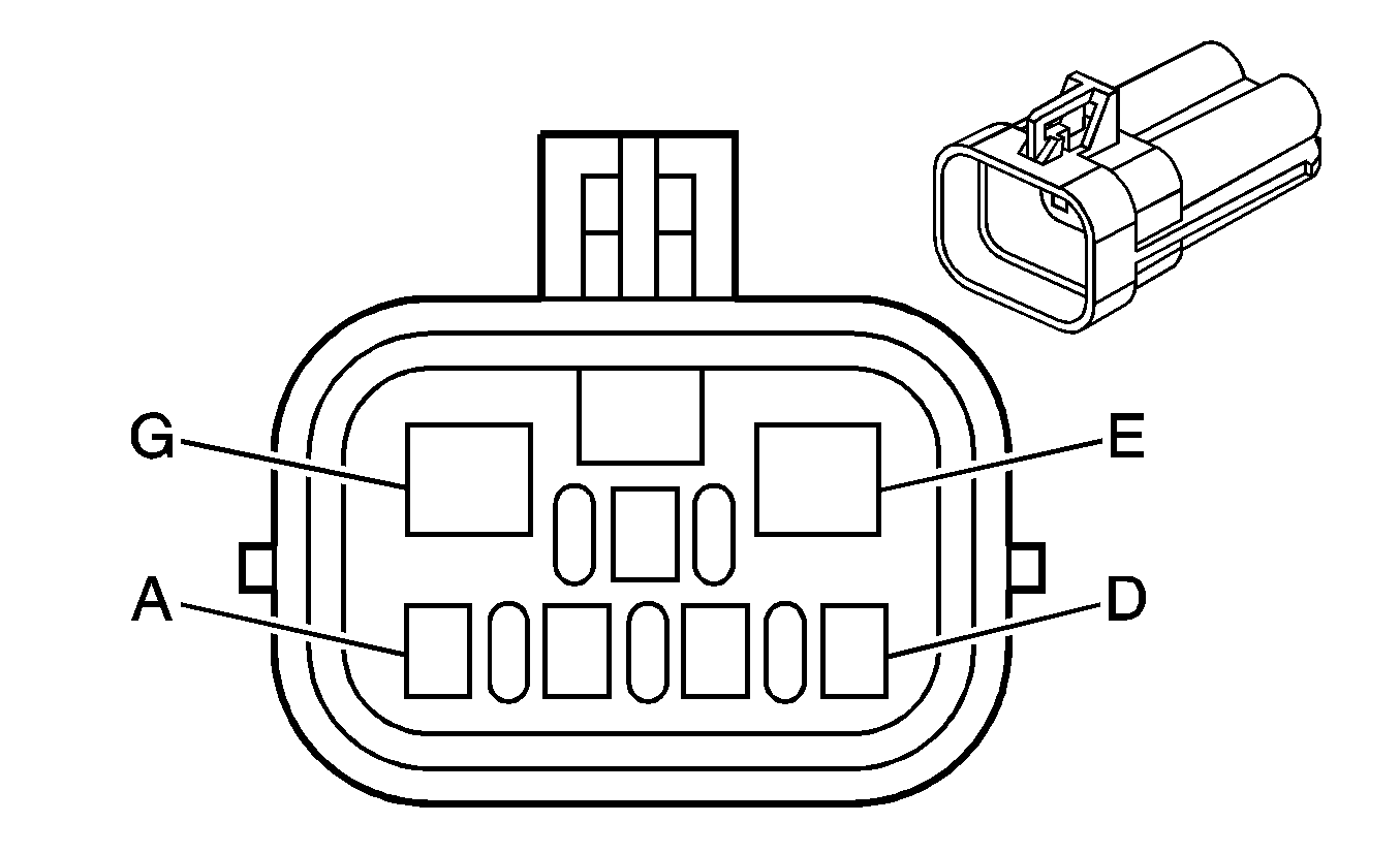
1 | WH | 5291 | Ignition 1 Voltage | 1 | WH | 5291 | Ignition 1 Voltage | ||||||||
2 | WH | 5292 | Ignition 1 Voltage | 2 | WH | 5292 | Ignition 1 Voltage | ||||||||
3 | TN | 1744 | Fuel Injector 1 Control | 3 | TN | 1744 | Fuel Injector 1 Control | ||||||||
4 | PK/BK | 1746 | Fuel Injector 3 Control | 4 | PK/BK | 1746 | Fuel Injector 3 Control | ||||||||
5 | TN/WH | 845 | Fuel Injector 5 Control | 5 | TN/WH | 845 | Fuel Injector 5 Control | ||||||||
6 | L-GN/BK | 1745 | Fuel Injector 2 Control | 6 | L-GN/BK | 1745 | Fuel Injector 2 Control | ||||||||
7 | D-BU/BK | 844 | Fuel Injector 4 Control | 7 | D-BU/BK | 844 | Fuel Injector 4 Control | ||||||||
8 | YE/BK | 846 | Fuel Injector 6 Control | 8 | YE/BK | 846 | Fuel Injector 6 Control | ||||||||
9-10 | -- | -- | Not Used | 9-10 | -- | -- | Not Used | ||||||||

|
| ||||||||||||||
|---|---|---|---|---|---|---|---|---|---|---|---|---|---|---|---|
Connector Part Information |
| Connector Part Information |
| ||||||||||||
Pin | Wire Color | Circuit No. | Function | Pin | Wire Color | Circuit No. | Function | ||||||||
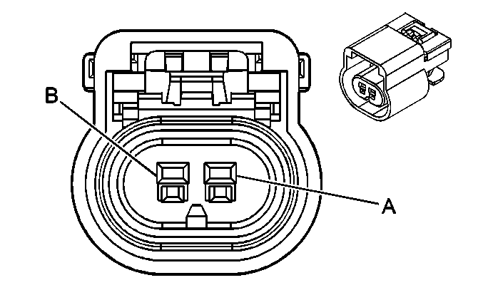
A | PK/BK | 5291 | Ignition 1 Voltage | A | WH | 5291 | Ignition 1 Voltage | ||||||||
B | -- | -- | Not Used | B | -- | -- | Not Used | ||||||||
C | D-GN | 59 | A/C Compressor Clutch Supply Voltage | C | D-GN | 59 | A/C Compressor Clutch Supply Voltage | ||||||||
D | PK/BK | 5292 | Ignition 1 Voltage | D | WH | 5292 | Ignition 1 Voltage | ||||||||
E | PU | 6 | Starter Solenoid Crank Voltage | E | PU | 6 | Starter Solenoid Crank Voltage | ||||||||
F | PK/BK | 5293 | Ignition 1 Voltage | F | WH | 5293 | Ignition 1 Voltage | ||||||||
G | BK/WH | 451 | Ground | G | BK/WH | 451 | Ground | ||||||||
|
| ||||||||||||||
|---|---|---|---|---|---|---|---|---|---|---|---|---|---|---|---|
Connector Part Information |
| Connector Part Information |
| ||||||||||||
Pin | Wire Color | Circuit No. | Function | Pin | Wire Color | Circuit No. | Function | ||||||||
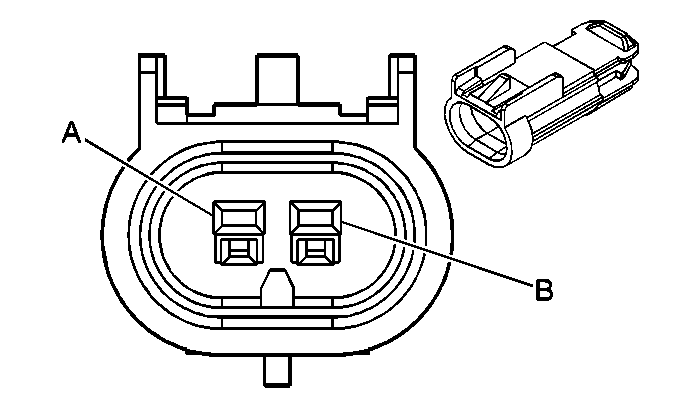
A | L-GN/BK | 735 | Ambient Air Temperature Sensor Signal | A | L-GN/BK | 735 | Ambient Air Temperature Sensor Signal | ||||||||
B | YE | 61 | Low Reference | B | YE | 61 | Low Reference | ||||||||
|
| ||||||||||||||
|---|---|---|---|---|---|---|---|---|---|---|---|---|---|---|---|
Connector Part Information |
| Connector Part Information |
| ||||||||||||
Pin | Wire Color | Circuit No. | Function | Pin | Wire Color | Circuit No. | Function | ||||||||
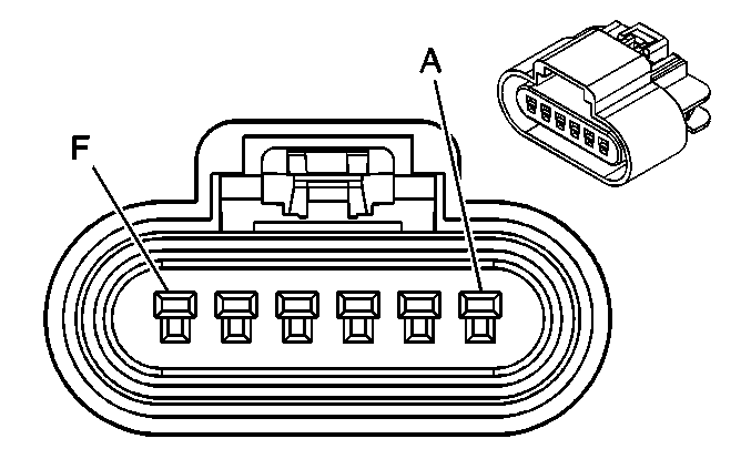
A | L-GN/BK | 735 | Ambient Air Temperature Sensor Signal (UH9/CJ2) | A | L-GN/BK | 735 | Ambient Air Temperature Sensor Signal (UH9/CJ2) | ||||||||
B | YE | 61 | Low Reference (UH9/CJ2) | B | YE | 61 | Low Reference (UH9/CJ2) | ||||||||
C | YE | 9901 | Inflatable Restraint Front End Discriminating Sensor - Left - Signal | C | RD | 9901 | Inflatable Restraint Front End Discriminating Sensor - Left - Signal | ||||||||
D | GY | 9904 | Inflatable Restraint Front End Discriminating Sensor - Left - Voltage | D | BN | 9904 | Inflatable Restraint Front End Discriminating Sensor - Left - Voltage | ||||||||
E | BK | 9906 | Inflatable Restraint Front End Discriminating Sensor - Right - Signal | E | PU | 9906 | Inflatable Restraint Front End Discriminating Sensor - Right - Signal | ||||||||
F | OG | 9902 | Inflatable Restraint Front End Discriminating Sensor - Right - Voltage | F | RD | 9902 | Inflatable Restraint Front End Discriminating Sensor - Right - Voltage | ||||||||
|

| ||||||||||||||
|---|---|---|---|---|---|---|---|---|---|---|---|---|---|---|---|
Connector Part Information |
| Connector Part Information |
| ||||||||||||
Pin | Wire Color | Circuit No. | Function | Pin | Wire Color | Circuit No. | Function | ||||||||
A | YE | 712 | Left Headlamp Low Beam Supply Voltage | A | YE | 712 | Left Headlamp Low Beam Supply Voltage | ||||||||
B | D-GN/WH | 711 | Left Headlamp High Beam Supply Voltage | B | D-GN/WH | 711 | Left Headlamp High Beam Supply Voltage | ||||||||
C | BK | 1350 | Ground | C | BK | 1350 | Ground | ||||||||
D | -- | -- | Not Used | D | -- | -- | Not Used | ||||||||

|

| ||||||||||||||
|---|---|---|---|---|---|---|---|---|---|---|---|---|---|---|---|
Connector Part Information |
| Connector Part Information |
| ||||||||||||
Pin | Wire Color | Circuit No. | Function | Pin | Wire Color | Circuit No. | Function | ||||||||
A | TN/WH | 312 | Right Headlamp Low Beam Supply Voltage | A | TN/WH | 312 | Right Headlamp Low Beam Supply Voltage | ||||||||
B | L-GN/BK | 311 | Right Headlamp High Beam Supply Voltage | B | L-GN/BK | 311 | Right Headlamp High Beam Supply Voltage | ||||||||
C | BK | 1250 | Ground | C | BK | 1250 | Ground | ||||||||
D | D-BU | 593 | DRL Headlamp High Beam Supply Voltage | D | D-BU | 593 | DRL Headlamp High Beam Supply Voltage | ||||||||
|
| ||||||||||||||
|---|---|---|---|---|---|---|---|---|---|---|---|---|---|---|---|
Connector Part Information |
| Connector Part Information |
| ||||||||||||
Pin | Wire Color | Circuit No. | Function | Pin | Wire Color | Circuit No. | Function | ||||||||
A | L-BU | 14 | Left Turn Signal Lamps Supply Voltage | A | L-BU | 14 | Left Turn Signal Lamps Supply Voltage | ||||||||
B | BN | 9 | Park Lamp Supply Voltage | B | BN | 9 | Park Lamp Supply Voltage | ||||||||
C | BK | 1350 | Ground | C | BK | 1350 | Ground | ||||||||

|

| ||||||||||||||
|---|---|---|---|---|---|---|---|---|---|---|---|---|---|---|---|
Connector Part Information |
| Connector Part Information |
| ||||||||||||
Pin | Wire Color | Circuit No. | Function | Pin | Wire Color | Circuit No. | Function | ||||||||
A | L-BU | 15 | Right Turn Signal Lamps Supply Voltage | A | D-BU | 15 | Right Turn Signal Lamps Supply Voltage | ||||||||
B | BN | 9 | Park Lamp Supply Voltage | B | BN | 9 | Park Lamp Supply Voltage | ||||||||
C | BK | 1250 | Ground | C | BK | 1250 | Ground | ||||||||

|

| ||||||||||||||
|---|---|---|---|---|---|---|---|---|---|---|---|---|---|---|---|
Connector Part Information |
| Connector Part Information |
| ||||||||||||
Pin | Wire Color | Circuit No. | Function | Pin | Wire Color | Circuit No. | Function | ||||||||
A | YE | 712 | Left Headlamp Low Beam Supply Voltage | A | YE | 712 | Left Headlamp Low Beam Supply Voltage | ||||||||
B | D-GN/WH | 711 | Left Headlamp High Beam Supply Voltage | B | D-GN/WH | 711 | Left Headlamp High Beam Supply Voltage | ||||||||
C | BK | 1350 | Ground | C | BK | 1350 | Ground | ||||||||
D | -- | -- | Not Used | D | -- | -- | Not Used | ||||||||
E | BN | 9 | Park Lamp Supply Voltage | E | BN | 9 | Park Lamp Supply Voltage | ||||||||
F | L-BU | 14 | Left Turn Signal Supply Voltage | F | L-BU | 14 | Left Turn Signal Lamps Supply Voltage | ||||||||

|

| ||||||||||||||
|---|---|---|---|---|---|---|---|---|---|---|---|---|---|---|---|
Connector Part Information |
| Connector Part Information |
| ||||||||||||
Pin | Wire Color | Circuit No. | Function | Pin | Wire Color | Circuit No. | Function | ||||||||
A | TN/WH | 312 | Right Headlamp Low Beam Supply Voltage | A | TN/WH | 312 | Right Headlamp Low Beam Supply Voltage | ||||||||
B | L-GN/BK | 311 | Right Headlamp High Beam Supply Voltage | B | L-GN/BK | 311 | Right Headlamp High Beam Supply Voltage | ||||||||
C | BK | 1250 | Ground | C | BK | 1250 | Ground | ||||||||
D | D-BU | 593 | DRL Headlamp High Beam Supply Voltage | D | D BU | 593 | DRL Headlamp High Beam Supply Voltage | ||||||||
E | BN | 9 | Park Lamp Supply Voltage | E | BN | 9 | Park Lamp Supply Voltage | ||||||||
F | D-BU | 15 | Right Turn Signal Supply Voltage | F | D-BU | 15 | Right Turn Signal Supply Voltage | ||||||||
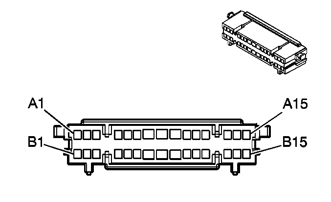
|
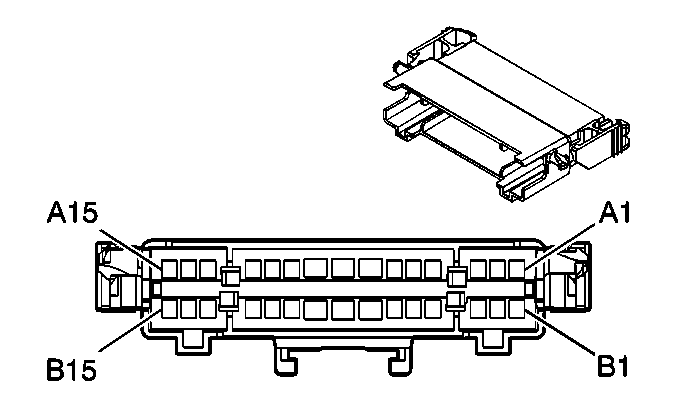
| ||||||||||||||
|---|---|---|---|---|---|---|---|---|---|---|---|---|---|---|---|
Connector Part Information |
| Connector Part Information |
| ||||||||||||
Pin | Wire Color | Circuit No. | Function | Pin | Wire Color | Circuit No. | Function | ||||||||
A1 | L-BU/BK | 315 | Right Subwoofer Speaker Output (-) (UQ3) | A1 | L-BU/BK | 315 | Right Subwoofer Speaker Output (-) (UQ3) | ||||||||
A2 | D-GN | 1795 | Right Subwoofer Speaker Output (+) (UQ3) | A2 | D-GN | 1795 | Right Subwoofer Speaker Output (+) (UQ3) | ||||||||
A3 | BN/WH | 2517 | Keypad Red LED Signal (UE1) | A3 | BN/WH | 2517 | Keypad Red LED Signal (UE1) | ||||||||
A4 | YE/BK | 2516 | Keypad Green LED Signal (UE1) | A4 | YE/BK | 2516 | Keypad Green LED Signal (UE1) | ||||||||
A5 | D-GN/WH | 2514 | Keypad Signal (UE1) | A5 | D-GN/WH | 2514 | Keypad Signal (UE1) | ||||||||
A6 | OG/BK | 2518 | Keypad Low Reference (UE1) | A6 | OG/BK | 2518 | Keypad Low Reference (UE1) | ||||||||
A7 | PK | 1439 | Ignition 1 Voltage | A7 | PK | 1439 | Ignition 1 Voltage (AWD) | ||||||||
PK | 1439 | Ignition 1 Voltage (UD7) | |||||||||||||
A8 | GY | 391 | Rear Window Wiper Switch Signal (Buick) | A8 | GY | 391 | Rear Window Wiper Switch Signal (Buick) | ||||||||
A9 | GY | 120 | Fuel Pump Supply Voltage | A9 | GY | 120 | Fuel Pump Supply Voltage | ||||||||
A10 | L-GN/BK | 2515 | Keypad Supply Voltage (UE1) | A10 | L-GN/BK | 2515 | Keypad Supply Voltage (UE1) | ||||||||
A11 | GY | 655 | Cellular Microphone Signal (UE1) | A11 | GY | 655 | Cellular Microphone Signal (UE1) | ||||||||
A12 | BARE | 1705 | Drain Wire (UE1) | A12 | BARE | 1705 | Drain Wire (UE1) | ||||||||
A13 | D-GN | 392 | Rear Window Washer Pump Control (Buick) | A13 | D-GN | 392 | Rear Window Washer Pump Control (Buick) | ||||||||
A14-A15 | -- | -- | Not Used | A14-A15 | -- | -- | Not Used | ||||||||
B1 | RD | 1955 | Right Rear Midrange Speaker Output (-) (Pontiac/UQ3) | B1 | RD | 1955 | Right Rear Midrange Speaker Output (-) (Pontiac/UQ3) | ||||||||
D-GN | 117 | Right Front Speaker Output (-) (Buick) | PU | 117 | Right Front Tweeter Speaker Output (-) (Buick w/o UQ3) | ||||||||||
PU | 1952 | Right Front Tweeter Speaker Output (-) (Buick/UQ3) | |||||||||||||
B2 | TN | 1855 | Right Rear Midrange Speaker Output (+) (Pontiac/UQ3) | B2 | TN | 1855 | Right Rear Midrange Speaker Output (+) (Pontiac/UQ3) | ||||||||
L-GN | 200 | Right Front Speaker Output (+) (Buick) | L-GN | 200 | Right Front Tweeter Speaker Output (+) (Buick w/o UQ3) | ||||||||||
L-GN | 1852 | Right Front Tweeter Speaker Output (+) (Buick/UQ3) | |||||||||||||
B3-B4 | -- | -- | Not Used | B3-B4 | -- | -- | Not Used | ||||||||
B5 | L-BU/BK | 1505 | Passenger Heated Seat Switch Signal (KA1) | B5 | L-BU/BK | 1505 | Passenger Heated Seat Switch Signal (KA1) | ||||||||
B6 | -- | -- | Not Used | B6 | -- | -- | Not Used | ||||||||
B7 | D-GN | 117 | Right Front Speaker Output (-) | B7 | D-GN | 117 | Right Front Speaker Output (-) | ||||||||
D-GN | 117 | Right Front Speaker Output (-) (Pontiac) | D-GN | 117 | Right Front Speaker Output (-) (Buick w/o UQ3) | ||||||||||
B8 | L-GN | 200 | Right Front Speaker Output (+) | B8 | L-GN | 200 | Right Front Speaker Output (+) | ||||||||
L-GN | 200 | Right Front Speaker Output (+) (Pontiac) | L-GN | 200 | Right Front Speaker Output (+) (Buick w/o UQ3) | ||||||||||
B9 | D-BU | 1796 | Steering Wheel Controls Signal (Pontiac/UQ3) | B9 | D-BU | 1796 | Steering Wheel Controls Signal (Pontiac/UQ3) | ||||||||
D-BU | 1796 | Steering Wheel Controls Signal (Pontiac/UQ3) | |||||||||||||
B10 | RD | 9901 | Inflatable Restraint Front End Discriminating Sensor - Left - Signal (Buick) | B10 | RD | 9901 | Inflatable Restraint Front End Discriminating Sensor - Left - Signal (Buick) | ||||||||
B11 | BN | 9904 | Inflatable Restraint Front End Discriminating Sensor - Left - Voltage (Buick) | B11 | BN | 9904 | Inflatable Restraint Front End Discriminating Sensor - Left - Voltage (Buick) | ||||||||
B12 | RD | 9906 | Inflatable Restraint Front End Discriminating Sensor - Right - Signal (Buick) | B12 | RD | 9906 | Inflatable Restraint Front End Discriminating Sensor - Right - Signal (Buick) | ||||||||
B13 | PU | 9902 | Inflatable Restraint Front End Discriminating Sensor - Right - Voltage (Buick) | B13 | PU | 9902 | Inflatable Restraint Front End Discriminating Sensor - Right - Voltage (Buick) | ||||||||
B14 | OG | 4540 | Battery Positive Voltage | B14 | OG | 4540 | Battery Positive Voltage | ||||||||
B15 | -- | -- | Not Used | B15 | -- | -- | Not Used | ||||||||
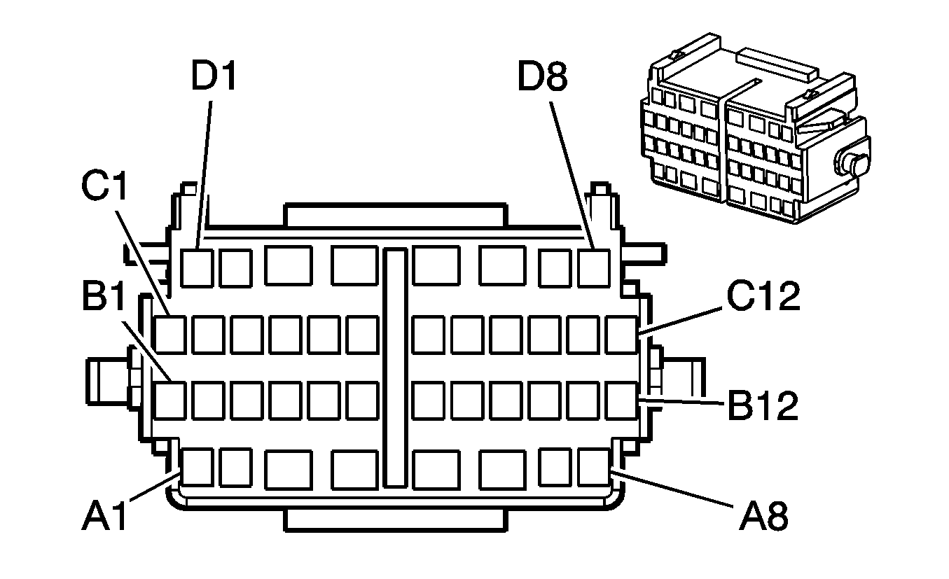
|
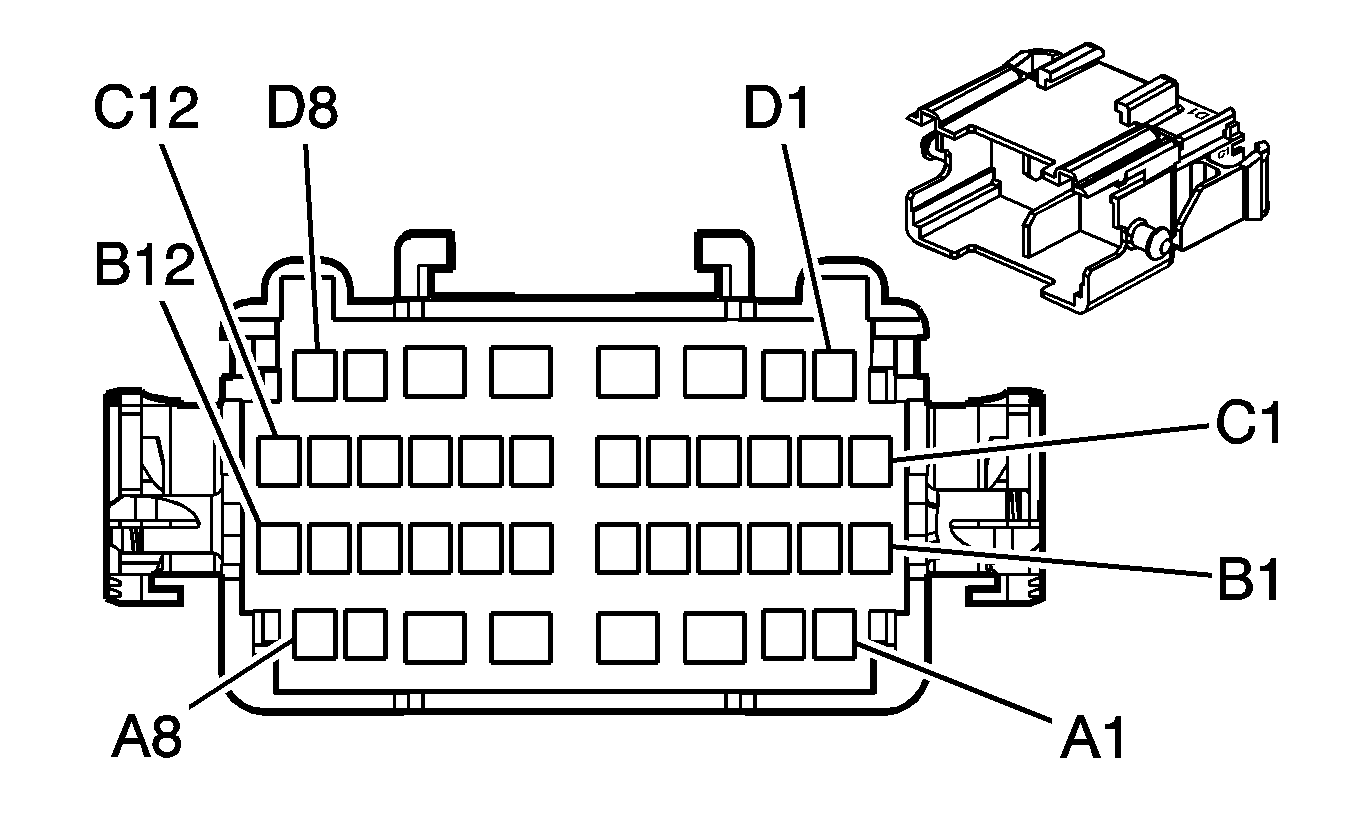
| ||||||||||||||
|---|---|---|---|---|---|---|---|---|---|---|---|---|---|---|---|
Connector Part Information |
| Connector Part Information |
| ||||||||||||
Pin | Wire Color | Circuit No. | Function | Pin | Wire Color | Circuit No. | Function | ||||||||
A1 | OG | 300 | Ignition 3 Voltage | A1 | OG | 300 | Ignition 3 Voltage | ||||||||
A2 | YE | 5 | Crank Voltage | A2 | YE | 5 | Crank Voltage | ||||||||
A3 | PK | 3 | Ignition 1 Voltage | A3 | PK | 3 | Ignition 1 Voltage | ||||||||
A4 | BN | 4 | Accessory Voltage | A4 | BN | 4 | Accessory Voltage | ||||||||
A5 | OG | 1040 | Battery Positive Voltage | A5 | OG | 1040 | Battery Positive Voltage | ||||||||
A6 | YE | 243 | Accessory Voltage | A6 | YE | 243 | Accessory Voltage | ||||||||
A7 | D-GN | 500 | Ignition 0 Voltage | A7 | D-GN | 500 | Ignition 0 Voltage | ||||||||
A8 | OG | 2340 | Battery Positive Voltage | A8 | OG | 2340 | Battery Positive Voltage | ||||||||
B1 | BK | 1550 | Ground | B1 | BK | 1550 | Ground | ||||||||
B2 | L-GN | 80 | Key In Ignition Switch Signal | B2 | L-GN | 80 | Key In Ignition Switch Signal | ||||||||
B3 | PU | 1807 | Class 2 Serial Data (Primary) | B3 | PU | 1807 | Class 2 Serial Data (Primary) | ||||||||
B4 | L-BU | 1134 | Park Position Switch Signal (Pontiac) | B4 | L-BU | 1134 | Park Position Switch Signal (Pontiac) | ||||||||
D-GN/WH | 1135 | A/T Shift Lock Control Solenoid Supply Voltage (Buick) | D-GN/WH | 1135 | A/T Shift Lock Control Solenoid Supply Voltage (Buick) | ||||||||||
B5 | BK | 1450 | Ground | B5 | BK | 1450 | Ground | ||||||||
B6 | OG | 2340 | Battery Positive Voltage | B6 | OG | 2340 | Battery Positive Voltage | ||||||||
B7 | PU | 1500 | Ignition 0 Voltage | B7 | PU | 1500 | Ignition 0 Voltage | ||||||||
B8 | PK | 39 | Ignition 1 Voltage | B8 | PK | 39 | Ignition 1 Voltage | ||||||||
B9 | GY | 397 | Cruise Control On Switch Signal | B9 | GY | 397 | Cruise Control On Switch Signal | ||||||||
B10 | D-BU | 84 | Cruise Control Set/Coast Switch Signal | B10 | D-BU | 84 | Cruise Control Set/Coast Switch Signal | ||||||||
B11 | GY/BK | 87 | Cruise Control Resume/Accel Switch Signal | B11 | GY/BK | 87 | Cruise Control Resume/Accel Switch Signal | ||||||||
B12 | PU | 1375 | Remote Radio Control Supply Voltage | B12 | PU | 1375 | Remote Radio Control Supply Voltage | ||||||||
C1 | PK | 539 | Ignition 1 Voltage | C1 | PK | 539 | Ignition 1 Voltage | ||||||||
C2 | L-BU/WH | 1414 | Turn Signal Switch Left Signal | C2 | L-BU/WH | 1414 | Turn Signal Switch Left Signal | ||||||||
C3 | D-BU/WH | 1415 | Turn Signal Switch Right Signal | C3 | D-BU/WH | 1415 | Turn Signal Switch Right Signal | ||||||||
C4 | TN | 2144 | Hazard Switch Signal | C4 | TN | 2144 | Hazard Switch Signal | ||||||||
C5 | BK | 28 | Horn Relay Control | C5 | BK | 28 | Horn Relay Control | ||||||||
C6-C11 | -- | -- | Not Used | C6-C11 | -- | -- | Not Used | ||||||||
C12 | BK | 910 | Headlamp Low/High Beam Relay Control | C12 | L-BU | 910 | Headlamp Low/High Beam Relay Control | ||||||||
D1 | BK/WH | 1969 | Headlamp High Beam Relay Control | D1 | BK/WH | 1969 | Headlamp High Beam Relay Control | ||||||||
D2 | PK/WH | 1970 | Headlamp Low Beam Relay Control | D2 | PK/WH | 1970 | Headlamp Low Beam Relay Control | ||||||||
D3 | GY | 112 | Windshield Wiper Switch Signal 1 | D3 | GY | 112 | Windshield Wiper Switch Signal 1 | ||||||||
D4 | D-GN | 113 | Windshield Wiper Switch Signal 2 | D4 | D-GN | 113 | Windshield Wiper Switch Signal 2 | ||||||||
D5 | PU | 92 | Windshield Wiper Motor High Speed | D5 | PU | 92 | Windshield Wiper Motor High Speed | ||||||||
D6 | RD | 228 | Washer Pump Control | D6 | RD | 228 | Windshield Washer Pump Control | ||||||||
D7 | D-BU | 1796 | Steering Wheel Controls Signal | D7 | D-BU | 1796 | Steering Wheel Controls Signal | ||||||||
D8 | GY/BK | 1458 | Instrument Panel Lamp Supply Voltage 4 | D8 | GY/BK | 1458 | Instrument Panel Lamp Supply Voltage 4 | ||||||||
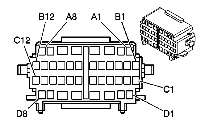
|
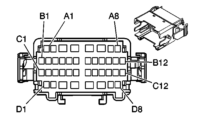
| ||||||||||||||
|---|---|---|---|---|---|---|---|---|---|---|---|---|---|---|---|
Connector Part Information |
| Connector Part Information |
| ||||||||||||
Pin | Wire Color | Circuit No. | Function | Pin | Wire Color | Circuit No. | Function | ||||||||
A1 | BK | 884 | Left Rear Wheel Speed Sensor Signal | A1 | BK | 884 | Left Rear Wheel Speed Sensor Signal | ||||||||
A2 | RD | 885 | Left Rear Wheel Speed Sensor Low Reference | A2 | RD | 885 | Left Rear Wheel Speed Sensor Low Reference | ||||||||
A3 | TN | 201 | Left Front Speaker Output (+) | A3 | TN | 201 | Left Front Speaker Output (+) | ||||||||
TN | 201 | Left Front Speaker Output (+) (Pontiac) | TN | 201 | Left Front Speaker Output (+) (Buick w/o UQ3) | ||||||||||
A4 | GY | 118 | Left Front Speaker Output (-) | A4 | GY | 118 | Left Front Speaker Output (-) | ||||||||
GY | 118 | Left Front Speaker Output (-) (Pontiac) | GY | 118 | Left Front Speaker Output (-) (Buick w/o UQ3) | ||||||||||
A5 | BN | 1999 | Left Rear Low Level Audio Signal (-) (Pontiac/UK6) | A5 | BN | 1999 | Left Rear Low Level Audio Signal (-) (Pontiac w/o UQ3) | ||||||||
BN | 1999 | Left Rear Low Level Audio Signal (-) (Pontiac w/o UQ3) | |||||||||||||
A6 | BN/WH | 599 | Left Rear Low Level Audio Signal (+) (Pontiac/UK6) | A6 | BN/WH | 599 | Left Rear Low Level Audio Signal (+) (Pontiac w/o UQ3) | ||||||||
BN/WH | 599 | Left Rear Low Level Audio Signal (+) (Pontiac w/o UQ3) | |||||||||||||
A7 | BN | 199 | Left Rear Speaker Output (+) | A7 | BN | 199 | Left Rear Speaker Output (+) | ||||||||
A8 | WH | 883 | Right Rear Wheel Speed Sensor Low Reference | A8 | WH | 883 | Right Rear Wheel Speed Sensor Low Reference | ||||||||
B1 | PU | 1589 | Fuel Level Sensor Signal - Primary | B1 | PU/WH | 1589 | Fuel Level Sensor Signal | ||||||||
B2 | L-BU | 1296 | Axle Actuator - Control (M76) | B2 | L-BU | 1296 | Axle Actuator - Control (M76) | ||||||||
B3 | BN | 9380 | Rear Parking Assist Disable Switch Input (UD7) | B3 | L-GN | 9380 | Rear Parking Assist Disable Switch Input (UD7) | ||||||||
B4 | GY | 2709 | 5-Volt Reference | B4 | GY | 2709 | 5-Volt Reference | ||||||||
B5 | YE | 116 | Left Rear Speaker Output (-) | B5 | YE | 116 | Left Rear Speaker Output (-) | ||||||||
B6 | BARE | 814 | Rear Seat Audio Enable Signal (U32) | B6 | BARE | 814 | Rear Seat Audio Enable Signal (U32) | ||||||||
B7 | OG | 4240 | Battery Positive Voltage (U32) | B7 | OG | 4240 | Battery Positive Voltage (U32) | ||||||||
B8 | D-GN | 890 | Fuel Tank Pressure Sensor Signal | B8 | D-GN | 890 | Fuel Tank Pressure Sensor Signal | ||||||||
B9 | BK | 2759 | Low Reference | B9 | BK | 2759 | Low Reference | ||||||||
B10 | -- | -- | Not Used | B10 | -- | -- | Not Used | ||||||||
B11 | BN | 882 | Right Rear Wheel Speed Sensor Signal (JM4/JL9) | B11 | BN | 882 | Right Rear Wheel Speed Sensor Signal (JM4/JL9) | ||||||||
B12 | L-BU | 1462 | Driver Heated Seat Switch Signal (KA1) | B12 | L-BU | 1462 | Driver Heated Seat Switch Signal (KA1) | ||||||||
C1 | BK/WH | 351 | Ground (U32) | C1 | BK/WH | 351 | Ground (U32) | ||||||||
C2 | PK | 1045 | RFA Class 2 Serial Data (U32) | C2 | PK | 1045 | RFA Class 2 Serial Data (U32) | ||||||||
C3 | BN/WH | 367 | Remote Radio Left Audio Signal | C3 | BN/WH | 367 | Remote Radio Left Audio Signal | ||||||||
C4 | BN | 9 | Park Lamp Supply Voltage | C4 | BN | 9 | Park Lamp Supply Voltage | ||||||||
C5 | WH | 1310 | EVAP Canister Vent Solenoid Control | C5 | WH | 1310 | EVAP Canister Vent Solenoid Control | ||||||||
C6 | D-GN | 389 | Vehicle Speed Signal | C6 | D-GN | 389 | Vehicle Speed Signal | ||||||||
C7 | BN/WH | 1048 | SCM (Seat) Class 2 Serial Data (A43) | C7 | BN/WH | 1048 | SCM (Seat) Class 2 Serial Data (A43) | ||||||||
C8 | GN/WH | 368 | Remote Radio Right Audio Signal (U32) | C8 | GN/WH | 368 | Remote Radio Right Audio Signal (U32) | ||||||||
C9 | BK/WH | 372 | Remote Radio Audio Output (-) (U32) | C9 | BK/WH | 372 | Remote Radio Audio Output (-) (U32) | ||||||||
C10 | L-BU | 115 | Right Rear Speaker Output (-) | C10 | L-BU | 115 | Right Rear Speaker Output (-) | ||||||||
C11 | D-BU | 46 | Right Rear Speaker Output (+) | C11 | D-BU | 46 | Right Rear Speaker Output (+) | ||||||||
C12 | -- | -- | Not Used | C12 | -- | -- | Not Used | ||||||||
D1 | L-GN/BK | 1794 | Left Rear Subwoofer Speaker Output (-) (Pontiac w/UQ3 or Buick) | D1 | L-GN/BK | 1794 | Left Rear Subwoofer Speaker Output (-) (UQ3) | ||||||||
D2 | D-BU/WH | 346 | Left Rear Subwoofer Speaker Output (+) (Pontiac w/UQ3 or Buick) | D2 | D-BU/WH | 346 | Left Rear Subwoofer Speaker Output (+) (UQ3) | ||||||||
D3 | D-BU | 1128 | SDM Class 2 Serial Data | D3 | D-BU | 1128 | SDM Class 2 Serial Data | ||||||||
D3 | D-BU | 1128 | SDM Class 2 Serial Data | ||||||||||||
D4 | WH/BK | 1221 | Lift Gate Release Switch Signal | D4 | WH/BK | 1221 | Lift Gate Release Switch Signal | ||||||||
D5-D6 | -- | -- | Not Used | D5-D6 | -- | -- | Not Used | ||||||||
D7 | WH | 1959 | Left Rear Midrange Speaker Output (-) (Pontiac/UQ3) | D7 | WH | 1959 | Left Rear Midrange Speaker Output (-) (Pontiac w/UQ3) | ||||||||
GY | 118 | Left Front Tweeter Speaker Output (-) (Buick) | YE | 1956 | Left Front Tweeter Speaker Output (-) (Buick w/UQ3) | ||||||||||
GY | 118 | LF Speaker Output (-) (Buick w/o UQ3) | |||||||||||||
D8 | TN | 1859 | Left Rear Midrange Speaker Output (+) (Pontiac/UQ3) | D8 | TN | 1859 | Left Rear Midrange Speaker Output (+) (Pontiac w/UQ3) | ||||||||
TN | 201 | Left Front Tweeter Speaker Output (+) (Buick) | BK | 1856 | Left Front Tweeter Speaker Output (+) (Buick w/UQ3) | ||||||||||
TN | 201 | LF Speaker Output (+) (Buick w/o UQ3) | |||||||||||||
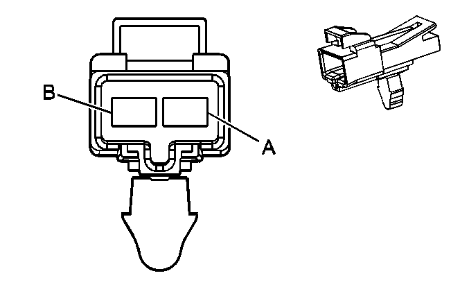
|
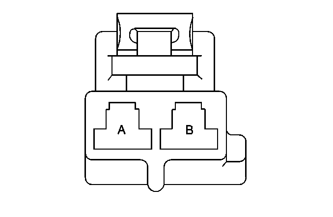
| ||||||||||||||
|---|---|---|---|---|---|---|---|---|---|---|---|---|---|---|---|
Connector Part Information |
| Connector Part Information |
| ||||||||||||
Pin | Wire Color | Circuit No. | Function | Pin | Wire Color | Circuit No. | Function | ||||||||
A | OG | 2740 | Battery Positive Voltage | A | OG | 2740 | Battery Positive Voltage | ||||||||
B | BK | 150 | Ground | B | BK | 150 | Ground | ||||||||
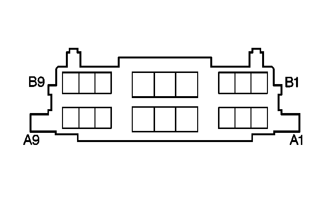
|
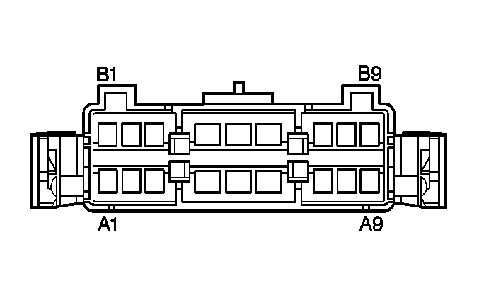
| ||||||||||||||
|---|---|---|---|---|---|---|---|---|---|---|---|---|---|---|---|
Connector Part Information |
| Connector Part Information |
| ||||||||||||
Pin | Wire Color | Circuit No. | Function | Pin | Wire Color | Circuit No. | Function | ||||||||
A1 | OG | 2740 | Battery Positive Voltage | A1 | OG | 2740 | Battery Positive Voltage | ||||||||
A2 | BN | 9 | Park Lamp Supply Voltage | A2 | BN | 9 | Park Lamp Supply Voltage | ||||||||
A3 | OG | 1732 | Courtesy Lamp Supply Voltage | A3 | OG | 1732 | Courtesy Lamp Supply Voltage | ||||||||
A4 | YE | 116 | Left Rear Speaker Output (-) (w/o UQ3) | A4 | YE | 116 | Left Rear Speaker Output (-) (w/o UQ3) | ||||||||
BN | 1999 | Left Rear Low Level Audio Signal (-) (UQ3) | BN | 1999 | Left Rear Low Level Audio Signal (-) (UQ3) | ||||||||||
BN | 1999 | Left Rear Low Level Audio Signal (-) (UQ3) | |||||||||||||
A5 | L-BU | 115 | Right Rear Speaker Output (-) (w/o UQ3) | A5 | L-BU | 115 | Right Rear Speaker Output (-) (w/o UQ3) | ||||||||
BK/WH | 1946 | Right Rear Low Level Audio Signal (-) (UQ3) | BK | 1946 | Right Rear Low Level Audio Signal (-) (UQ3) | ||||||||||
BK/WH | 1946 | Right Rear Low Level Audio Signal (-) (UQ3) | |||||||||||||
A6 | PU | 1375 | Remote Radio Control Supply Voltage | A6 | PU | 1375 | Remote Radio Control Supply Voltage (UK6) | ||||||||
PU | 1375 | Remote Radio Control Supply Voltage | |||||||||||||
A7 | BN | 199 | Left Rear Speaker Output (+) (w/o UQ3) | A7 | BN | 199 | Left Rear Speaker Output (+) | ||||||||
A8 | YE | 116 | Left Rear Speaker Output (-) (w/o UQ3) | A8 | YE | 116 | Left Rear Speaker Output (-) | ||||||||
A9 | -- | -- | Not Used | A9 | -- | -- | Not Used | ||||||||
B1 | BK | 150 | Ground | B1 | BK | 150 | Ground | ||||||||
B2 | -- | -- | Not Used | B2 | -- | -- | Not Used | ||||||||
B3 | GY | 8 | Instrument Panel Lamp Supply Voltage | B3 | GY | 8 | Instrument Panel Lamp Supply Voltage | ||||||||
B4 | PU | 493 | Rear Seat Audio Enable Signal | B4 | PU | 493 | Rear Seat Audio Enable Signal (UK6) | ||||||||
PU | 493 | Rear Seat Audio Enable Signal (UK6) | |||||||||||||
B5 | BN | 199 | Left Rear Speaker Output (+) (w/o UQ3) | B5 | BN | 199 | Left Rear Speaker Output (+) (w/o UQ3) | ||||||||
BN/WH | 599 | Left Rear Low Level Audio Signal (+) (UQ3) | BN | 599 | Left Rear Low Level Audio Signal (+) (UQ3) | ||||||||||
BN/WH | 599 | Left Rear Low Level Audio Signal (+) (UQ3) | |||||||||||||
B6 | D-BU | 46 | Right Rear Speaker Output (+) (w/o UQ3) | B6 | D-BU | 46 | Right Rear Speaker Output (+) (w/o UQ3) | ||||||||
D-BU | 546 | Right Rear Low Level Audio Signal (+) (UQ3) | D-BU | 546 | Right Rear Low Level Audio Signal (+) (UQ3) | ||||||||||
D-BU | 546 | Right Rear Low Level Audio Signal (+) (UQ3) | |||||||||||||
B7 | D-BU | 46 | Right Rear Speaker Output (+) (w/o UQ3) | B7 | D-BU | 46 | Right Rear Speaker Output (+) | ||||||||
B8 | L-GN | 1011 | Remote Radio Control Signal | B8 | L-GN | 1011 | Remote Radio Control Signal (UK6) | ||||||||
B9 | L-BU | 115 | Right Rear Speaker Output (-) (w/o UQ3) | B9 | L-BU | 115 | Right Rear Speaker Output (-) | ||||||||
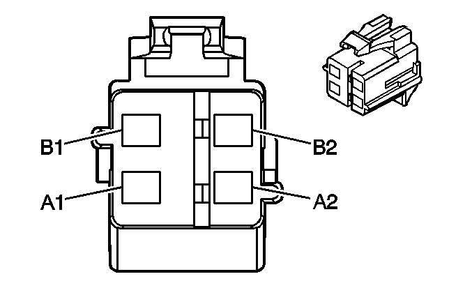
|
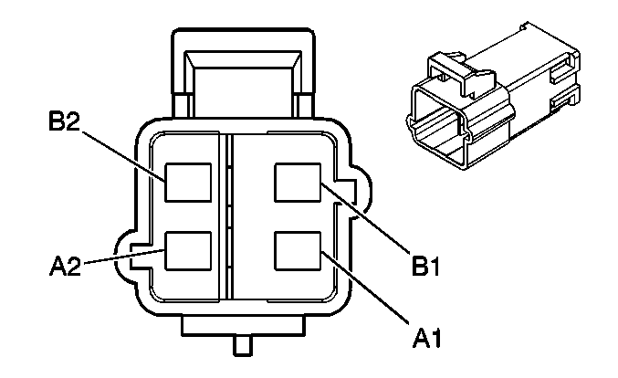
| ||||||||||||||
|---|---|---|---|---|---|---|---|---|---|---|---|---|---|---|---|
Connector Part Information |
| Connector Part Information |
| ||||||||||||
Pin | Wire Color | Circuit No. | Function | Pin | Wire Color | Circuit No. | Function | ||||||||
A1 | TN | 3021 | Steering Wheel Module - Stage1 - High Control | A1 | TN | 3021 | Steering Wheel Module - Stage1 - High Control | ||||||||
A2 | BN | 3020 | Steering Wheel Module - Stage1 - Low Control | A2 | BN | 3020 | Steering Wheel Module - Stage1 - Low Control | ||||||||
B1 | WH | 3023 | Steering Wheel Module - Stage2 - High Control | B1 | WH | 3023 | Steering Wheel Module - Stage2 - High Control | ||||||||
B2 | PK | 3022 | Steering Wheel Module - Stage2 - Low Control | B2 | PK | 3022 | Steering Wheel Module - Stage2 - Low Control | ||||||||

|

| ||||||||||||||
|---|---|---|---|---|---|---|---|---|---|---|---|---|---|---|---|
Connector Part Information |
| Connector Part Information |
| ||||||||||||
Pin | Wire Color | Circuit No. | Function | Pin | Wire Color | Circuit No. | Function | ||||||||
A1 | L-GN | 1514 | Driver Mirror Switch Down Signal (A43) | A1 | L-GN | 1514 | Driver Mirror Switch Down Signal (A43) | ||||||||
A2-A3 | -- | -- | Not Used | A2-A3 | -- | -- | Not Used | ||||||||
A4 | D-BU | 1307 | Power Window Master Switch Lockout Signal | A4 | D-BU | 1307 | Power Window Master Switch Lockout Signal | ||||||||
A5 | PU | 169 | Power Window Master Switch Left Rear Down Signal | A5 | PU | 169 | Power Window Master Switch Left Rear Down Signal | ||||||||
A6 | D-GN | 168 | Power Window Master Switch Left Rear Up Signal | A6 | D-GN | 168 | Power Window Master Switch Left Rear Up Signal | ||||||||
A7 | PU/WH | 1515 | Passenger Mirror Switch Down Signal (A43) | A7 | PU/WH | 1515 | Passenger Mirror Switch Down Signal (A43) | ||||||||
A8 | YE | 1496 | Mirror Motor Left/Up Control (A43) | A8 | YE | 1496 | Mirror Motor Left/up Control (A43) | ||||||||
B1 | WH | 1512 | Driver Mirror Switch Right Signal (A43) | B1 | WH | 1512 | Driver Mirror Switch Right Signal (A43) | ||||||||
B2 | GY | 118 | Left Front Speaker Output (-) | B2 | GY | 118 | Left Front Speaker Output (-) | ||||||||
B3 | GY | 118 | Left Front Speaker Output (-) | B3 | GY | 118 | Left Front Speaker Output (-) | ||||||||
B4 | D-BU/WH | 727 | Right Front Door Open Switch Signal | B4 | D-BU/WH | 727 | Right Front Door Open Switch Signal | ||||||||
B5 | RD/WH | 1513 | Passenger Mirror Switch Right Signal (A43) | B5 | RD/WH | 1513 | Passenger Mirror Switch Right Signal (A43) | ||||||||
B6 | GY | 915 | Mirror Switch Supply Voltage (A43) | B6 | GY | 915 | Mirror Switch Supply Voltage (A43) | ||||||||
B7 | WH | 615 | Memory 1 Switch Signal (A43) | B7 | WH | 615 | Memory 1 Switch Signal (A43) | ||||||||
B8 | OG | 840 | Battery Positive Voltage (w/o A43) | B8 | OG | 840 | Battery Positive Voltage (w/o A43) | ||||||||
B9 | RD/WH | 881 | Passenger Mirror Motor Right Control (w/o A43) | B9 | RD/WH | 881 | Passenger Mirror Motor Right Control (w/o A43) | ||||||||
WH | 81 | Driver Mirror Motor Right Control (A43) | WH | 81 | Driver Mirror Motor Right Control (A43) | ||||||||||
B10 | GY | 8 | Instrument Panel Lamp Supply Voltage | B10 | GY | 8 | Instrument Panel Lamp Supply Voltage - 1 | ||||||||
B11 | TN | 694 | Driver Door Lock Actuator Unlock Control | B11 | TN | 694 | Driver Door Lock Actuator Unlock Control | ||||||||
B12 | PU | 616 | Memory 2 Switch Signal (A43) | B12 | PU | 616 | Memory 2 Switch Signal (A43) | ||||||||
C1 | TN | 201 | Left Front Speaker Output (+) | C1 | TN | 201 | Left Front Speaker Output (+) | ||||||||
C2 | TN | 201 | Left Front Speaker Output (+) | C2 | TN | 201 | Left Front Speaker Output (+) | ||||||||
C3 | RD/BK | 780 | Driver Door Lock Switch Lock Signal | C3 | RD/BK | 780 | Driver Door Lock Switch Lock Signal | ||||||||
C4 | D-BU | 49 | Driver Door Ajar Switch Signal Door Open Switch Signal | C4 | D-BU | 49 | Driver Door Ajar Switch Signal Door Open Switch Signal | ||||||||
C5 | GY | 786 | Driver Mirror Horizontal Position Sensor Signal (A43) | C5 | GY | 786 | Driver Mirror Horizontal Position Sensor Signal (A43) | ||||||||
C6 | BN | 673 | Low Reference (A43) | C6 | BN | 673 | Low Reference (A43) | ||||||||
C7 | D-GN | 784 | Driver Mirror Vertical Position Sensor Signal (A43) | C7 | D-GN | 784 | Driver Mirror Vertical Position Sensor Signal (A43) | ||||||||
C8 | PU | 1124 | Door Lock Key Switch Unlock Signal | C8 | PU | 1124 | Door Lock Key Switch Unlock Signal | ||||||||
C9 | L-BU/WH | 1497 | Passenger Mirror Motor Left/Down Control (w/o A43) | C9 | L-BU/WH | 1497 | Passenger Mirror Motor Left/Down Control (w/o A43) | ||||||||
L-BU | 82 | Driver Mirror Motor Left Control (A43) | L-BU | 82 | Driver Mirror Motor Left Control (A43) | ||||||||||
C10 | BN/WH | 1498 | Passenger Mirror Motor Up Control (w/o A43) | C10 | BN/WH | 1498 | Passenger Mirror Motor Up Control (w/o A43) | ||||||||
L-GN | 89 | Driver Mirror Motor Down Control (A43) | L-GN | 89 | Driver Mirror Motor Down Control (A43) | ||||||||||
C11 | GY | 295 | Door Lock Actuator Lock Control | C11 | GY | 295 | Door Lock Actuator Lock Control | ||||||||
C12 | D-BU | 672 | 5-Volt Reference (A43) | C12 | D-BU | 672 | 5-Volt Reference (A43) | ||||||||
D1 | OG | 267 | Heated Mirror Element Supply Voltage (DE5) | D1 | OG | 267 | Heated Mirror Element Supply Voltage (DE5) | ||||||||
D2 | -- | -- | Not Used | D2 | -- | -- | Not Used | ||||||||
D3 | L-GN | 170 | Power Window Master Switch Right Rear Up Signal | D3 | L-GN | 170 | Power Window Master Switch Right Rear Up Signal | ||||||||
D4 | PU | 171 | Power Window Master Switch Right Rear Down Signal | D4 | PU | 171 | Power Window Master Switch Right Rear Down Signal | ||||||||
D5 | L-BU | 166 | Power Window Master Switch Right Front Up Signal | D5 | L-BU | 166 | Power Window Master Switch Right Front Up Signal | ||||||||
D6 | TN | 167 | Power Window Master Switch Right Front Down Signal | D6 | TN | 167 | Power Window Master Switch Right Front Down Signal | ||||||||
D7-D8 | -- | -- | Not Used | D7-D8 | -- | -- | Not Used | ||||||||

|

| ||||||||||||||
|---|---|---|---|---|---|---|---|---|---|---|---|---|---|---|---|
Connector Part Information |
| Connector Part Information |
| ||||||||||||
Pin | Wire Color | Circuit No. | Function | Pin | Wire Color | Circuit No. | Function | ||||||||
A1 | -- | -- | Not Used | A1 | -- | -- | Not Used | ||||||||
A2 | BK | 750 | Ground | A2 | BK | 750 | Ground | ||||||||
A3 | -- | -- | Not Used | A3 | -- | -- | Not Used | ||||||||
A4 | YE | 143 | Accessory Voltage | A4 | YE | 143 | Accessory Voltage | ||||||||
A5-A8 | -- | -- | Not Used | A5-A8 | -- | -- | Not Used | ||||||||
B1 | -- | -- | Not Used | B1 | -- | -- | Not Used | ||||||||
B2 | D-GN | 117 | Right Front Speaker Output (-) | B2 | D-GN | 117 | Right Front Speaker Output (-) | ||||||||
B3 | D-GN | 117 | Right Front Speaker Output (-) | B3 | D-GN | 117 | Right Front Speaker Output (-) | ||||||||
B4 | D-BU/WH | 727 | Right Front Door Open Switch Signal | B4 | D-BU/WH | 727 | Right Front Door Open Switch Signal | ||||||||
B5-B8 | -- | -- | Not Used | B5-B8 | -- | -- | Not Used | ||||||||
B9 | RD/WH | 881 | Passenger Mirror Motor Right Control | B9 | RD/WH | 881 | Passenger Mirror Motor Right Control | ||||||||
B10 | GY | 8 | Instrument Panel Lamp Supply Voltage | B10 | GY | 8 | Instrument Panel Lamp Supply Voltage | ||||||||
B11 | TN | 294 | Door Lock Actuator Unlock Control | B11 | TN | 294 | Door Lock Actuator Unlock Control | ||||||||
B12 | -- | -- | Not Used | B12 | -- | -- | Not Used | ||||||||
C1 | L-GN | 200 | Right Front Speaker Output (+) | C1 | L-GN | 200 | Right Front Speaker Output (+) | ||||||||
C2 | L-GN | 200 | Right Front Speaker Output (+) | C2 | L-GN | 200 | Right Front Speaker Output (+) | ||||||||
C3 | -- | -- | Not Used | C3 | -- | -- | Not Used | ||||||||
C4 | OG | 54 | Passenger Door Jamb Switch Signal | C4 | OG | 54 | Passenger Door Jamb Switch Signal | ||||||||
C5 | L-BU/BK | 785 | Passenger Mirror Horizontal Position Sensor Signal (A43) | C5 | L-BU/WH | 785 | Passenger Mirror Horizontal Position Sensor Signal (A43) | ||||||||
C6 | L-GN | 675 | Low Reference (A43) | C6 | L-GN | 675 | Low Reference (A43) | ||||||||
C7 | BN | 787 | Passenger Mirror Vertical Position Sensor Signal (A43) | C7 | BN | 787 | Passenger Mirror Vertical Position Sensor Signal (A43) | ||||||||
C8 | -- | -- | Not Used | C8 | -- | -- | Not Used | ||||||||
C9 | L-BU/WH | 1497 | Passenger Mirror Motor Left/Down Control (w/o A43) | C9 | L-BU/WH | 1497 | Passenger Mirror Motor Left/Down Control (w/o A43) | ||||||||
GY | 90 | Passenger Mirror Motor Left Control (A43) | GY | 90 | Passenger Mirror Motor Left Control (A43) | ||||||||||
C10 | BN/WH | 1498 | Passenger Mirror Motor Up Control (w/o A43) | C10 | BN/WH | 1498 | Passenger Mirror Motor Up Control (w/o A43) | ||||||||
PU/WH | 889 | Passenger Mirror Motor Down Control (A43) | PU/WH | 889 | Passenger Mirror Motor Down Control (A43) | ||||||||||
C11 | GY | 295 | Door Lock Actuator Lock Control | C11 | GY | 295 | Door Lock Actuator Lock Control | ||||||||
C12 | YE | 674 | 5-Volt Reference (A43) | C12 | YE | 674 | 5-Volt Reference (A43) | ||||||||
D1 | OG | 267 | Heated Mirror Element Supply Voltage (DE5) | D1 | OG | 267 | Heated Mirror Element Supply Voltage (DE5) | ||||||||
D2 | -- | -- | Not Used | D2 | -- | -- | Not Used | ||||||||
D3 | RD/BK | 780 | Driver Door Lock Switch Lock Signal | D3 | RD/BK | 780 | Driver Door Lock Switch Lock Signal | ||||||||
RD/BK | 780 | Driver Door Lock Switch Lock Signal | |||||||||||||
D4 | PU | 1124 | Door Lock Key Switch Unlock Signal | D4 | -- | -- | Not Used | ||||||||
PU | 1124 | Door Lock Key Switch Unlock Signal | |||||||||||||
D5 | L-BU | 166 | Power Window Master Switch Right Front Up Signal | D5 | L-BU | 166 | Power Window Master Switch Right Front Up Signal | ||||||||
D6 | TN | 167 | Power Window Master Switch Right Front Down Signal | D6 | TN | 167 | Power Window Master Switch Right Front Down Signal | ||||||||
D7-D8 | -- | -- | Not Used | D7-D8 | -- | -- | Not Used | ||||||||
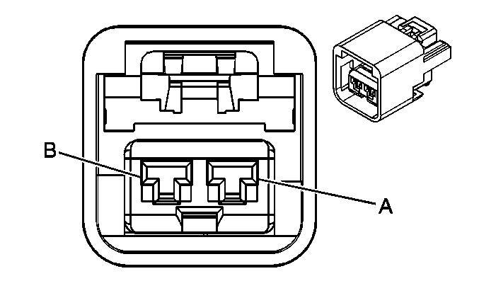
|
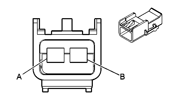
| ||||||||||||||
|---|---|---|---|---|---|---|---|---|---|---|---|---|---|---|---|
Connector Part Information |
| Connector Part Information |
| ||||||||||||
Pin | Wire Color | Circuit No. | Function | Pin | Wire Color | Circuit No. | Function | ||||||||
A | BK | 550 | Ground | A | BK | 550 | Ground | ||||||||
B | YE | 143 | Accessory Voltage | B | YE | 143 | Accessory Voltage | ||||||||
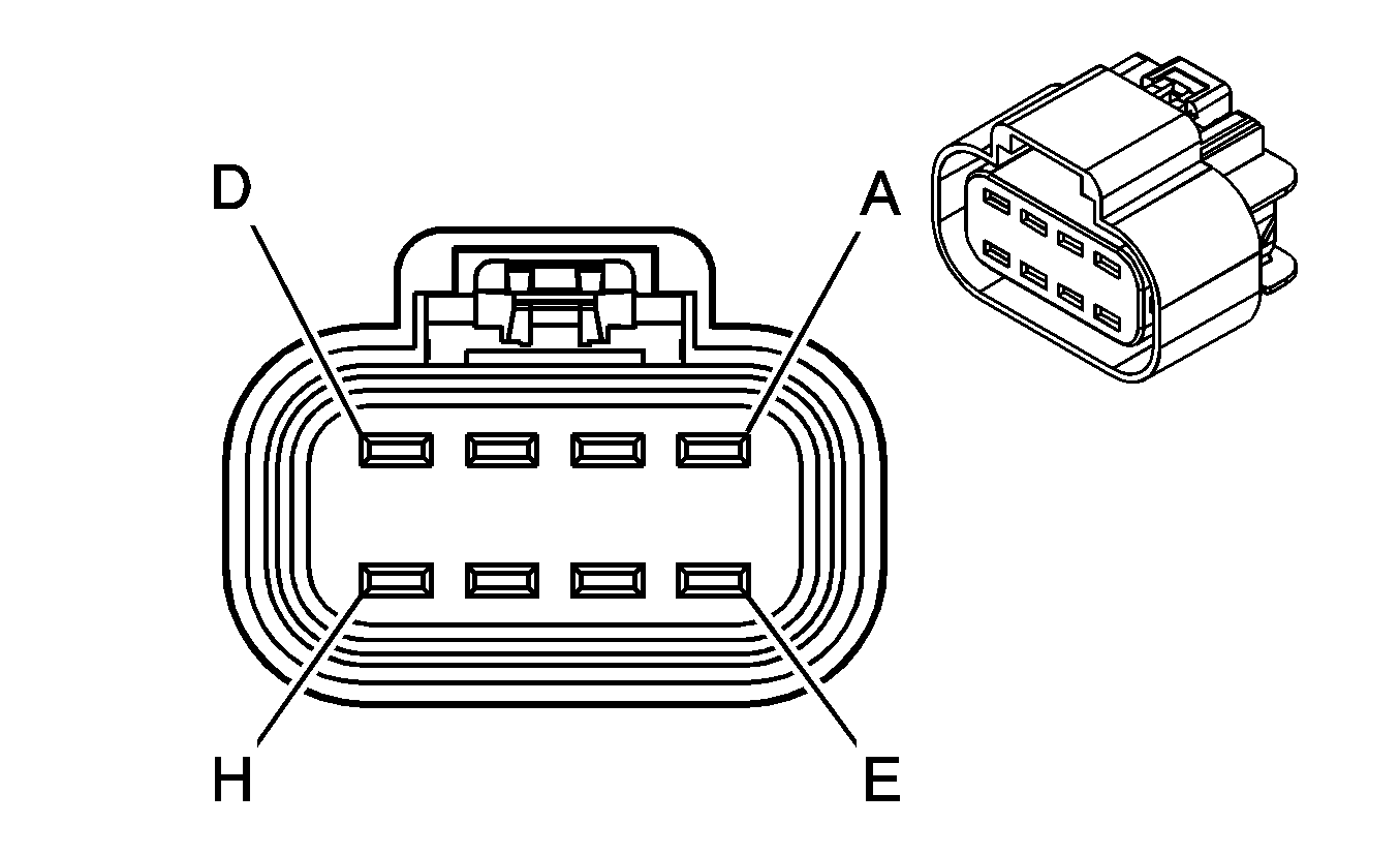
|
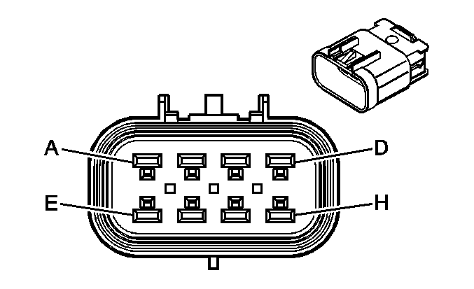
| ||||||||||||||
|---|---|---|---|---|---|---|---|---|---|---|---|---|---|---|---|
Connector Part Information |
| Connector Part Information |
| ||||||||||||
Pin | Wire Color | Circuit No. | Function | Pin | Wire Color | Circuit No. | Function | ||||||||
A | ORN | 840 | Battery Positive Voltage | A | -- | -- | Battery Positive Voltage | ||||||||
B | ORN | 840 | Battery Positive Voltage | B | -- | -- | Battery Positive Voltage | ||||||||
C | WHT | 320 | Ground | C | -- | -- | Ground | ||||||||
D | YEL | 321 | ALC Compressor Relay Control | D | -- | -- | ALC Compressor Relay Control | ||||||||
E | ORN | 1240 | Battery Positive Voltage | E | -- | -- | Battery Positive Voltage | ||||||||
F | ORN | 840 | Battery Positive Voltage | F | -- | -- | Battery Positive Voltage | ||||||||
G | BLK | 450 | Ground | G | -- | -- | Ground | ||||||||
H | WHT | 837 | ALC Inflator Relay Coil Control | H | -- | -- | ALC Inflator Relay Coil Control | ||||||||
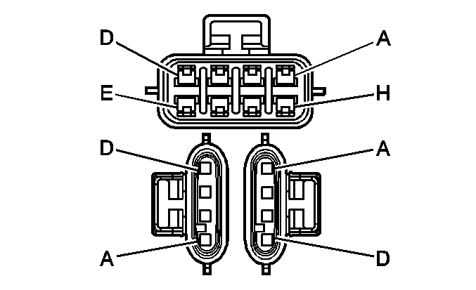
|
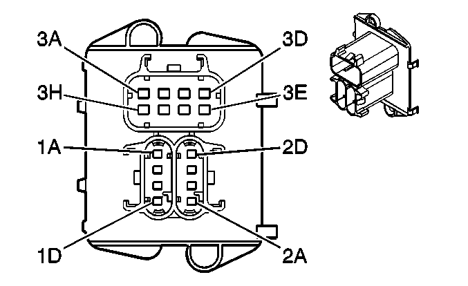
| ||||||||||||||||||||||
|---|---|---|---|---|---|---|---|---|---|---|---|---|---|---|---|---|---|---|---|---|---|---|---|
Connector Part Information |
| Connector Part Information |
| ||||||||||||||||||||
Pin | Wire Color | Circuit No. | Function | Pin | Wire Color | Circuit No. | Function | ||||||||||||||||
A | BN | 882 | Right Rear Wheel Speed Sensor Signal (JM4/JL9) | 1A | BN | 882 | Right Rear Wheel Speed Sensor Signal (JM4/JL9) | ||||||||||||||||
B | WH | 883 | Right Rear Wheel Speed Sensor Low Reference (JM4/JL9) | 1B | WH | 883 | Right Rear Wheel Speed Sensor Low Reference (JM4/JL9) | ||||||||||||||||
C | BK | 884 | Left Rear Wheel Speed Sensor Signal (JM4/JL9) | 1C | BK | 884 | Left Rear Wheel Speed Sensor Signal (JM4/JL9) | ||||||||||||||||
D | RD | 885 | Left Rear Wheel Speed Sensor Low Reference (JM4/JL9) | 1D | RD | 885 | Left Rear Wheel Speed Sensor Low Reference (JM4/JL9) | ||||||||||||||||
A | L-BU | 1296 | Axle Actuator - Control (AWD&JM4/JL9) | 2A | L-BU | 1296 | Axle Actuator - Control (AWD&JM4/JL9) | ||||||||||||||||
B | PK | 1439 | Ignition 1 Voltage | 2B | PK | 1439 | Ignition 1 Voltage | ||||||||||||||||
C | BK | 550 | Ground (JM4/JL9) | 2C | BK | 550 | Ground (JM4/JL9) | ||||||||||||||||
D | -- | -- | Not Used (JM4/JL9) | 2D | -- | -- | Not Used (JM4/JL9) | ||||||||||||||||
A | BK | 250 | Ground | 3A | BK | 250 | Ground | ||||||||||||||||
B | BK/WH | 2759 | Low Reference | 3B | BK | 2759 | Low Reference | ||||||||||||||||
C | GY | 120 | Fuel Pump Supply Voltage | 3C | GY | 120 | Fuel Pump Supply Voltage | ||||||||||||||||
D | PU | 1589 | Fuel Level Sensor Signal | 3D | PU/WH | 1589 | Fuel Level Sensor Signal | ||||||||||||||||
E | D-GN | 890 | Fuel Tank Pressure Sensor Signal | 3E | D-GN | 890 | Fuel Tank Pressure Sensor Signal | ||||||||||||||||
F | WH | 1310 | EVAP Canister Vent Solenoid Control | 3F | WH | 1310 | EVAP Canister Vent Solenoid Control | ||||||||||||||||
G | PK | 1239 | Ignition 1 Voltage | 3G | PK | 1239 | Ignition 1 Voltage | ||||||||||||||||
H | GY/BK | 2709 | 5-Volt Reference | 3H | GY | 2709 | 5-Volt Reference | ||||||||||||||||
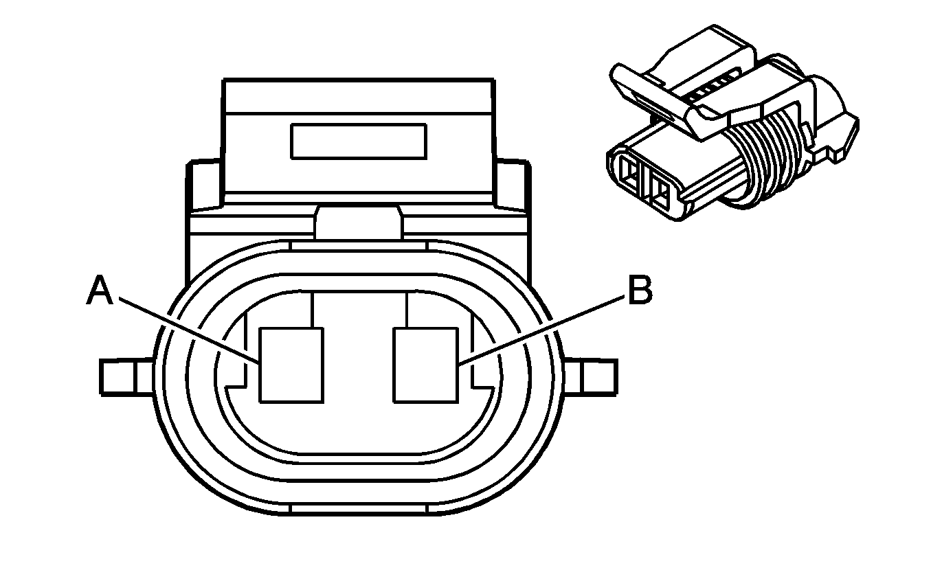
|
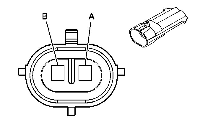
| ||||||||||||||
|---|---|---|---|---|---|---|---|---|---|---|---|---|---|---|---|
Connector Part Information |
| Connector Part Information |
| ||||||||||||
Pin | Wire Color | Circuit No. | Function | Pin | Wire Color | Circuit No. | Function | ||||||||
A | WH | 883 | Right Rear Wheel Speed Sensor Low Reference | A | WH | 883 | Right Rear Wheel Speed Sensor Low Reference | ||||||||
B | BK | 882 | Right Rear Wheel Speed Sensor Signal | B | BN | 882 | Right Rear Wheel Speed Sensor Signal | ||||||||

|

| ||||||||||||||
|---|---|---|---|---|---|---|---|---|---|---|---|---|---|---|---|
Connector Part Information |
| Connector Part Information |
| ||||||||||||
Pin | Wire Color | Circuit No. | Function | Pin | Wire Color | Circuit No. | Function | ||||||||
A1-A2 | -- | -- | Not Used | A1-A2 | -- | -- | Not Used | ||||||||
A3 | BARE | 814 | Drain Wire (U32) | A3 | BARE | 814 | Drain Wire (U32) | ||||||||
A4 | OG | 4240 | Battery Positive Voltage (U32) | A4 | OG | 4240 | Battery Positive Voltage (U32) | ||||||||
A5 | BK/WH | 351 | Ground (U32) | A5 | BK/WH | 351 | Ground (U32) | ||||||||
A6 | PK | 1045 | Ignition 3 Voltage (U32) | A6 | PK | 1045 | Ignition 3 Voltage (U32) | ||||||||
A7 | BK/WH | 367 | Remote Radio Left Audio Signal (U32) | A7 | BK/WH | 367 | Remote Radio Left Audio Signal (U32) | ||||||||
A8 | D-GN/WH | 368 | Remote Radio Right Audio Signal (U32) | A8 | D-GN/WH | 368 | Remote Radio Right Audio Signal (U32) | ||||||||
A9 | D-GN | 1927 | Rear Defog Element Supply Voltage | A9 | D-GN | 1927 | Rear Defog Element Supply Voltage | ||||||||
A10 | -- | -- | Not Used | A10 | -- | -- | Not Used | ||||||||
A11 | WH | 17 | Stop Lamp Switch Signal | A11 | WH | 17 | Stop Lamp Switch Signal | ||||||||
A12 | BARE | 1705 | Drain Wire (UE1) | A12 | BARE | 1705 | Drain Wire (UE1) | ||||||||
A13 | GY | 655 | Cellular Microphone Signal (UE1) | A13 | GY | 655 | Cellular Microphone Signal (UE1) | ||||||||
A14 | D-GN/WH | 2514 | Keypad Signal (UE1) | A14 | D-GN/WH | 2514 | Keypad Signal (UE1) | ||||||||
A15 | L-GN/BK | 2515 | Keypad Supply Voltage (UE1) | A15 | L-GN/BK | 2515 | Keypad Supply Voltage (UE1) | ||||||||
B1-B2 | -- | -- | Not Used | B1-B2 | -- | -- | Not Used | ||||||||
B3 | BK/WH | 372 | Remote Radio Audio Output (-) (U32) | B3 | BK/WH | 372 | Remote Radio Audio Output (-) (U32) | ||||||||
B4 | OG | 1732 | Courtesy Lamps Supply Voltage | B4 | OG | 1732 | Courtesy Lamps Supply Voltage | ||||||||
B5 | -- | -- | Not Used | B5 | -- | -- | Not Used | ||||||||
B6 | GY/BK | 690 | Courtesy Lamp Low Control | B6 | GY/BK | 690 | Courtesy Lamp Low Control | ||||||||
B7 | L-BU | 115 | Right Rear Speaker Output (-) (w/o UQ3) | B7-B8 | -- | -- | Not Used | ||||||||
B8 | -- | -- | Not Used | ||||||||||||
B9 | YE | 643 | Accessory Voltage (CF5) | B9 | YE | 643 | Accessory Voltage (CF5) | ||||||||
B10 | YE | 116 | Left Rear Speaker Output (-) (w/o UQ3) | B10 | YE | 116 | Left Rear Speaker Output (-) (w/o UQ3) | ||||||||
B11 | BN | 199 | Left Rear Speaker Output (+) (w/o UQ3) | B11 | BN | 199 | Left Rear Speaker Output (+) (w/o UQ3) | ||||||||
B12 | YE/BK | 2516 | Keypad Green LED Signal (UE1) | B12 | YE/BK | 2516 | Keypad Green LED Signal (UE1) | ||||||||
B13 | OG/BK | 2518 | Keypad Low Reference (UE1) | B13 | OG/BK | 2518 | Keypad Low Reference (UE1) | ||||||||
B14 | BN/WH | 2517 | Keypad Red LED Signal (UE1) | B14 | BN/WH | 2517 | Keypad Red LED Signal (UE1) | ||||||||
B15 | -- | -- | Not Used | B15 | -- | -- | Not Used | ||||||||

|

| ||||||||||||||
|---|---|---|---|---|---|---|---|---|---|---|---|---|---|---|---|
Connector Part Information |
| Connector Part Information |
| ||||||||||||
Pin | Wire Color | Circuit No. | Function | Pin | Wire Color | Circuit No. | Function | ||||||||
A | WH | 883 | Left Rear Wheel Speed Sensor Low Reference | A | RD | 885 | Left Rear Wheel Speed Sensor Low Reference | ||||||||
B | BK | 882 | Left Rear Wheel Speed Sensor Signal | B | BK | 884 | Left Rear Wheel Speed Sensor Signal | ||||||||

|

| ||||||||||||||
|---|---|---|---|---|---|---|---|---|---|---|---|---|---|---|---|
Connector Part Information |
| Connector Part Information |
| ||||||||||||
Pin | Wire Color | Circuit No. | Function | Pin | Wire Color | Circuit No. | Function | ||||||||
A1 | WH | 2370 | Telltale Assembly Supply Voltage | A1 | WH | 2370 | Telltale Assembly Supply Voltage | ||||||||
A2 | OG | 2371 | Left Amber Indicator Control | A2 | OG | 2371 | Left Amber Indicator Control | ||||||||
A3 | OG | 640 | Battery Positive Voltage | A3 | OG | 640 | Battery Positive Voltage | ||||||||
A4 | D-GN | 2308 | Passenger Air Bag Off Indicator Control (AL0) | A4 | D-GN | 2308 | Passenger Air Bag Off Indicator Control (AL0) | ||||||||
A5 | D-BU | 2307 | Passenger Air Bag On Indicator Control (AL0) | A5 | D-BU | 2307 | Passenger Air Bag On Indicator Control (AL0) | ||||||||
A6-A8 | -- | -- | Not Used | A6-A8 | -- | -- | Not Used | ||||||||
A9 | BK | 650 | Ground | A9 | BK | 650 | Ground | ||||||||
A10 | GY | 8 | Instrument Panel Lamp Supply Voltage | A10 | GY | 8 | Instrument Panel Lamp Supply Voltage | ||||||||
A11 | BARE | 1705 | Drain Wire | A11 | BARE | 1705 | Drain Wire | ||||||||
A12 | GY | 655 | Cellular Microphone Signal | A12 | GY | 655 | Cellular Microphone Signal | ||||||||
A13 | D-BU | 2372 | Center Amber Indicator Control | A13 | D-BU | 2372 | Center Amber Indicator Control | ||||||||
A14 | GY | 2373 | Red Indicator Control | A14 | GY | 2373 | Red Indicator Control | ||||||||
A15 | BARE | 814 | Drain Wire | A15 | BARE | 814 | Drain Wire | ||||||||
B1 | OG | 4240 | Battery Positive Voltage | B1 | OG | 4240 | Battery Positive Voltage | ||||||||
B2 | BK/WH | 351 | Ground | B2 | BK/WH | 351 | Ground | ||||||||
B3 | PK | 1045 | RFA Class 2 Serial Data | B3 | PK | 1045 | RFA Class 2 Serial Data | ||||||||
B4 | BN/WH | 367 | Remote Radio Left Audio Signal | B4 | BN/WH | 367 | Remote Radio Left Audio Signal | ||||||||
B5 | GN/WH | 368 | Remote Radio Right Audio Signal | B5 | GN/WH | 368 | Remote Radio Right Audio Signal | ||||||||
B6 | BK/WH | 372 | Remote Radio Audio Output (-) | B6 | BK/WH | 372 | Remote Radio Audio Output (-) | ||||||||
B7 | OG | 1732 | Courtesy Lamps Supply Voltage | B7 | OG | 1732 | Courtesy Lamps Supply Voltage | ||||||||
B8 | PK | 1239 | Ignition 1 Voltage | B8 | PK | 1239 | Ignition 1 Voltage | ||||||||
B9 | GY/BK | 690 | Courtesy Lamp Supply Voltage | B9 | GY/BK | 690 | Courtesy Lamp Supply Voltage | ||||||||
B10 | D-GN/WH | 2514 | Keypad Signal | B10 | D-GN/WH | 2514 | Keypad Signal | ||||||||
B11 | L-GN/BK | 2515 | Key Pad Supply Voltage | B11 | L-GN/BK | 2515 | Key Pad Supply Voltage | ||||||||
B12 | YE/BK | 2516 | Key Pad Green LED Signal | B12 | YE/BK | 2516 | Key Pad Green LED Signal | ||||||||
B13 | OG/BK | 2518 | Key Pad Low Reference | B13 | OG/BK | 2518 | Key Pad Low Reference | ||||||||
B14 | BN/WH | 2517 | Key Pad Red LED Signal | B14 | BN/WH | 2517 | Key Pad Red LED Signal | ||||||||
B15 | -- | -- | Not Used | B15 | -- | -- | Not Used | ||||||||
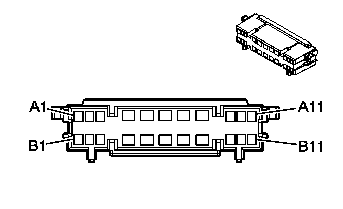
|
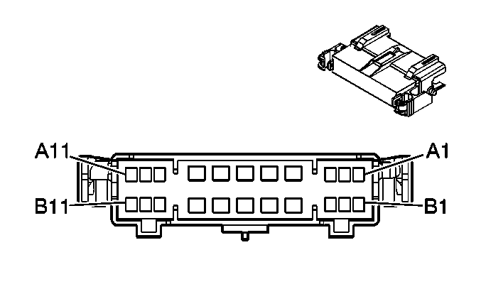
| ||||||||||||||
|---|---|---|---|---|---|---|---|---|---|---|---|---|---|---|---|
Connector Part Information |
| Connector Part Information |
| ||||||||||||
Pin | Wire Color | Circuit No. | Function | Pin | Wire Color | Circuit No. | Function | ||||||||
A1 | WH | 2370 | Telltale Assembly Supply Voltage | A1 | WH | 2370 | Telltale Assembly Supply Voltage | ||||||||
A2 | OG | 2371 | Left Amber Indicator Control | A2 | OG | 2371 | Left Amber Indicator Control | ||||||||
A3 | -- | -- | Not Used | A3 | -- | -- | Not Used | ||||||||
A4 | L-GN | 24 | Backup Lamp Supply Voltage | A4 | L-GN | 24 | Backup Lamp Supply Voltage | ||||||||
L-GN | 24 | Backup Lamp Supply Voltage | |||||||||||||
A5 | YE | 643 | Accessory Voltage | A5 | YE | 643 | Accessory Voltage | ||||||||
YE | 643 | Accessory Voltage | |||||||||||||
A6 | BK | 650 | Ground | A6 | BK | 650 | Ground | ||||||||
A7 | -- | -- | Not Used | A7 | -- | -- | Not Used | ||||||||
A8 | OG | 640 | Battery Positive Voltage | A8 | OG | 640 | Battery Positive Voltage | ||||||||
A9 | GY | 8 | Instrument Panel Lamp Supply Voltage | A9 | GY | 8 | Instrument Panel Lamp Supply Voltage | ||||||||
A10 | BARE | 1705 | Drain Wire | A10 | BARE | 1705 | Drain Wire | ||||||||
A11 | GY | 655 | Cellular Microphone Signal | A11 | GY | 655 | Cellular Microphone Signal | ||||||||
B1 | D-BU | 2372 | Center Amber Indicator Control | B1 | D-BU | 2372 | Center Amber Indicator Control | ||||||||
B2 | GY | 2373 | Red Indicator Control | B2 | GY | 2373 | Red Indicator Control | ||||||||
B3 | -- | -- | Not Used | B3 | -- | -- | Not Used | ||||||||
B4 | OG | 1732 | Courtesy Lamps Supply Voltage | B4 | OG | 1732 | Courtesy Lamps Supply Voltage | ||||||||
B5 | -- | -- | Not Used | B5 | -- | -- | Not Used | ||||||||
B6 | GY/BK | 690 | Courtesy Lamp Low Control | B6 | GY/BK | 690 | Courtesy Lamp Low Control | ||||||||
B7 | L-BU | 2514 | Key Pad Signal | B7 | L-BU | 2514 | Key Pad Signal | ||||||||
B8 | D-BU | 2515 | Key Pad Supply Voltage | B8 | D-BU | 2515 | Key Pad Supply Voltage | ||||||||
B9 | PU | 2516 | Key Pad Green LED Signal | B9 | PU | 2516 | Key Pad Green LED Signal | ||||||||
B10 | RD | 2518 | Key Pad Low Reference | B10 | RD | 2518 | Key Pad Low Reference | ||||||||
B11 | PK | 2517 | Key Pad Red LED Signal | B11 | PK | 2517 | Key Pad Red LED Signal | ||||||||
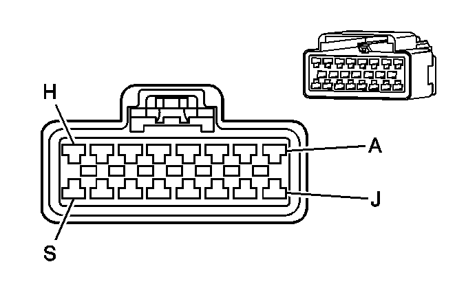
|
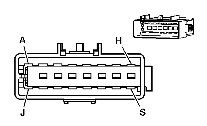
| ||||||||||||||
|---|---|---|---|---|---|---|---|---|---|---|---|---|---|---|---|
Connector Part Information |
| Connector Part Information |
| ||||||||||||
Pin | Wire Color | Circuit No. | Function | Pin | Wire Color | Circuit No. | Function | ||||||||
A | BK | 750 | Ground | A | BK | 750 | Ground | ||||||||
B | L-BU/BK | 1505 | Passenger Heated Seat Switch Signal | B | L-BU | 1505 | Passenger Heated Seat Switch Signa (KA1) | ||||||||
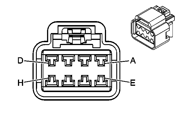
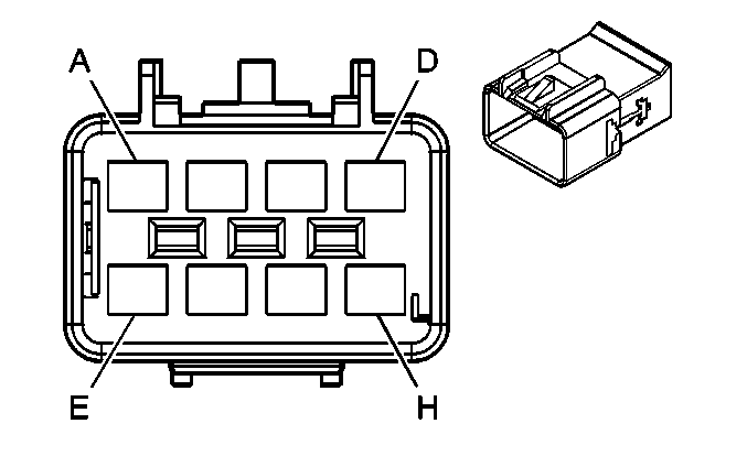
C | RD | 1362 | Seat Belt Switch - Right - Signal) | C | BK/WH | 1362 | Seat Belt Switch - Right - Signal | ||||||||
D | GY | 2488 | Passenger Seat Belt Tension Retractor Sensor -- Signal | D | PU | 2488 | Passenger Seat Belt Tension Retractor Sensor -- Signal | ||||||||
E | L-BU | 1361 | Seat Belt Switch - Right - Low Reference | E | TN | 1361 | Seat Belt Switch - Right - Low Reference | ||||||||
F | OG | 1140 | Battery Positive Voltage | F | OG | 1140 | Battery Positive Voltage (KA1) | ||||||||
G-H | -- | -- | Not Used | G-H | -- | -- | Not Used | ||||||||
J | BK/WH | 1751 | Ground | J | BK | 1751 | Ground | ||||||||
K | PK | 608 | 14-Volt Reference | K | L-BU | 608 | 14-Volt Reference | ||||||||
L | PK | 1539 | Ignition 1 Voltage | L | BK | 1539 | Ignition 1 Voltage | ||||||||
M | PK/WH | 5018 | Occupant Sensor - Serial Data | M | BK | 5018 | Occupant Sensor - Serial Data | ||||||||
N | -- | -- | Not Used | N | -- | -- | Not Used | ||||||||
P | D-GN | 2308 | Passenger Air Bag Off Indicator Control | P | BK | 2308 | Passenger Air Bag Off Indicator Control | ||||||||
R | -- | -- | Not Used | R | -- | -- | Not Used | ||||||||
S | D-BU | 2307 | Passenger Air Bag On Indicator Control | S | BK | 2307 | Passenger Air Bag On Indicator Control | ||||||||
|
| ||||||||||||||
|---|---|---|---|---|---|---|---|---|---|---|---|---|---|---|---|
Connector Part Information |
| Connector Part Information |
| ||||||||||||
Pin | Wire Color | Circuit No. | Function | Pin | Wire Color | Circuit No. | Function | ||||||||
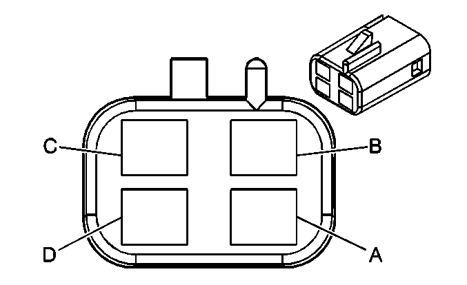
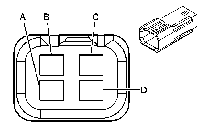
A | BK | 750 | Ground | A | BK | 750 | Ground | ||||||||
B | L-BU/BK | 1505 | Passenger Heated Seat Switch Signal | B | L-BU | 1505 | Passenger Heated Seat Switch Signal | ||||||||
C-E | -- | -- | Not Used | C-D | -- | -- | Not Used | ||||||||
E | TN/WH | 238 | Seat Belt Switch - Right | ||||||||||||
F | OG | 1140 | Battery Positive Voltage | F | OG | 1140 | Battery Positive Voltage | ||||||||
G-H | -- | -- | Not Used | G-H | -- | -- | Not Used | ||||||||
|
| ||||||||||||||
|---|---|---|---|---|---|---|---|---|---|---|---|---|---|---|---|
Connector Part Information |
| Connector Part Information |
| ||||||||||||
Pin | Wire Color | Circuit No. | Function | Pin | Wire Color | Circuit No. | Function | ||||||||
A | WH | -- | Heated Seat Switch Signal | A | L-BU | 1462 | Heated Seat Switch Signal | ||||||||
B | RD | -- | Battery Positive Voltage | B | OG | 1140 | Battery Positive Voltage | ||||||||
C | BK | -- | Ground | C | BK | 550 | Ground | ||||||||
D | -- | -- | Not Used | D | -- | -- | Not Used | ||||||||

|

| ||||||||||||||
|---|---|---|---|---|---|---|---|---|---|---|---|---|---|---|---|
Connector Part Information |
| Connector Part Information |
| ||||||||||||
Pin | Wire Color | Circuit No. | Function | Pin | Wire Color | Circuit No. | Function | ||||||||
A | WH | -- | Passenger Heated Seat Switch Signal | A | L-BU | 1505 | Passenger Heated Seat Switch Signal | ||||||||
B | RD | -- | Battery Positive Voltage | B | OG | 1140 | Battery Positive Voltage | ||||||||
C | BK | -- | Ground | C | BK | 750 | Ground | ||||||||
D | -- | -- | Not Used | D | -- | -- | Not Used | ||||||||

|

| ||||||||||||||
|---|---|---|---|---|---|---|---|---|---|---|---|---|---|---|---|
Connector Part Information |
| Connector Part Information |
| ||||||||||||
Pin | Wire Color | Circuit No. | Function | Pin | Wire Color | Circuit No. | Function | ||||||||
A1 | GY | 786 | Driver Mirror Horizontal Position Sensor Signal | A1 | GY | 786 | Driver Mirror Horizontal Position Sensor Signal | ||||||||
A2 | D-GN | 784 | Driver Mirror Vertical Position Sensor Signal | A2 | D-GN | 784 | Driver Mirror Vertical Position Sensor Signal | ||||||||
A3 | BN/WH | 1048 | SCM (Seat) Class 2 Serial Data | A3 | BN/WH | 1048 | SCM (Seat) Class 2 Serial Data | ||||||||
A4 | BN | 673 | Low Reference | A4 | BN | 673 | Low Reference | ||||||||
L-GN | 675 | Low Reference | |||||||||||||
A5 | -- | -- | Not Used | A5 | -- | -- | Not Used | ||||||||
A6 | RD/WH | 1513 | Passenger Mirror Switch Right Signal | A6 | RD/WH | 1513 | Passenger Mirror Switch Right Signal | ||||||||
A7 | WH | 1512 | Driver Mirror Switch Right Signal | A7 | WH | 1512 | Driver Mirror Switch Right Signal | ||||||||
A8 | GY | 915 | Mirror Switch Supply Voltage | A8 | TN | 915 | Mirror Switch Supply Voltage | ||||||||
A9 | L-GN | 89 | Driver Mirror Motor Down Control | A9 | D-GN | 89 | Driver Mirror Motor Down Control | ||||||||
A10 | L-BU | 82 | Driver Mirror Motor Left Control | A10 | L-BU | 82 | Driver Mirror Motor Left Control | ||||||||
A11 | WH | 81 | Driver Mirror Motor Right Control | A11 | WH | 81 | Driver Mirror Motor Right Control | ||||||||
B1 | L-BU/BK | 785 | Passenger Mirror Horizontal Position Sensor Signal | B1 | L-BU/BK | 785 | Passenger Mirror Horizontal Position Sensor Signal | ||||||||
B2 | BN | 787 | Passenger Mirror Vertical Position Sensor Signal | B2 | BN | 787 | Passenger Mirror Vertical Position Sensor Signal | ||||||||
B3 | PU/WH | 889 | Passenger Mirror Motor Down Control | B3 | PU/WH | 889 | Passenger Mirror Motor Down Control | ||||||||
B4 | -- | -- | Not Used | B4 | -- | -- | Not Used | ||||||||
B5 | PU/WH | 1515 | Passenger Mirror Switch Down Signal | B5 | PU/WH | 1515 | Passenger Mirror Switch Down Signal | ||||||||
B6 | YE | 1496 | Mirror Motor Left/Up Control | B6 | YE | 1496 | Mirror Motor Left/Up Control | ||||||||
B7 | -- | -- | Not Used | B7 | -- | -- | Not Used | ||||||||
B8 | D-BU | 672 | 5-Volt Reference | B8 | D-BU | 672 | 5-Volt Reference | ||||||||
YE | 674 | 5-Volt Reference | |||||||||||||
B9 | GY | 90 | Passenger Mirror Motor Left Control | B9 | GY | 90 | Passenger Mirror Motor Left Control | ||||||||
B10 | RD/WH | 881 | Passenger Mirror Motor Right Control | B10 | RD/WH | 881 | Passenger Mirror Motor Right Control | ||||||||
B11 | L-GN | 1514 | Driver Mirror Switch Down Control | B11 | D-GN | 1514 | Driver Mirror Switch Down Control | ||||||||
|
| ||||||||||||||
|---|---|---|---|---|---|---|---|---|---|---|---|---|---|---|---|
Connector Part Information |
| Connector Part Information |
| ||||||||||||
Pin | Wire Color | Circuit No. | Function | Pin | Wire Color | Circuit No. | Function | ||||||||
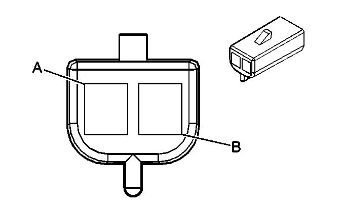
A | BN | Heated Seat Element (Back) - Driver Ground | A | BK | Heated Seat Element (Back) - Driver Ground | ||||||||||
B | BN | Heated Seat Element (Back) - Driver Supply Voltage | B | YE | Heated Seat Element (Back) - Driver Supply Voltage | ||||||||||

|

| ||||||||||||||
|---|---|---|---|---|---|---|---|---|---|---|---|---|---|---|---|
Connector Part Information |
| Connector Part Information |
| ||||||||||||
Pin | Wire Color | Circuit No. | Function | Pin | Wire Color | Circuit No. | Function | ||||||||
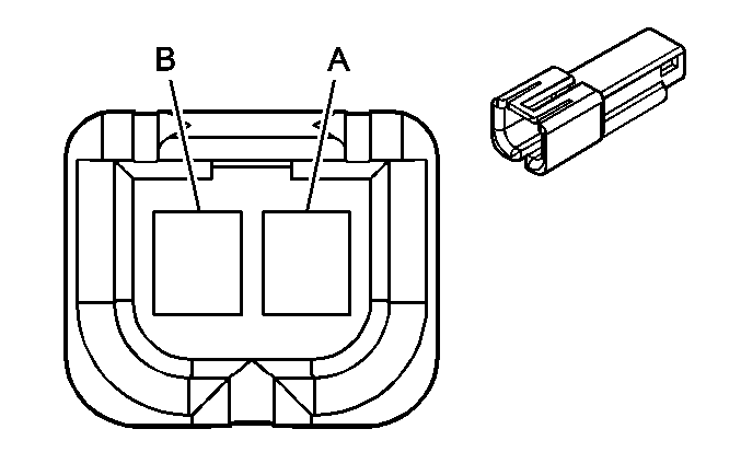
A | BN | Heated Seat Element (Back) - Front Passenger Ground | A | BK | Heated Seat Element (Back) - Front Passenger Ground | ||||||||||
B | BN | Heated Seat Element (Back) - Front Passenger Supply Voltage | B | YE | Heated Seat Element (Back) - Front Passenger Supply Voltage | ||||||||||
|
| ||||||||||||||||||
|---|---|---|---|---|---|---|---|---|---|---|---|---|---|---|---|---|---|---|---|
Connector Part Information |
| Connector Part Information |
| ||||||||||||||||
Pin | Wire Color | Circuit No. | Function | Pin | Wire Color | Circuit No. | Function | ||||||||||||
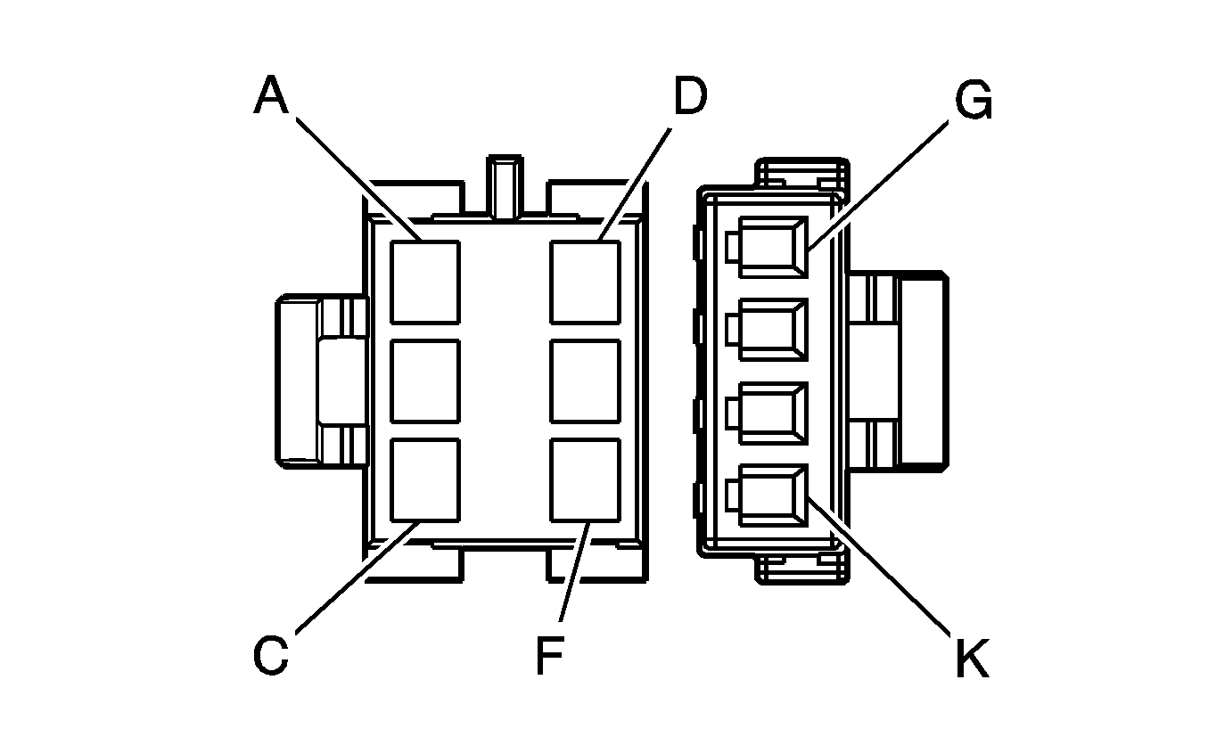
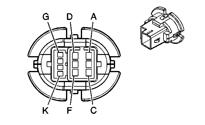
A | PU | 169 | Power Window Master Switch Left Rear Down Signal | A | PU | 169 | Power Window Master Switch Left Rear Down Signal | ||||||||||||
B | GY | 295 | Door Lock Actuator Lock Control | B | GY | 295 | Door Lock Actuator Lock Control | ||||||||||||
C | BK | 775 | Side Door Jamb Switch Signal | C | PK | 775 | Side Door Jamb Switch Signal | ||||||||||||
D | D-BU | 1307 | Power Window Master Switch Lockout Signal | D | D-BU | 1307 | Power Window Master Switch Lockout Signal | ||||||||||||
E | TN | 294 | Door Lock Actuator Unlock Control | E | TN | 294 | Door Lock Actuator Unlock Control | ||||||||||||
F | D-GN | 168 | Power Window Master Switch Left Rear Up Signal | F | D-GN | 168 | Power Window Master Switch Left Rear Up Signal | ||||||||||||
G | YE | 116 | Left Rear Speaker Output (-) | G | YE | 116 | Left Rear Speaker Output (-) | ||||||||||||
H | BK | 550 | Ground | H | BK | 550 | Ground | ||||||||||||
J | D-BU/WH | 727 | Door Ajar Switch Signal | J | D-BU/WH | 727 | Door Ajar Switch Signal | ||||||||||||
K | BN | 199 | Left Rear Speaker Output (+) | K | BN | 199 | Left Rear Speaker Output (+) | ||||||||||||

|

| ||||||||||||||||||
|---|---|---|---|---|---|---|---|---|---|---|---|---|---|---|---|---|---|---|---|
Connector Part Information |
| Connector Part Information |
| ||||||||||||||||
Pin | Wire Color | Circuit No. | Function | Pin | Wire Color | Circuit No. | Function | ||||||||||||
A | PU | 171 | Power Window Master Switch Right Rear Down Signal | A | PU | 171 | Power Window Master Switch Right Rear Down Signal | ||||||||||||
B | GY | 295 | Door Lock Actuator Lock Control | B | GY | 295 | Door Lock Actuator Lock Control | ||||||||||||
C | BK | 775 | Side Door Jamb Switch Signal | C | PK | 775 | Side Door Jamb Switch Signal | ||||||||||||
D | D-BU | 1307 | Power Window Master Switch Lockout Signal | D | D-BU | 1307 | Power Window Master Switch Lockout Signal | ||||||||||||
E | TN | 294 | Door Lock Actuator Unlock Control | E | TN | 294 | Door Lock Actuator Unlock Control | ||||||||||||
F | L-GN | 170 | Power Window Master Switch Right Rear Up Signal | F | L-GN | 170 | Power Window Master Switch Right Rear Up Signal | ||||||||||||
G | L-BU | 115 | Right Rear Speaker Output (-) | G | L-BU | 115 | Right Rear Speaker Output (-) | ||||||||||||
H | BK | 750 | Ground | H | BK | 750 | Ground | ||||||||||||
J | D-BU/WH | 727 | Door Ajar Switch Signal | J | D-BU/WH | 727 | Door Ajar Switch Signal | ||||||||||||
K | D-BU | 46 | Right Rear Speaker Output (+) | K | D-BU | 46 | Right Rear Speaker Output (+) | ||||||||||||
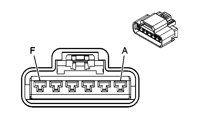
|

| ||||||||||||||
|---|---|---|---|---|---|---|---|---|---|---|---|---|---|---|---|
Connector Part Information |
| Connector Part Information |
| ||||||||||||
Pin | Wire Color | Circuit No. | Function | Pin | Wire Color | Circuit No. | Function | ||||||||
A | YE | 643 | Accessory Voltage | A | YE | 643 | Accessory Voltage | ||||||||
B | BK | 650 | Ground | B | BK | 650 | Ground (CF5) | ||||||||
C | BN | 100 | Sunroof Switch Open Signal | C | BN | 100 | Sunroof Switch Open Signal | ||||||||
D | D-BU | 128 | Sunroof Switch Low Reference | D | D-BU | 128 | Sunroof Switch Low Reference | ||||||||
E | OG | 110 | Sunroof Switch Close Signal | E | OG | 110 | Sunroof Switch Close Signal | ||||||||
F | -- | -- | Not Used | F | -- | -- | Not Used | ||||||||
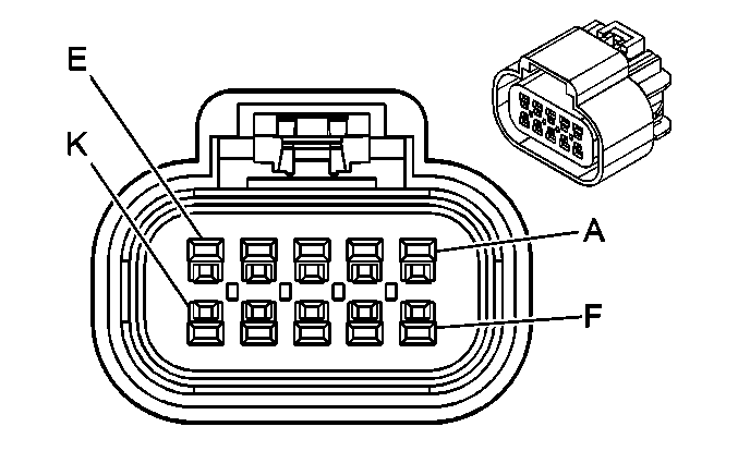
|
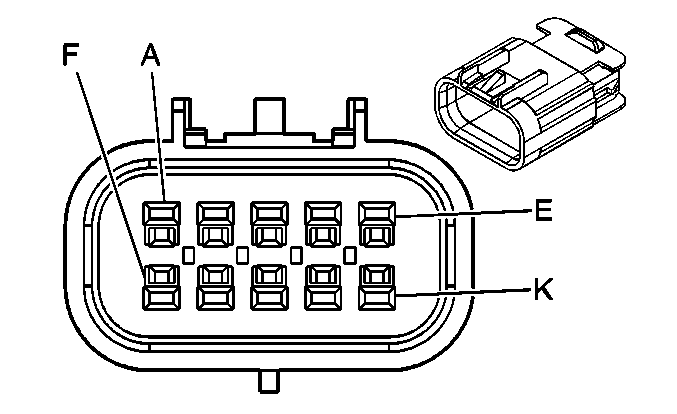
| ||||||||||||||
|---|---|---|---|---|---|---|---|---|---|---|---|---|---|---|---|
Connector Part Information |
| Connector Part Information |
| ||||||||||||
Pin | Wire Color | Circuit No. | Function | Pin | Wire Color | Circuit No. | Function | ||||||||
A | BN | 9 | Park Lamp Supply Voltage | A | BN | 9 | Park Lamp Supply Voltage | ||||||||
B | OG | 9294 | Endgate Lock Motor Unlock Control | B | OG | 9294 | Endgate Lock Motor Unlock Control | ||||||||
C | RD | 9295 | Endgate Lock Motor Lock Control | C | RD | 9295 | Endgate Lock Motor Lock Control | ||||||||
D | PK/BK | 1303 | Liftgate Ajar Switch Signal | D | PK/BK | 1303 | Liftgate Ajar Switch Signal | ||||||||
E | PU | 9124 | Liftgate Release Switch Signal | E | PU | 9124 | Liftgate Release Switch Signal | ||||||||
F | RD/BK | 744 | Trunk Ajar Switch Signal | F | RD/BK | 744 | Trunk Ajar Switch Signal | ||||||||
G | L-BU | 383 | Trunk Release Control | G | L-BU | 383 | Trunk Release Control | ||||||||
H | PU | 2279 | Lift Glass Ajar Switch Signal | H | PU | 2279 | Lift Glass Ajar Switch Signal | ||||||||
J | BK | 450 | Ground | J | BK | 450 | Ground | ||||||||
K | YE | 656 | Endgate Courtesy Lamp Control | K | YE | 656 | Endgate Courtesy Lamp Control | ||||||||

|

| ||||||||||||||
|---|---|---|---|---|---|---|---|---|---|---|---|---|---|---|---|
Connector Part Information |
| Connector Part Information |
| ||||||||||||
Pin | Wire Color | Circuit No. | Function | Pin | Wire Color | Circuit No. | Function | ||||||||
A | OG | 840 | Battery Positive Voltage | A | OG | 840 | Battery Positive Voltage | ||||||||
B | WH | 320 | Automatic Level Control Exhaust Solenoid Control | B | WH | 320 | Automatic Level Control Exhaust Solenoid Control | ||||||||
C | YE | 321 | Automatic Level Control Relay Control | C | YE | 321 | Automatic Level Control Relay Control | ||||||||
D | OG | 1240 | Battery Positive Voltage | D | OG | 1240 | Battery Positive Voltage | ||||||||
E | WH | 837 | Automatic Level Control Inflator Relay Coil Control | E | WH | 837 | Automatic Level Control Inflator Relay Coil Control | ||||||||
F | BK | 450 | Ground | F | BK | 450 | Ground | ||||||||
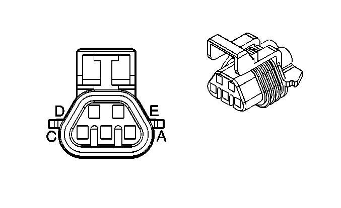
|
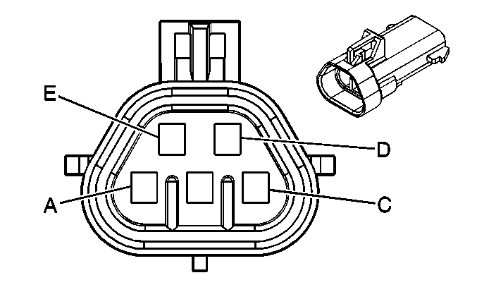
| ||||||||||||||
|---|---|---|---|---|---|---|---|---|---|---|---|---|---|---|---|
Connector Part Information |
| Connector Part Information |
| ||||||||||||
Pin | Wire Color | Circuit No. | Function | Pin | Wire Color | Circuit No. | Function | ||||||||
A | BN | 9 | Park Lamp Supply Voltage | A | BN | 9 | Park Lamp Supply Voltage | ||||||||
B | L-GN | 24 | Backup Lamp Supply Voltage (Pontiac) | B | L-GN | 24 | Backup Lamp Supply Voltage (Pontiac) | ||||||||
BN | 9 | Park Lamp Supply Voltage (Buick) | BN | 9 | Park Lamp Supply Voltage (Buick) | ||||||||||
C | YE | 18 | Left Rear Stop/Turn Lamp Supply Voltage | C | D-GN/YE | 18 | Left Rear Stop/Turn Lamp Supply Voltage | ||||||||
D | BK | 850 | Ground | D | BK | 850 | Ground | ||||||||
E | BK | 850 | Ground | E | BK | 850 | Ground | ||||||||

|

| ||||||||||||||
|---|---|---|---|---|---|---|---|---|---|---|---|---|---|---|---|
Connector Part Information |
| Connector Part Information |
| ||||||||||||
Pin | Wire Color | Circuit No. | Function | Pin | Wire Color | Circuit No. | Function | ||||||||
A | BN | 9 | Park Lamp Supply Voltage | A | BN | 9 | Park Lamp Supply Voltage | ||||||||
B | L-GN | 24 | Backup Lamp Supply Voltage (Pontiac) | B | L-GN | 24 | Backup Lamp Supply Voltage (Pontiac) | ||||||||
BN | 9 | Park Lamp Supply Voltage (Buick) | BN | 9 | Park Lamp Supply Voltage (Buick) | ||||||||||
C | D-GN | 19 | Right Rear Stop/Turn Lamp Supply Voltage | C | D-GN/YE | 19 | Right Rear Stop/Turn Lamp Supply Voltage | ||||||||
D | BK | 1850 | Ground | D | BK | 1850 | Ground | ||||||||
E | BK | 1850 | Ground | E | BK | 1850 | Ground | ||||||||

|

| ||||||||||||||
|---|---|---|---|---|---|---|---|---|---|---|---|---|---|---|---|
Connector Part Information |
| Connector Part Information |
| ||||||||||||
Pin | Wire Color | Circuit No. | Function | Pin | Wire Color | Circuit No. | Function | ||||||||
A | D-BU | 2374 | Object Sensor Supply Voltage | A | D-BU | 2374 | Object Sensor Supply Voltage | ||||||||
B | YE | 2375 | LR Corner Object Sensor Signal | B | YE | 2375 | LR Corner Object Sensor Signal | ||||||||
C | GY | 2379 | Object Sensor Low Reference | C | GY | 2379 | Object Sensor Low Reference | ||||||||
D | OG | 2376 | LR Middle Object Sensor Signal | D | OG | 2376 | LR Middle Object Sensor Signal | ||||||||
E | D-GN | 2377 | RR Middle Object Sensor Signal | E | D-GN | 2377 | RR Middle Object Sensor Signal | ||||||||
F | RD | 2378 | RR Corner Object Sensor Signal | F | RD | 2378 | RR Corner Object Sensor Signal | ||||||||

|

| ||||||||||||||
|---|---|---|---|---|---|---|---|---|---|---|---|---|---|---|---|
Connector Part Information |
| Connector Part Information |
| ||||||||||||
Pin | Wire Color | Circuit No. | Function | Pin | Wire Color | Circuit No. | Function | ||||||||
A | D-GN | 1927 | Rear Defog Element Supply Voltage | A | D-GN | 1927 | Rear Defog Element Supply Voltage | ||||||||
B | YE | 656 | Liftgate Courtesy Lamp Control | B | YE | 656 | Liftgate Courtesy Lamp Control | ||||||||
C | PK/BK | 1303 | Liftgate Ajar Switch Signal | C | PK/BK | 1303 | Liftgate Ajar Switch Signal | ||||||||
D | WH/BK | 1221 | Lift Gate Release Switch Signal | D | WH/BK | 1221 | Lift Gate Release Switch Signal | ||||||||
E | WH | 17 | Stop Lamp Switch Signal | E | WH | 17 | Stop Lamp Switch Signal | ||||||||
F | PU | 1305 | Liftgate Lock Motor Unlock Signal | F | PU | 1305 | Liftgate Lock Motor Unlock Signal | ||||||||
G | BN | 9 | Park Lamp Supply Voltage | G | BN | 9 | Park Lamp Supply Voltage | ||||||||
H | L-GN | 24 | Backup Lamp Supply Voltage | H | L-GN | 24 | Backup Lamp Supply Voltage | ||||||||
L-GN | 24 | Backup Lamp Supply Voltage | |||||||||||||
J | WH | 1304 | Liftgate Lock Motor Lock Control | J | WH | 1304 | Liftgate Lock Motor Lock Control | ||||||||
K | -- | -- | Not Used | K | -- | -- | Not Used | ||||||||
L | YE | 343 | Accessory Voltage | L | YE | 343 | Accessory Voltage | ||||||||
M | GY | 391 | Rear Window Wiper Switch Signal | M | GY | 391 | Rear Window Wiper Switch Signal | ||||||||
N | D-GN | 392 | Rear Window Washer Pump Control | N | D-GN | 392 | Rear Window Washer Pump Control | ||||||||
P | BK | 1150 | Ground | P | BK | 1150 | Ground | ||||||||
R-S | -- | -- | Not Used | R-S | -- | -- | Not Used | ||||||||

|

| ||||||||||||||
|---|---|---|---|---|---|---|---|---|---|---|---|---|---|---|---|
Connector Part Information |
| Connector Part Information |
| ||||||||||||
Pin | Wire Color | Circuit No. | Function | Pin | Wire Color | Circuit No. | Function | ||||||||
A | BK | 450 | Ground | A | -- | -- | Ground | ||||||||
B | BN | 9 | Park Lamp Supply Voltage | B | -- | -- | Park Lamp Supply Voltage | ||||||||
C | OG | 2540 | Battery Positive Voltage | C | -- | -- | Battery Positive Voltage | ||||||||
D | YE | 18 | Left Rear Stop/Turn Lamp Supply Voltage | D | -- | -- | Left Rear Stop/Turn Lamp Supply Voltage | ||||||||
E | D-GN | 19 | Right Rear Stop/Turn Lamp Supply Voltage | E | -- | -- | Right Rear Stop/Turn Lamp Supply Voltage | ||||||||

|

| ||||||||||||||
|---|---|---|---|---|---|---|---|---|---|---|---|---|---|---|---|
Connector Part Information |
| Connector Part Information |
| ||||||||||||
Pin | Wire Color | Circuit No. | Function | Pin | Wire Color | Circuit No. | Function | ||||||||
A | BN | 9 | Park Lamp Supply Voltage | A | L-GN | -- | Ground | ||||||||
B | L-GN | 24 | Backup Lamp Supply Voltage | B | WH | -- | Park Lamp Supply Voltage | ||||||||
C | -- | -- | Not Used | C | -- | -- | Not Used | ||||||||
D | L-GN | 24 | Backup Lamp Supply Voltage | D | BN | -- | Left Rear Stop/Turn Lamp Supply Voltage | ||||||||
E | BK | 1150 | Ground | E | BK | -- | Right Rear Stop/Turn Lamp Supply Voltage | ||||||||
