Tools Required
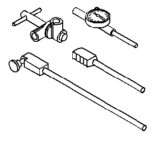
J 8520 Camshaft Lobe
Lift Indicator
Inspect the following areas:
| • |
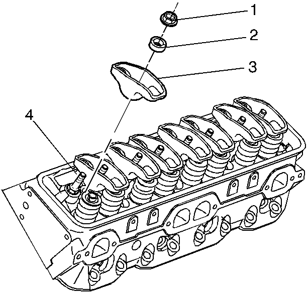
Inspect the valve rocker arms and ball at the mating surfaces. These
surfaces should be smooth and free of scoring or other damage. |
| • | Inspect the valve rocker arm valve pushrod sockets and valve stem
mating surfaces. These surfaces should be smooth with no scoring or exceptional
wear. |
| • |
Inspect the valve pushrods for scored ends or bends. |
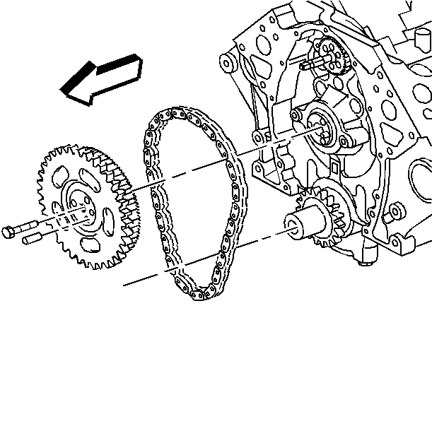
| • | The camshaft and crankshaft sprockets and water pump driveshaft
for wear |
| • | One edge of worn teeth or that are no longer concentric |
| • | The valley between worn teeth |
| • | The key and crankshaft keyway for wear |
| • | The crankshaft timing chain for binding |
| • |
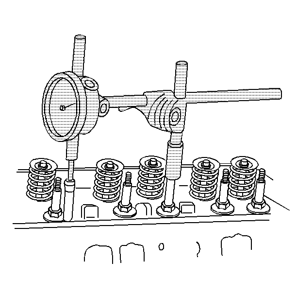
Measure the camshaft lobe lift. |
| 0.1. | Position the J 8520
with the ball socket adapter on the valve pushrod. Be sure that the
valve pushrod is in the valve lifter socket. |
| 0.2. | Slowly rotate the crankshaft until the valve lifter roller is
on the heel of the cam lobe. The valve pushrod will be in its lowest position. |
| 0.4. | Slowly rotate the crankshaft until the valve pushrod is raised
fully. |
| 0.5. | Compare the total lift shown on the J 8520
with the specifications. |
