For 1990-2009 cars only
Removal Procedure
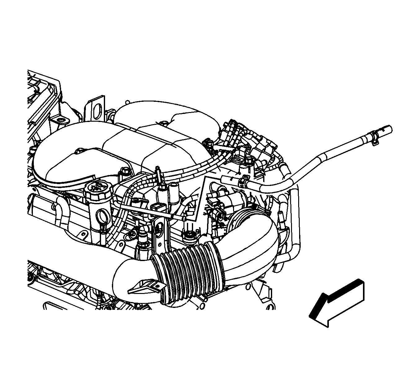
- Remove the intake manifold cover. Refer to Intake Manifold Cover Replacement .
- Relieve the fuel system pressure. Refer to Fuel Pressure Relief .
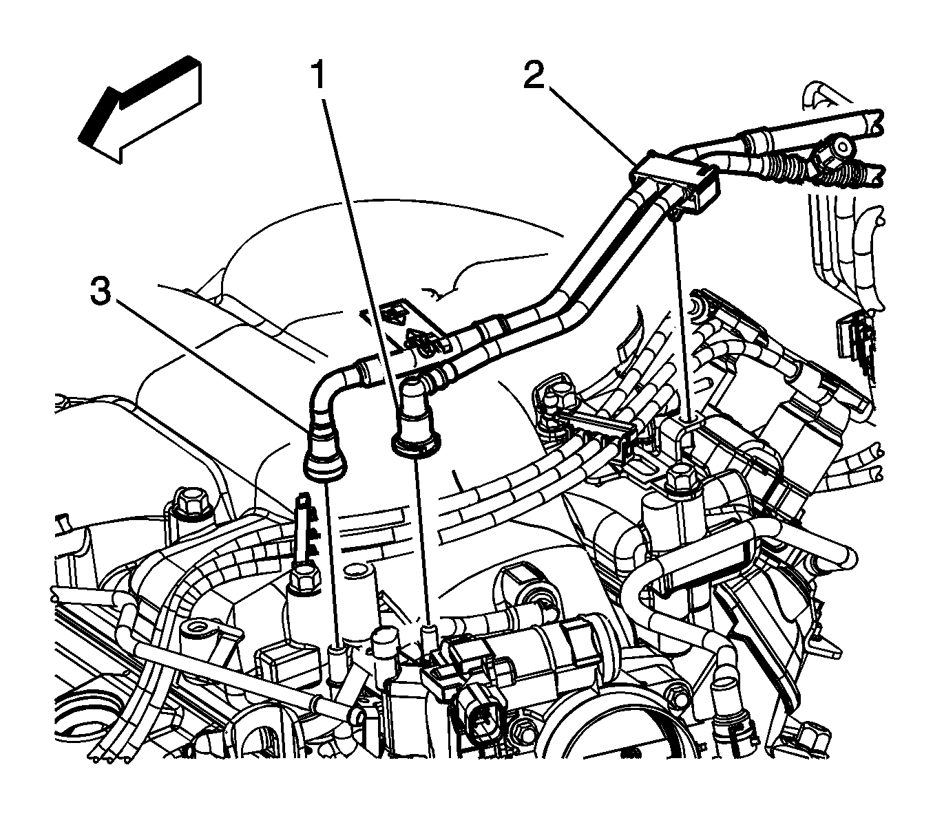
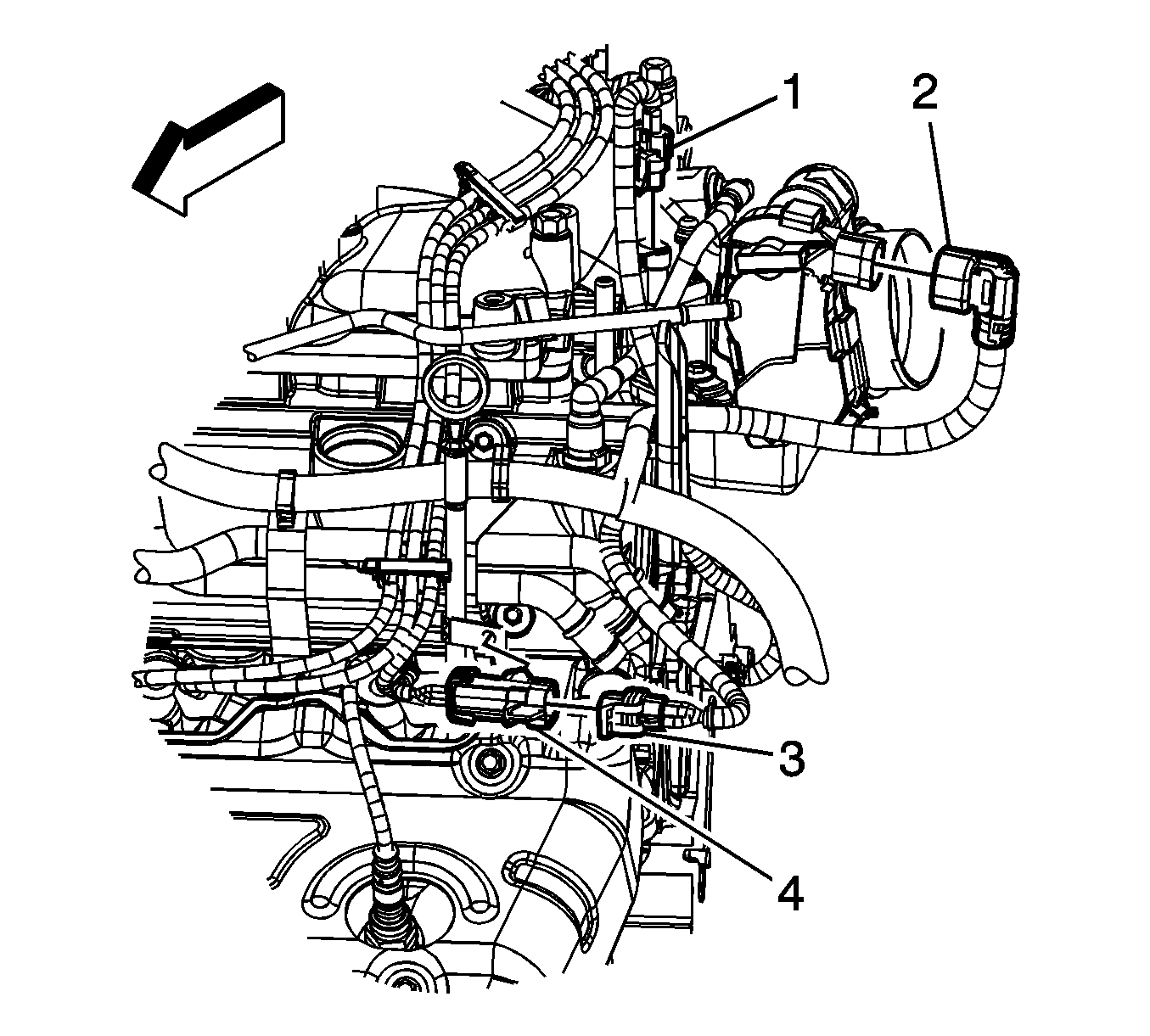
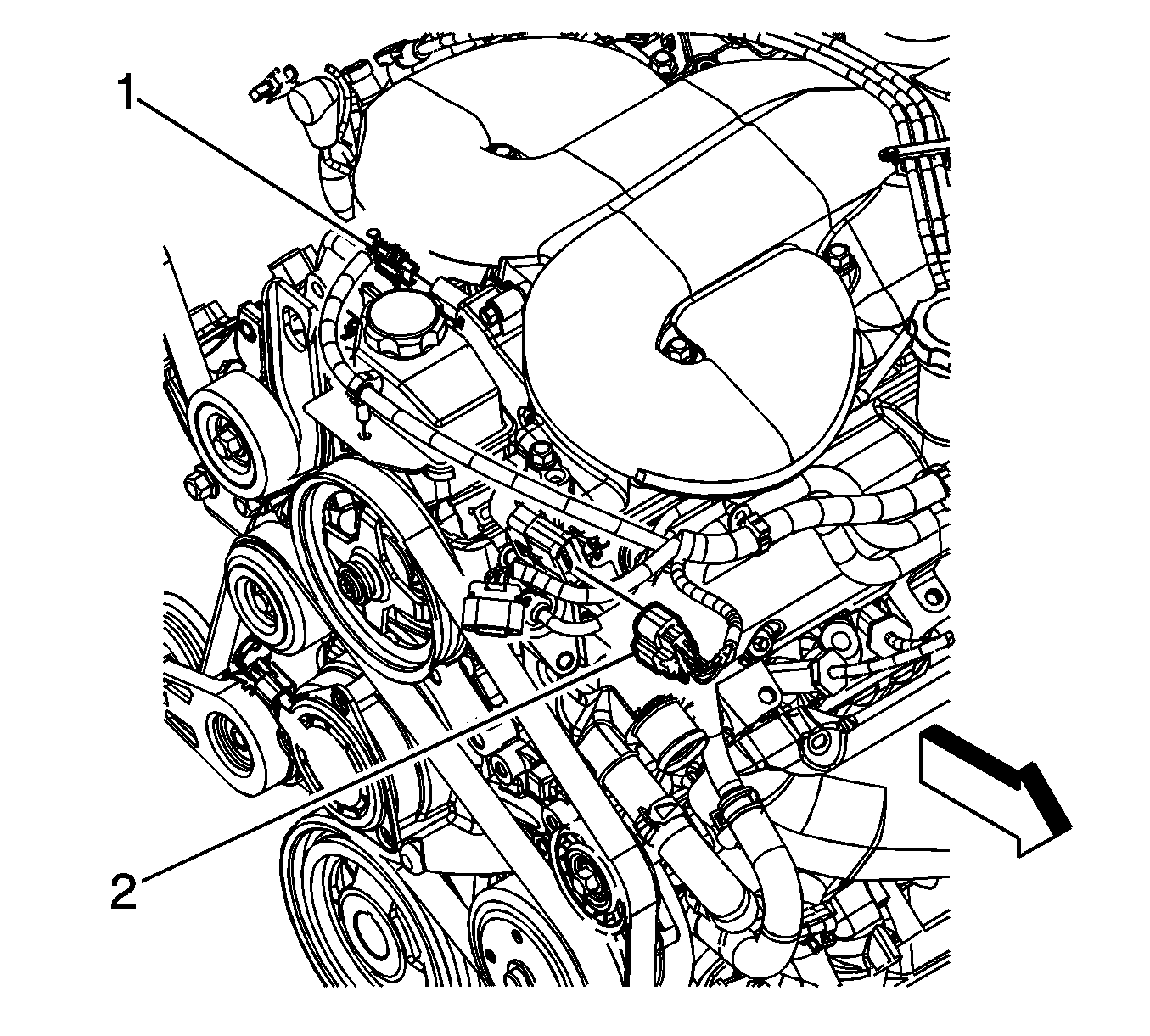
- Disconnect the fuel feed pipe (3) quick connect fitting from the fuel rail. Refer to Metal Collar Quick Connect Fitting Service .
- Disconnect the evaporative (EVAP) emission pipe (1) from the purge solenoid. Refer to Plastic Collar Quick Connect Fitting Service .
- Open the retaining clip (2), and remove the fuel and EVAP pipes from the clip.
- Drain the cooling system. Refer to Cooling System Draining and Filling .
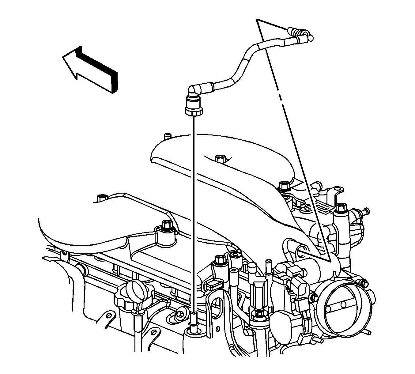
- Remove the positive crankcase ventilation (PCV) fresh air tube. Refer to Plastic Collar Quick Connect Fitting Service .
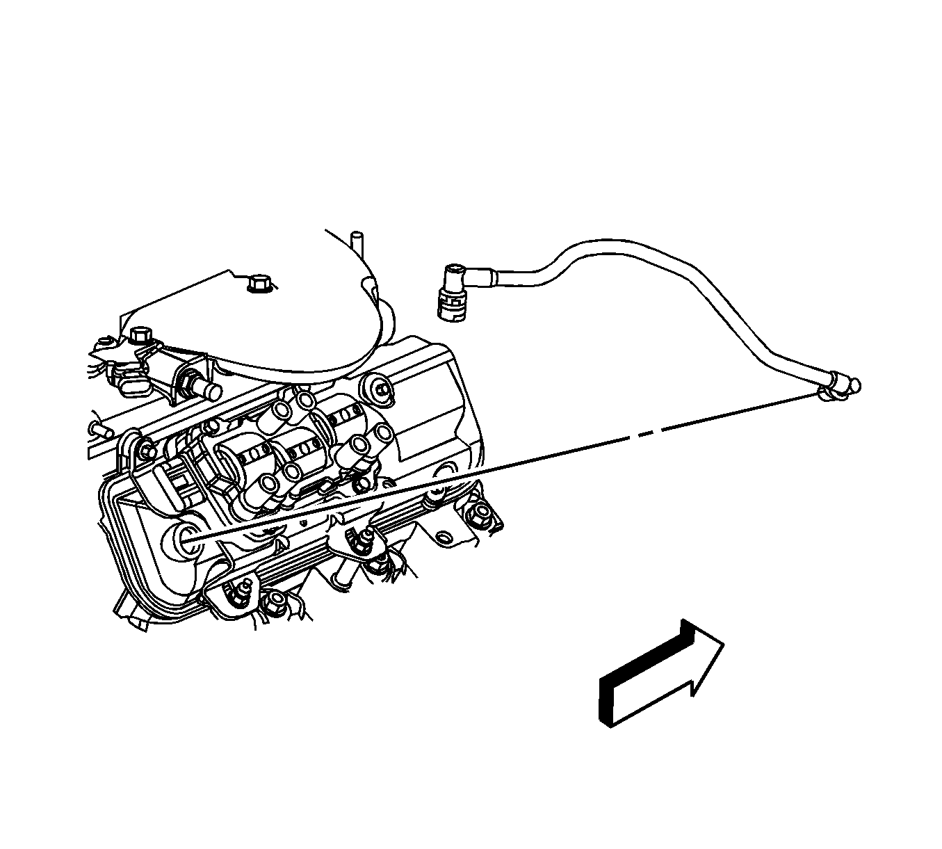
- Remove the PCV foul air tube. Refer to Plastic Collar Quick Connect Fitting Service .
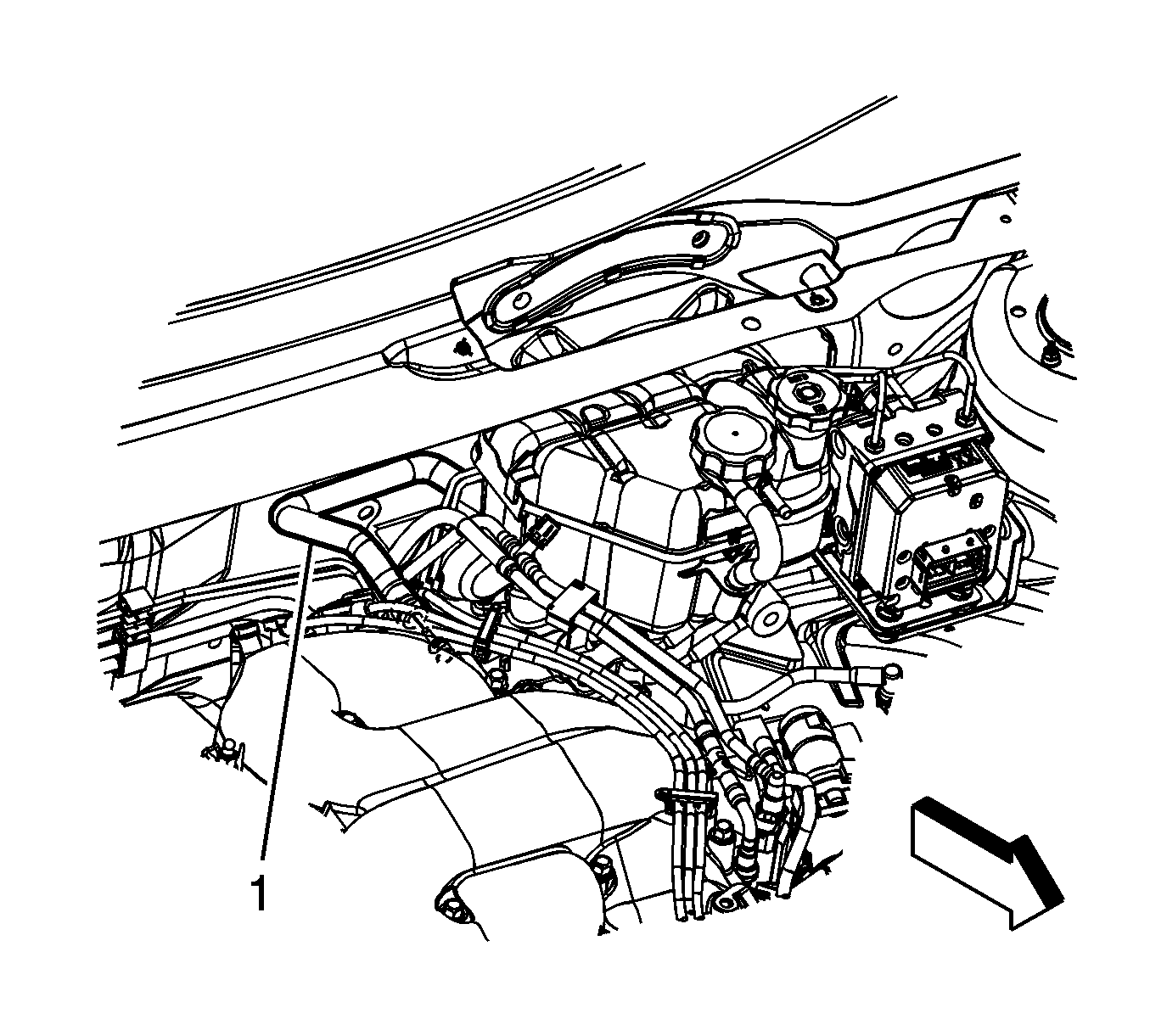
- Reposition the brake booster vacuum hose clamp at the intake manifold.
- Remove the vacuum hose (1) from the intake manifold.
- Reposition the radiator surge tank inlet hose clamp.
- Remove the radiator surge tank inlet hose from the inlet pipe.
- Remove the radiator surge tank inlet pipe bolts.
- Remove the radiator surge tank inlet pipe.
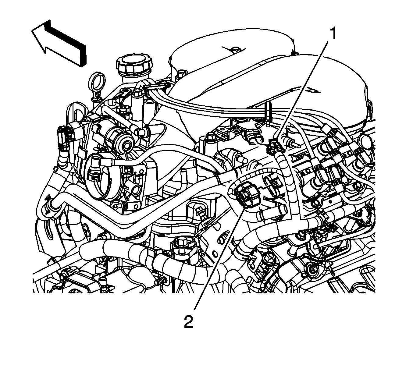
- Disconnect the manifold absolute pressure (MAP) sensor electrical connector (1).
- Disconnect the evaporative emission (EVAP) canister purge solenoid electrical connector (1).
- Disconnect the electronic throttle control (ETC) electrical connector (2).
- Disconnect the inlet manifold valve electrical connector (1).
- Remove the air cleaner outlet duct. Refer to Air Cleaner Outlet Duct Replacement .
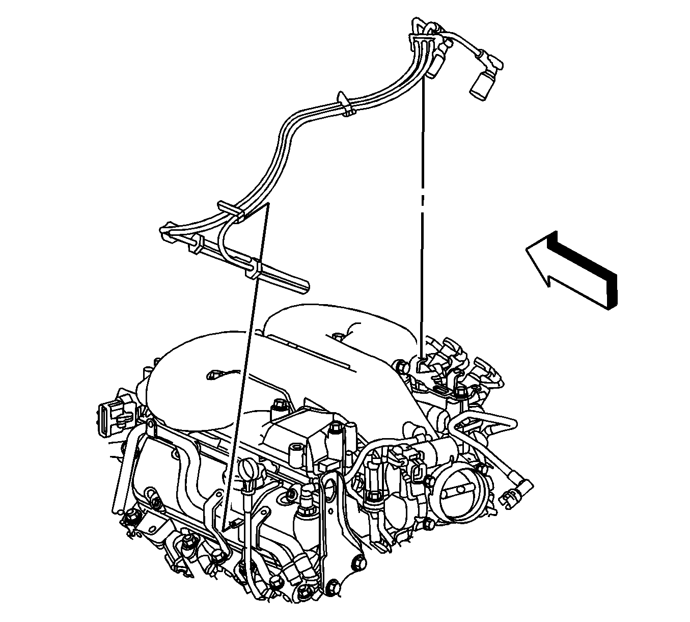
- Disconnect the left side spark plug wires from the spark plugs.
- Disconnect the left side spark plug wires from the ignition coil.
- Disengage the spark plug wire retainer clips from the intake manifold bracket and the heater inlet/outlet pipe.
- Remove the left side spark plug wires.
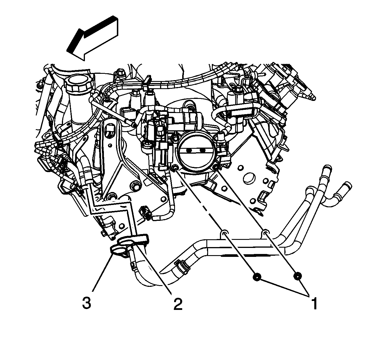
- Remove the heater inlet and outlet pipe nuts (1) from the throttle body studs.
- Remove the inlet and outlet pipe (2, 3) from the studs.
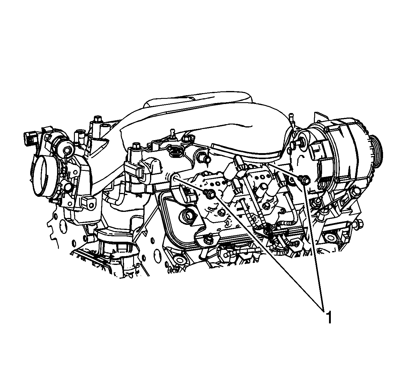
- Remove the 2 ignition coil bolts (1).
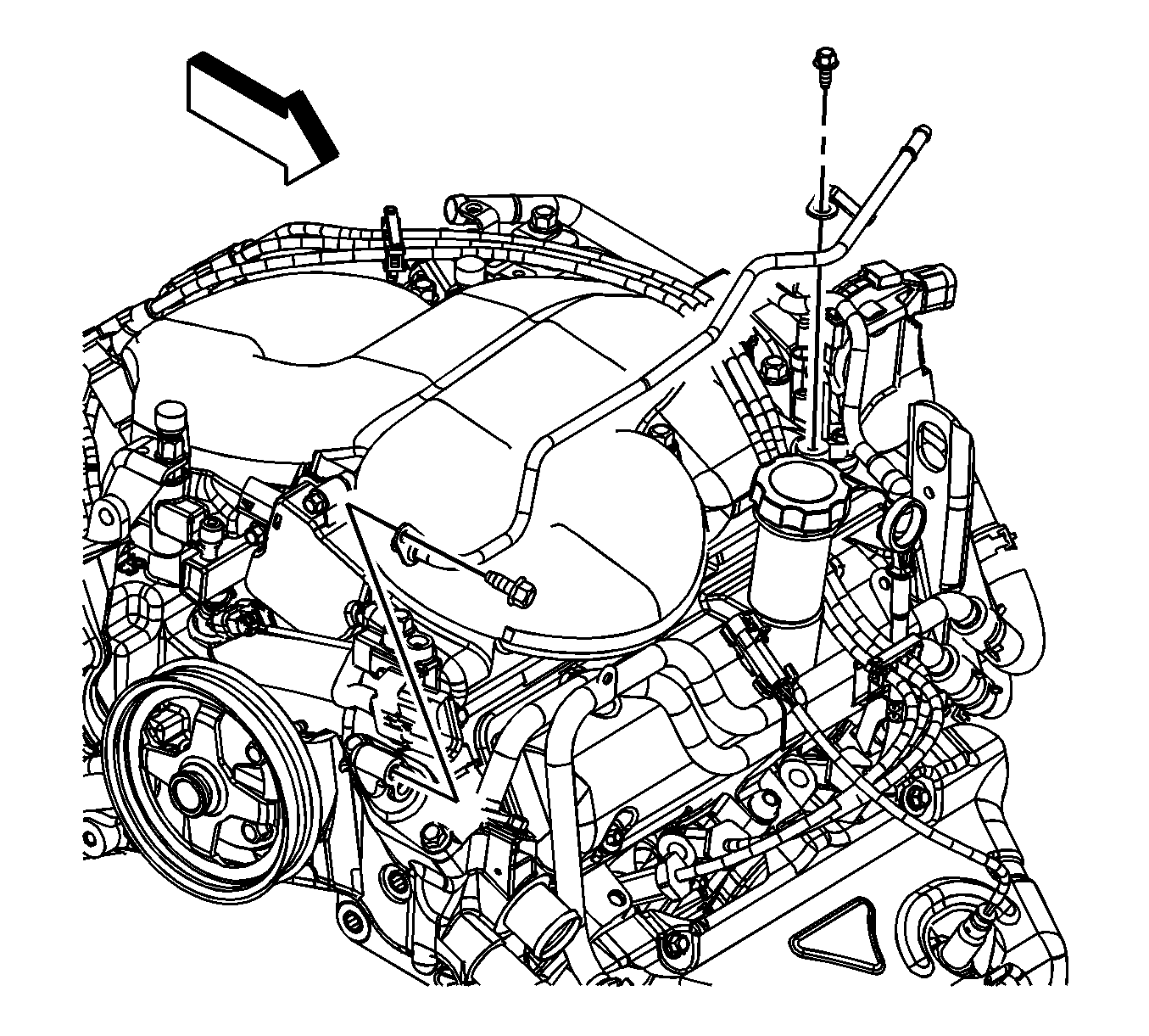
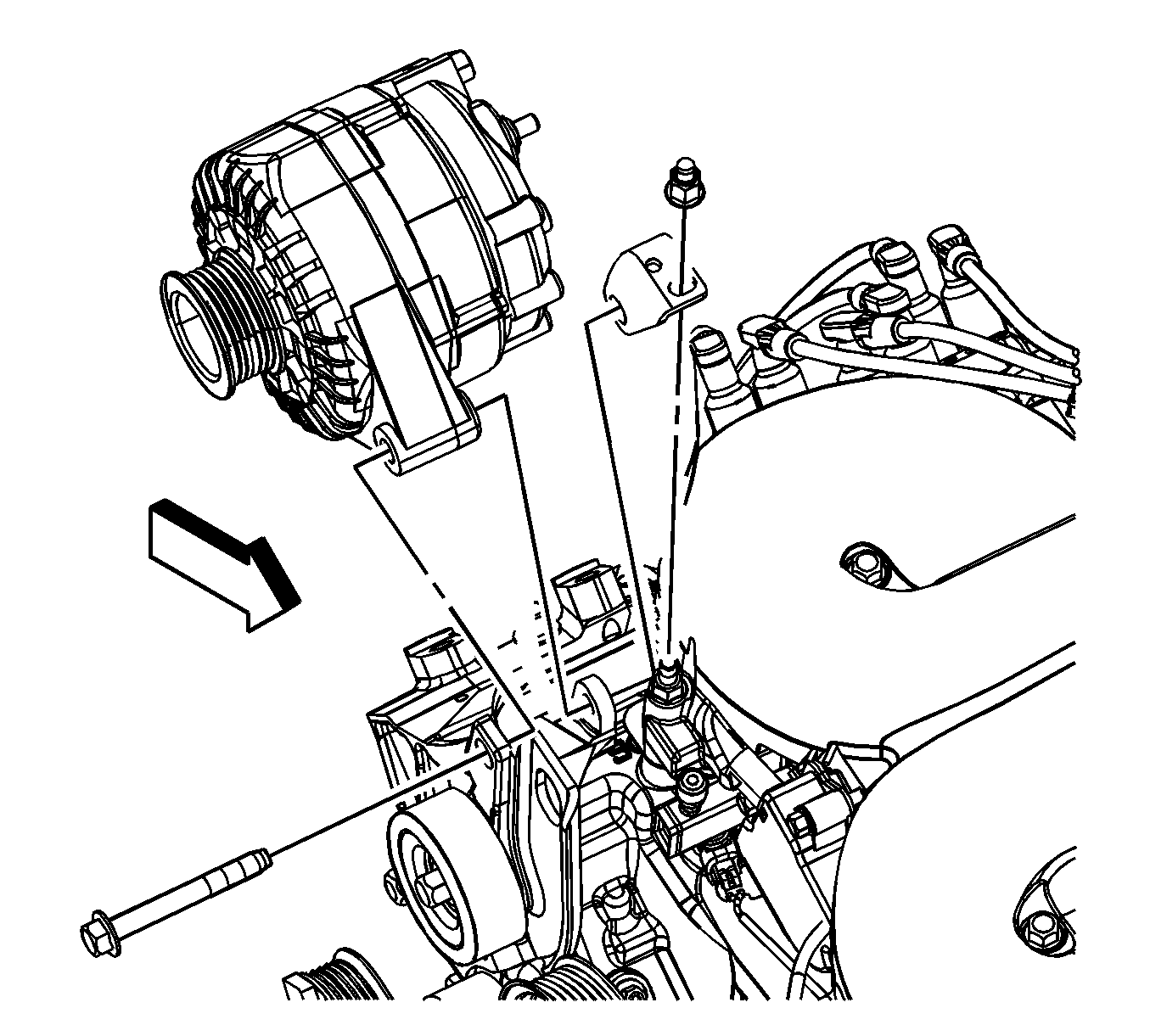
- Remove the generator upper bolt.
- Remove the generator ball stud.
- Remove the generator rear brace.
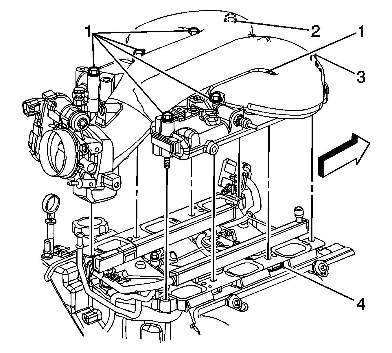
- Remove the upper intake manifold bolts (1, 2) and stud (3).
- Separate and remove the upper intake manifold from the lower intake manifold.
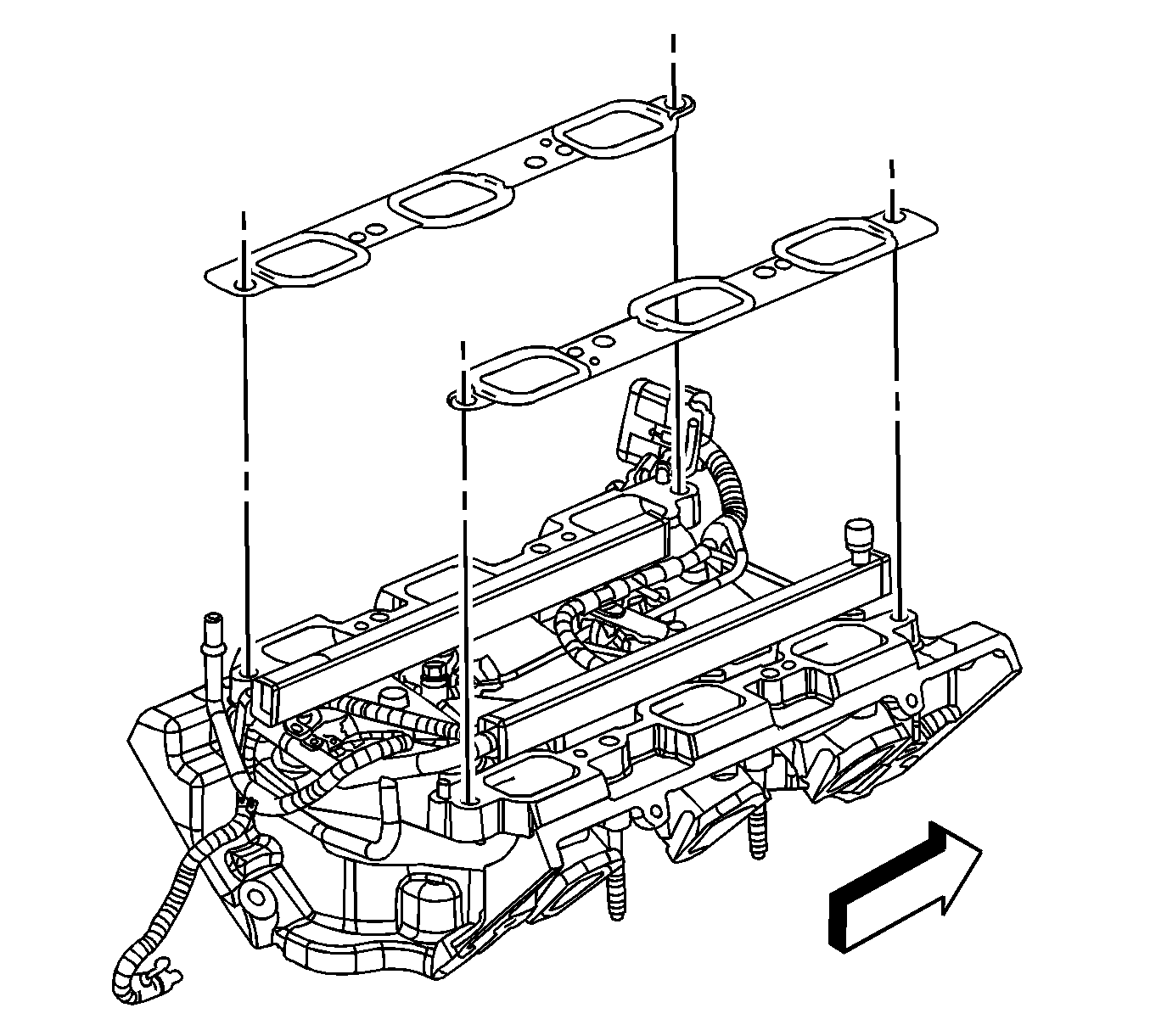
- Remove the upper to lower intake manifold gaskets.
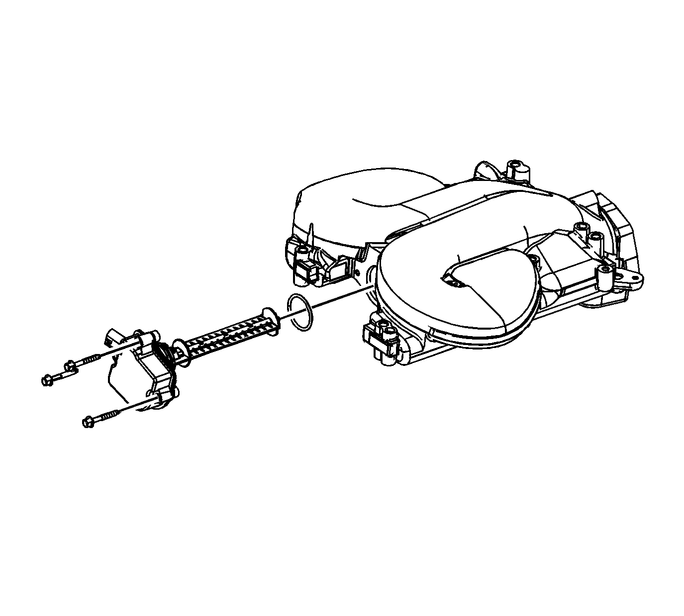
- Remove the inlet manifold tuning valve bolts and valve.
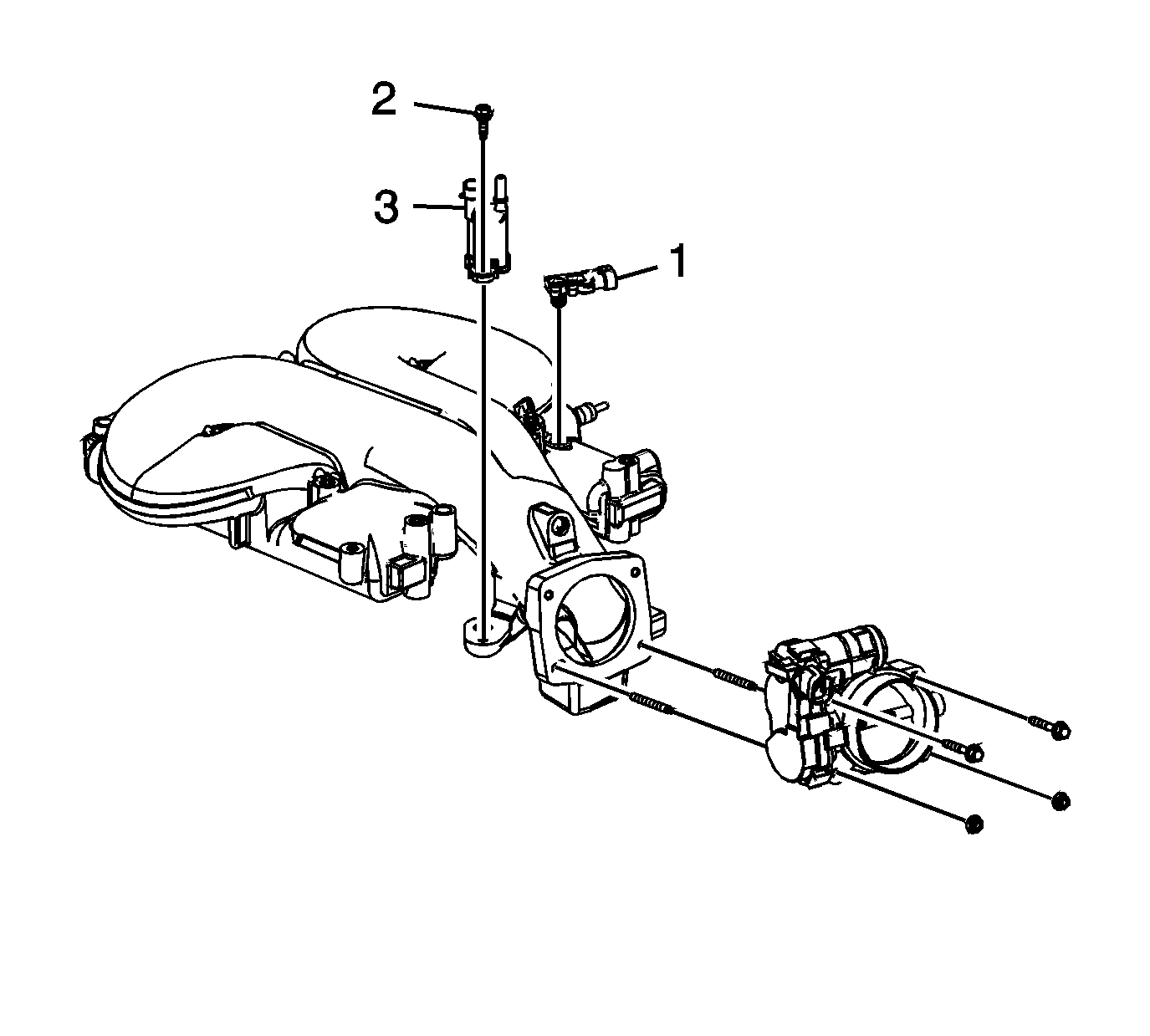
- Remove the throttle body bolts/studs and throttle body.
- Remove the MAP sensor bracket and sensor (1).
- Remove the EVAP canister purge solenoid valve bolt (2) and valve (3).
- Clean the upper intake to lower intake gasket mating surfaces.
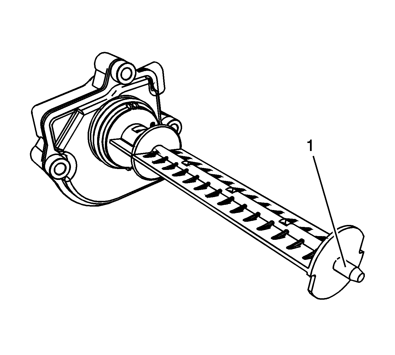
- Inspect the intake manifold tuning valve seal for damage. The tuning valve blade attachment to the motor should be tight, with no looseness or slack present, Replace as necessary.
- Apply lubricant to the nose of the valve blade (1). Refer to Adhesives, Fluids, Lubricants, and Sealers for the correct part number.
Installation Procedure
- Inspect the EVAP canister purge solenoid valve seal for damage, replace as necessary.
- Install the EVAP canister purge solenoid valve (3) and bolt (2).
- Inspect the MAP sensor seal for damage, replace as necessary.
- Install the MAP sensor and bracket.
- Inspect the throttle body seal for damage, replace as necessary.
- Apply threadlock to the throttle body bolts/studs threads. Refer to Adhesives, Fluids, Lubricants, and Sealers for the correct part number.
- Install the throttle body and bolts/studs.
- Install the inlet manifold tuning valve, and bolts.
- Install the NEW upper to lower intake manifold gaskets.
- Set the upper intake manifold onto the lower intake manifold.
- Apply threadlock to the upper intake manifold bolts/stud threads. Refer to Adhesives, Fluids, Lubricants, and Sealers for the correct part number.
- Install the upper intake manifold bolts (1, 2) and stud (3).
- Install the generator rear brace.
- Install the generator ball stud.
- Install the generator upper bolt.
- Install the 2 ignition coil bolts (1).
- Install the inlet and outlet pipe (2, 3) to the studs.
- Install the heater inlet and outlet pipe nuts (1) to the throttle body studs.
- Install the left side spark plug wires.
- Connect the left side spark plug wires to the spark plugs.
- Connect the left side spark plug wires to the ignition coil.
- Engage the spark plug wire retainer clips to the intake manifold bracket and the heater inlet/outlet pipe.
- Install the air cleaner outlet duct. Refer to Air Cleaner Outlet Duct Replacement .
- Connect the inlet manifold valve electrical connector (1).
- Connect the EVAP canister purge solenoid electrical connector (1).
- Connect the ETC electrical connector (2).
- Connect the MAP sensor electrical connector (1).
- Install the radiator surge tank inlet pipe.
- Install the radiator surge tank inlet pipe bolts.
- Install the radiator surge tank inlet hose to the inlet pipe.
- Position the radiator surge tank inlet hose clamp.
- Install the brake booster vacuum hose (1) to the intake manifold.
- Position the vacuum hose clamp at the intake manifold.
- Install the PCV foul air tube. Refer to Plastic Collar Quick Connect Fitting Service .
- Install the PCV fresh air tube. Refer to Plastic Collar Quick Connect Fitting Service .
- Install the fuel and EVAP pipes to the retainer clip (2) and close the clip.
- Connect the fuel feed pipe (3) quick connect fitting to the fuel rail. Refer to Metal Collar Quick Connect Fitting Service .
- Connect the EVAP emission pipe (1) to the purge solenoid. Refer to Plastic Collar Quick Connect Fitting Service .
- Fill the cooling system. Refer to Cooling System Draining and Filling .
- Install the intake manifold cover. Refer to Intake Manifold Cover Replacement .
- Connect the negative battery cable. Refer to Battery Negative Cable Disconnection and Connection .
Notice: Refer to Fastener Notice in the Preface section.

Tighten
Tighten the bolt to 16 N·m (12 lb ft).
Tighten
Tighten the bolts/studs to 10 N·m (89 lb in).

Tighten
Tighten the bolts to 10 N·m (89 lb in).


Tighten
Tighten the bolts and stud to 25 N·m (18 lb ft).

Tighten
Tighten the bolt to 20 N·m (15 lb ft).
Tighten
Tighten the bolt to 50 N·m (37 lb ft).

Tighten
Tighten the bolts to 25 N·m (18 lb ft).

Tighten
Tighten the nuts to 10 N·m (89 lb in).


Tighten
Tighten the bolts to 10 N·m (89 lb in).


