| Table 1: | Ambient Air Temperature Sensor |
| Table 2: | Driver Information Center (DIC) |
| Table 3: | Electronic Compass Module |
| Table 4: | Engine Oil Level Switch (L26/L32) |
| Table 5: | Engine Oil Level Switch (LS4) |
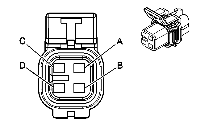
| Table 6: | Engine Oil Pressure (EOP) Switch (L26/L32) |
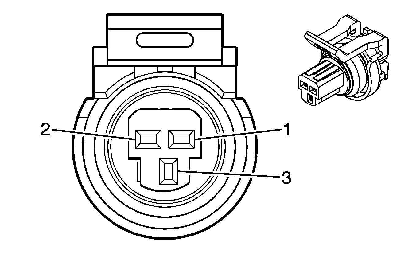
| Table 7: | Engine Oil Pressure (EOP) Sensor (LS4) |
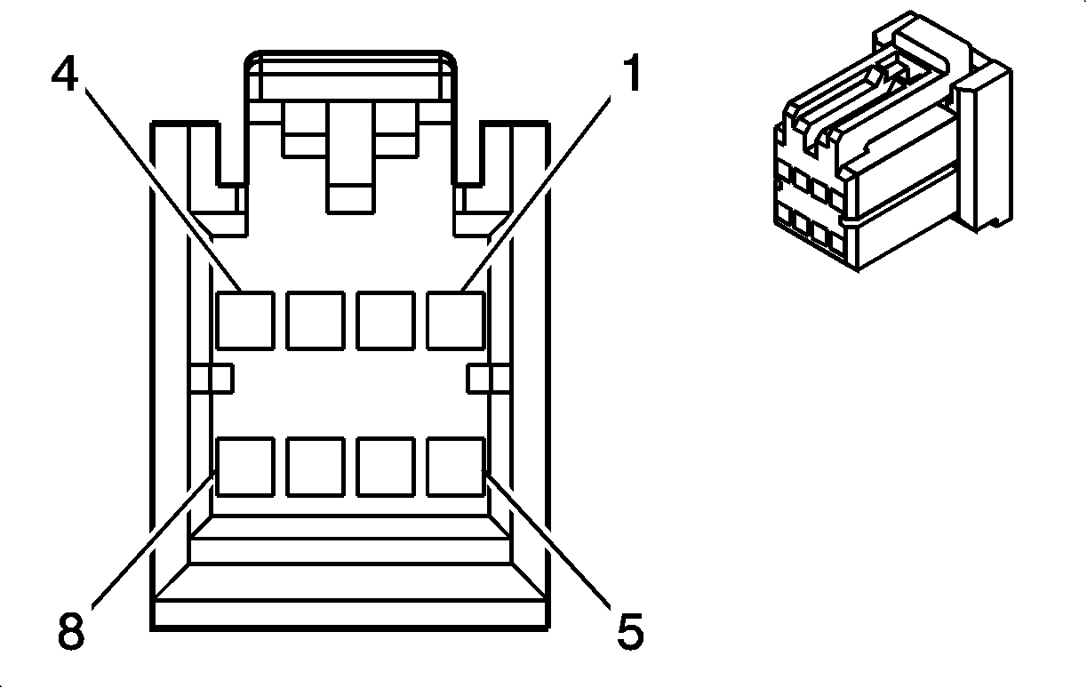
| Table 8: | Fuel Pump and Sender Assembly |
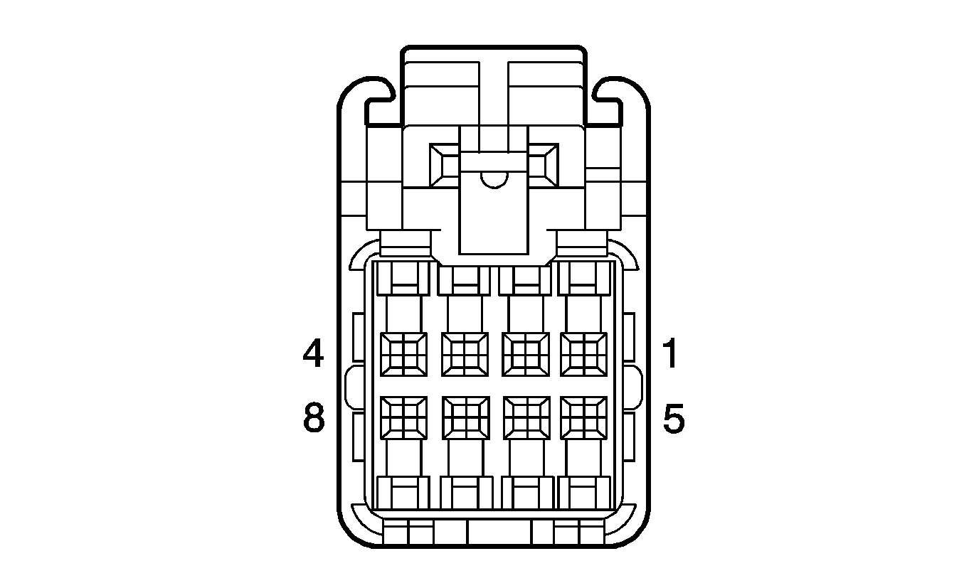
| Table 9: | Head Up Display (HUD) (UV6) |
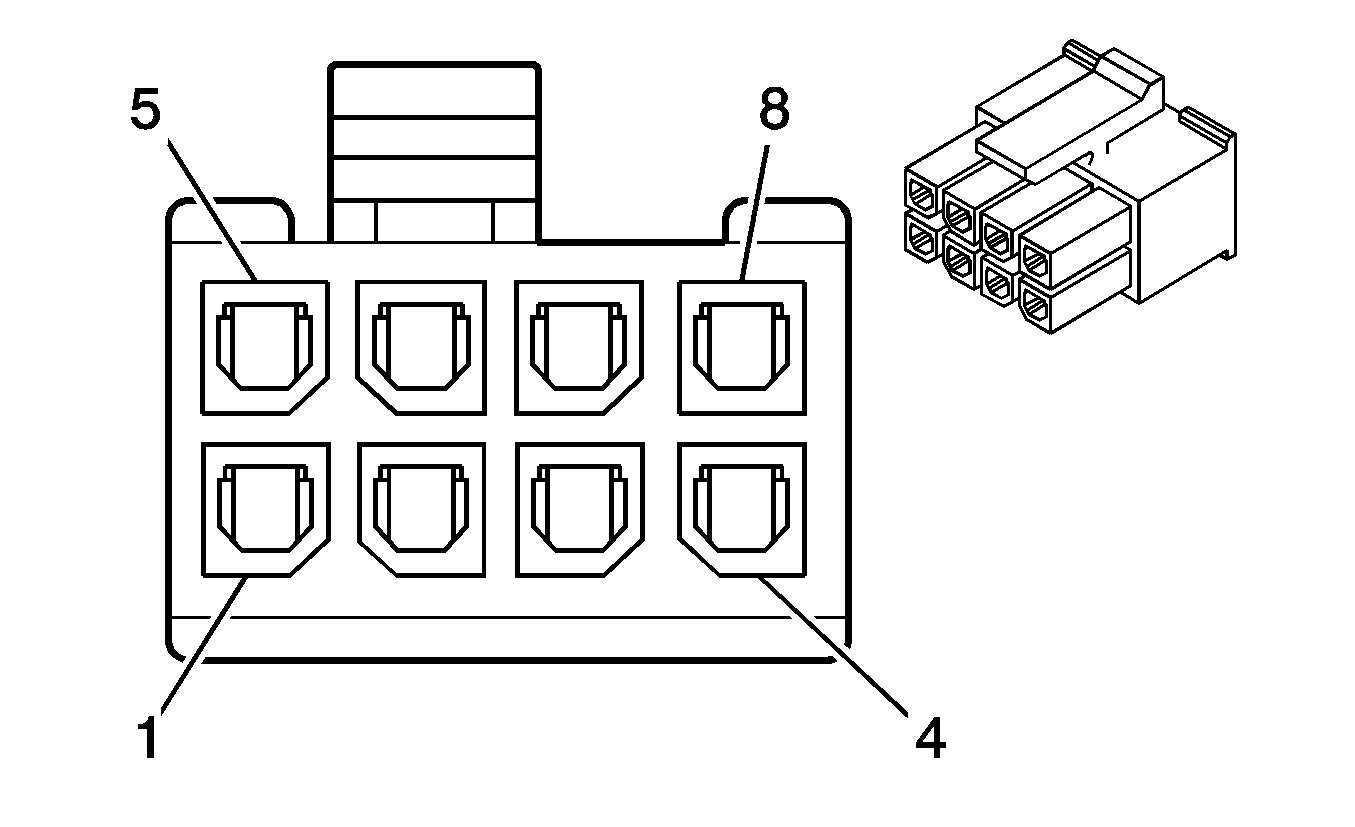
| Table 10: | Head Up Display (HUD) Switch (UV6) |
| Table 11: | Instrument Panel Cluster (IPC) |
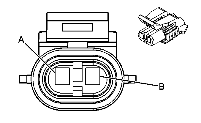
| |||||||
|---|---|---|---|---|---|---|---|
Connector Part Information |
| ||||||
Pin | Wire Color | Circuit No. | Function | ||||
A | L-GN/BK | 735 | Ambient Air Temperature Sensor Signal | ||||
B | YE | 61 | Low Reference | ||||
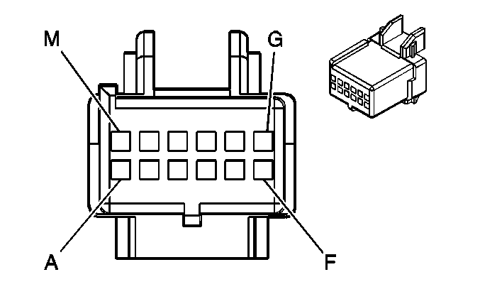
| |||||||
|---|---|---|---|---|---|---|---|
Connector Part Information |
| ||||||
Pin | Wire Color | Circuit No. | Function | ||||
A | L-GN/BK | 735 | Ambient Air Temperature Sensor Signal | ||||
B | BN | 1779 | Compass Data Signal | ||||
C | D-BU | 1778 | Compass Clock Signal | ||||
D-E | -- | -- | Not Used | ||||
F | BK/WH | 1551 | Ground | ||||
G | YE | 61 | Low Reference | ||||
H-K | -- | -- | Not Used | ||||
L | OG | 5240 | Battery Positive Voltage | ||||
M | YE | 1127 | Trip Computer Class 2 Serial Data | ||||
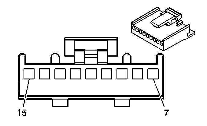
| |||||||
|---|---|---|---|---|---|---|---|
Connector Part Information |
| ||||||
Pin | Wire Color | Circuit No. | Function | ||||
7-8 | -- | -- | Not Used | ||||
9 | WH | 193 | Rear Defog On Signal | ||||
10 | -- | -- | Not Used | ||||
11 | BN | 1779 | Compass Data Signal | ||||
12 | D-BU | 1778 | Compass Clock Signal | ||||
13 | PK | 739 | Ignition 1 Voltage | ||||
14 | BK | 550 | Ground | ||||
15 | -- | -- | Not Used | ||||
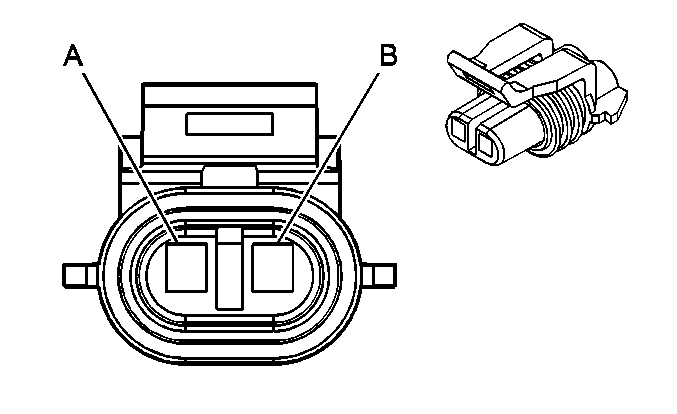
| |||||||
|---|---|---|---|---|---|---|---|
Connector Part Information |
| ||||||
Pin | Wire Color | Circuit No. | Function | ||||
A | BN | 1174 | Oil Level Switch Signal | ||||
B | BK/WH | 451 | Ground | ||||
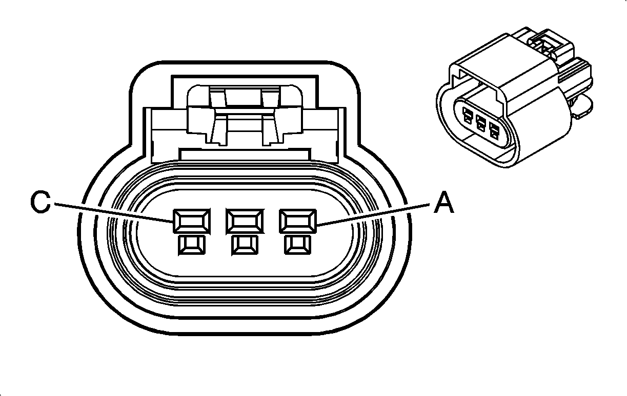
| |||||||
|---|---|---|---|---|---|---|---|
Connector Part Information |
| ||||||
Pin | Wire Color | Circuit No. | Function | ||||
A | BN | 1174 | Oil Level Switch Signal | ||||
B | -- | -- | Not Used | ||||
C | BK/WH | 451 | Ground | ||||
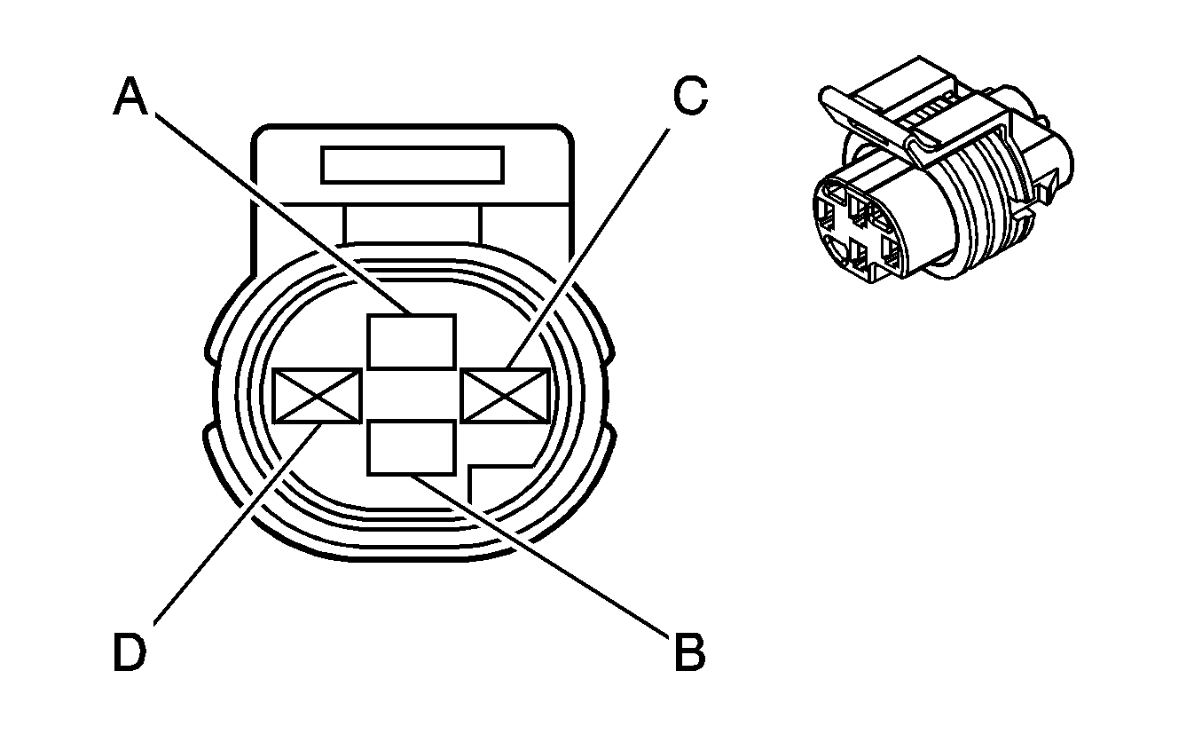
| |||||||
|---|---|---|---|---|---|---|---|
Connector Part Information |
| ||||||
Pin | Wire Color | Circuit No. | Function | ||||
A | TN/BK | 231 | Oil Pressure Switch Signal | ||||
B | BK/WH | 451 | Ground | ||||
C-D | -- | -- | Not Used | ||||
| |||||||
|---|---|---|---|---|---|---|---|
Connector Part Information |
| ||||||
Pin | Wire Color | Circuit No. | Function | ||||
1 | BK | 2755 | Low Reference | ||||
2 | GY | 2705 | 5-Volt Reference A | ||||
3 | TN/WH | 331 | Oil Pressure Sensor Signal | ||||
| |||||||
|---|---|---|---|---|---|---|---|
Connector Part Information |
| ||||||
Pin | Wire Color | Circuit No. | Function | ||||
A | PU | 30 | Fuel Level Sensor Signal | ||||
B | GY | 120 | Fuel Pump Supply Voltage | ||||
C | BK | 150 | Ground | ||||
D | BK/WH | 651 | Low Reference | ||||
| |||||||
|---|---|---|---|---|---|---|---|
Connector Part Information |
| ||||||
Pin | Wire Color | Circuit No. | Function | ||||
1 | BN/WH | 1048 | HUD Class 2 Serial Data | ||||
2 | YE | 621 | HUD Image Up Control | ||||
3 | BN | 620 | HUD Image Down Control | ||||
4 | BK/WH | 1551 | Ground | ||||
5 | WH | 717 | Illuminated Display Signal | ||||
6 | OG | 5240 | Battery Positive Voltage | ||||
7 | BN | 622 | HUD Switch Signal | ||||
8 | WH | 1104 | Low Reference | ||||
| |||||||
|---|---|---|---|---|---|---|---|
Connector Part Information |
| ||||||
Pin | Wire Color | Circuit No. | Function | ||||
1 | GY | 8 | Instrument Panel Lamp Supply Voltage | ||||
2 | BK | 150 | Ground | ||||
3 | WH | 1104 | Low Reference | ||||
4 | BN | 620 | HUD Image Down Control | ||||
5 | BN | 622 | HUD Switch Signal | ||||
6 | WH | 717 | Illuminated Display Signal | ||||
7 | YE | 621 | HUD Image Up Control | ||||
8 | -- | -- | Not Used | ||||
| |||||||
|---|---|---|---|---|---|---|---|
Connector Part Information |
| ||||||
Pin | Wire Color | Circuit No. | Function | ||||
1 | BK/WH | 1551 | Ground | ||||
2 | TN/WH | 33 | Brake Warning Indicator Control | ||||
3 | GY | 1036 | IPC Class 2 Serial Data | ||||
4-6 | -- | -- | Not Used | ||||
7 | BN/WH | 419 | MIL Control | ||||
8 | OG | 5240 | Battery Positive Voltage | ||||
