For 1990-2009 cars only
Tools Required
J 21177-A Drum to Brake Shoe Clearance Gauge
Park Brake Shoe Adjustment
Caution: Refer to Brake Dust Caution in the Preface section.
- Apply and fully release the park brake lever.
- Verify that the park brake lever releases completely.
- Turn ON the ignition. Verify that the red BRAKE warning indicator lamp is off.
- Turn OFF the ignition.
- Raise and support the vehicle. Refer to Lifting and Jacking the Vehicle.
- Remove the rear tire and wheel assemblies. Refer to Tire and Wheel Removal and Installation.
- Remove the rear disc brake rotors. Refer to Rear Brake Rotor Replacement.
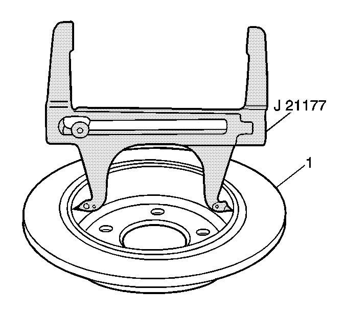
- Place the inside measurement contacts of the J 21177-A at the widest point of the drum portion of the brake rotor (1).
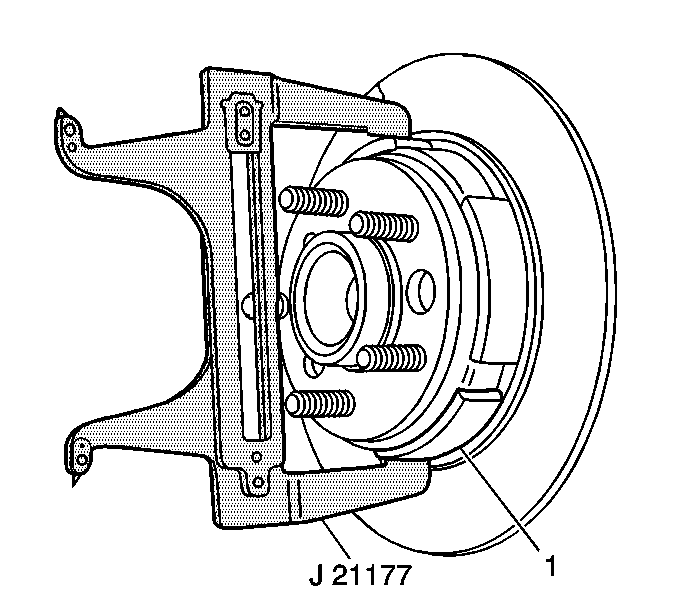
- Tighten the set screw on the tool in order to ensure the proper measurement when removing the tool from the drum.
- Position the outside measurement contacts of the J 21177-A over the park brake shoe (1) at the widest point.
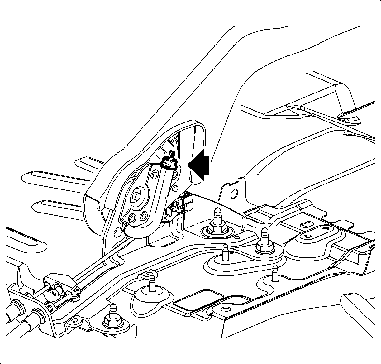
- Adjust the park brake shoe-to-drum clearance by rotating the adjustment nut on the park brake actuator.
- Install the rear brake rotors. Refer to Rear Brake Rotor Replacement.
- Install the rear tire and wheel assemblies. Refer to Tire and Wheel Removal and Installation.
- Apply the park brake lever. Inspect the rotation of the rear wheels:
- If the rear tire and wheel assemblies rotate forward or do not exhibit drag rearward, proceed to the park brake cable adjustment.
- Release the park brake lever. Verify that the wheels rotate freely.
Important: Do not operate the park brake lever with the rear disc brake rotors removed.


Important: If the gap between the adjuster nut and the adjuster screw exceeds 5 mm (0.25 in) during the adjustment procedure, the park brake shoe must be replaced.
Specification
0.38 mm (0.015 in)
| • | The wheels should not rotate forward. |
| • | The wheels should drag or not rotate rearward. |
Park Brake Cable Adjustment
- Remove the front floor console. Refer to Console Replacement.
- With the park brake lever in the fully released position, using ONLY hand tools, loosen the adjusting nut completely to the end of the front cable threaded rod.
- Raise the park brake lever 1 detent position.
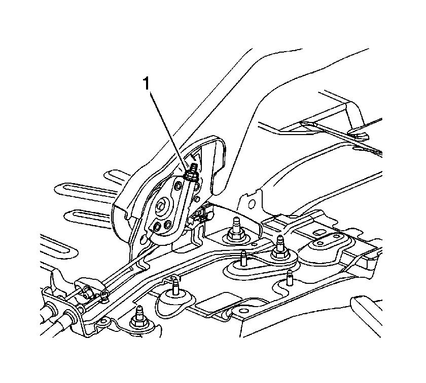
- Using ONLY hand tools, tighten the park brake cable adjusting nut (1) until light to moderate drag is exhibited while rotating the rear wheels.
- Attempt to rotate the rear wheels. There should be no rotation forward or rearward.
- Fully release the park brake lever.
- Verify the park brake is released by rotating the rear wheels. The wheels should rotate freely and exhibit no park brake shoe drag.
- If the wheels do not rotate freely, repeat the park brake cable adjustment procedure.
- Raise the park brake lever 3 detent positions and attempt to rotate the rear wheels:
- Install the front floor console. Refer to Console Replacement.
- Release the park brake lever.

Notice: Refer to Fastener Notice in the Preface section.

| - | One of the wheels should not rotate forward or rearward. |
| - | The other wheel should not rotate forward or rearward, or should require substantial effort to rotate. |
