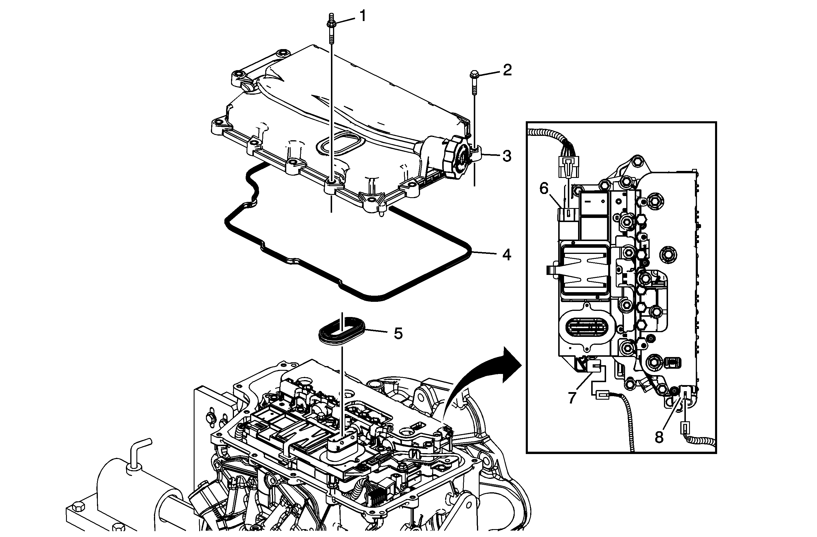
| Table 1: | Control Valve Body Cover Removal |
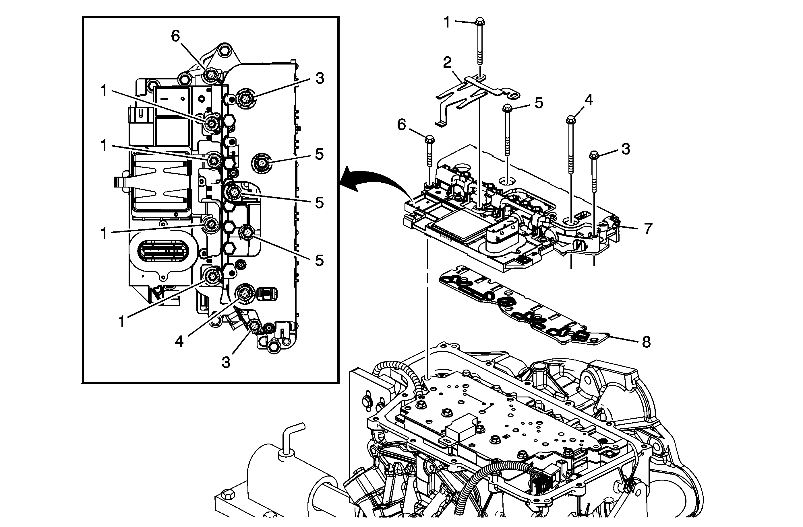
| Table 2: | Control Solenoid (w/Body and TCM) Valve Assembly Removal |
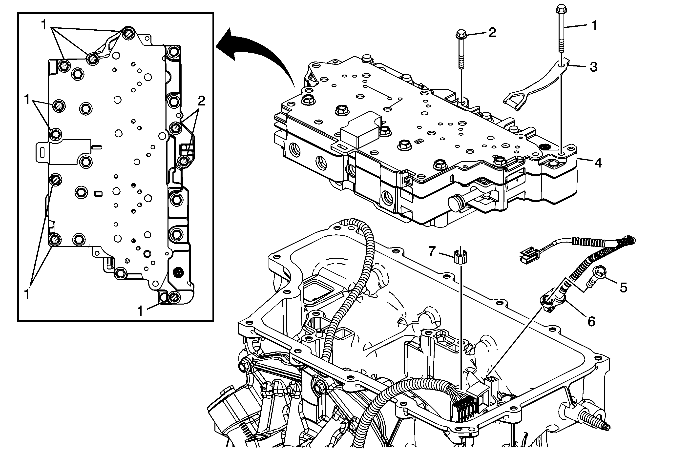
| Table 3: | Control Valve Body Assembly and Output Speed Sensor Removal |
Control Valve Body Cover Removal

Callout | Component Name |
|---|---|
1 | Control Valve Body Cover Stud M6 x 30 (Qty: 2) |
2 | Control Valve Body Cover Bolt M6 x 30 (Qty: 12) |
3 | Control Valve Body Cover |
4 | Control Valve Body Cover Gasket Tip |
5 | Control Valve Body Cover Wiring Connector Hole Seal Notice: Support the control solenoid valve assembly around the connector when removing the seal. Excessive pulling force can damage the internal electrical connections. |
6 | Shift Position Switch Connector |
7 | Output Speed Sensor Connector |
8 | Input Speed Sensor Connector |
Control Solenoid (w/Body and TCM) Valve Assembly Removal

Callout | Component Name | ||||
|---|---|---|---|---|---|
1 | Control Valve Body Bolt M6 x 80 (Qty: 4) | ||||
2 | Control Solenoid Valve Spring | ||||
3 | Control Valve Body Bolt M6 x 65 (Qty: 2) | ||||
4 | Control Valve Body Bolt M6 x 42 (Qty: 1) | ||||
5 | Control Valve Body Bolt M6 x 95 (Qty: 3) | ||||
6 | Control Valve Body Bolt M6 x 55 (Qty: 1) | ||||
7 | Control Solenoid (w/Body and TCM) Valve Assembly | ||||
8 | Control Solenoid Valve Assembly Filter Plate Notice: Use care when removing or installing the filter plate assembly. A broken or missing retaining tab may not adequately secure the filter plate to the control solenoid valve assembly, resulting in possible damage or contamination. Tip
|
Control Valve Body Assembly and Output Speed Sensor Removal

Callout | Component Name |
|---|---|
1 | Control Valve Body Bolt M6 x 65 (Qty: 8) |
2 | Control Valve Body Bolt M6 x 55 (Qty: 2) |
3 | Manual Shaft Detent Assembly |
4 | Control Valve Body Assembly |
5 | A/Trans Output Speed Sensor Bolt M6 x 25 |
6 | A/Trans Output Speed Sensor |
7 | 1-2-3-4 Clutch Fluid Passage Seal Tip |
