| ||||||
|---|---|---|---|---|---|---|
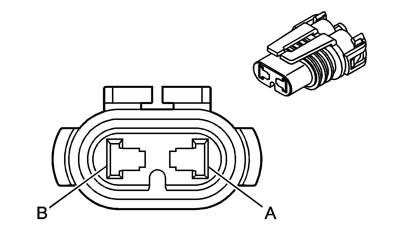
Connector Part Information |
| |||||
Pin | Wire Color | Function | ||||
A | BLK/RED | Supply Voltage | ||||
B | WHT/BLK | Ground | ||||
| ||||||
|---|---|---|---|---|---|---|
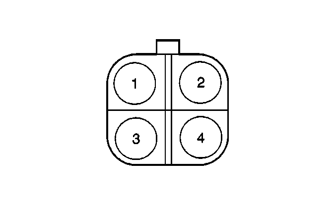
Connector Part Information |
| |||||
Pin | Wire Color | Function | ||||
1 | BLK/ORN | Air Pump Relay Control | ||||
2 | BLK | Air Pump Relay Supply Voltage | ||||
3 | BLK/RED | Air Pump Motor Supply Voltage | ||||
4 | BLK | Air Pump Relay Supply Voltage | ||||
| ||||||
|---|---|---|---|---|---|---|
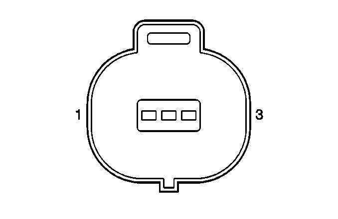
Connector Part Information |
| |||||
Pin | Wire Color | Function | ||||
1 | BRN | Ground | ||||
2 | LT GRN | Powertrain Control Module Signal | ||||
3 | YEL | 5 Volt Reference | ||||
| ||||||
|---|---|---|---|---|---|---|
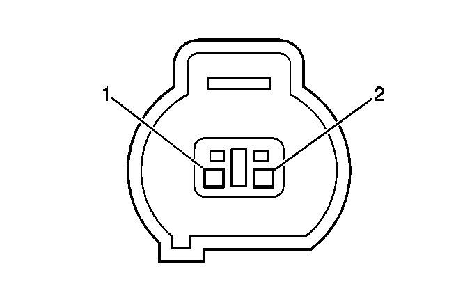
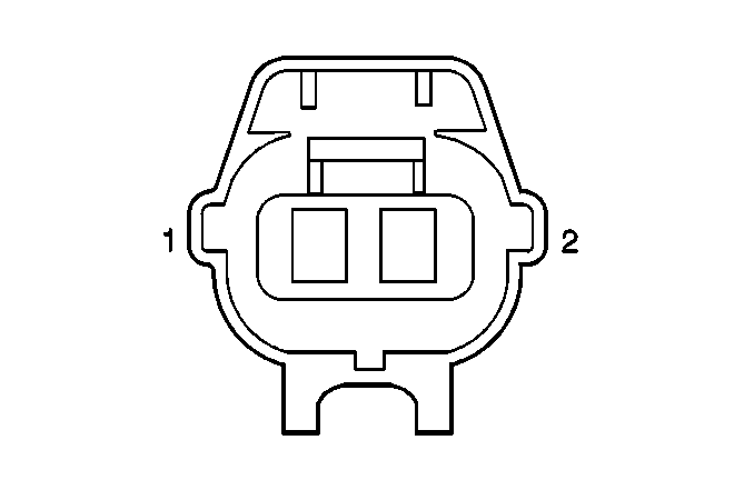
Connector Part Information |
| |||||
Pin | Wire Color | Function | ||||
1 | BLK | Supply Voltage | ||||
2 | BLK/BLU | Powertrain Control Module Signal | ||||
| ||||||
|---|---|---|---|---|---|---|
Connector Part Information |
| |||||
Pin | Wire Color | Function | ||||
1 | BLK | Ambient Air Temperature Sensor Input | ||||
2 | BLK/BLU | Ground | ||||

| ||||||
|---|---|---|---|---|---|---|
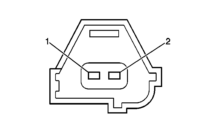
Connector Part Information |
| |||||
Pin | Wire Color | Function | ||||
1 | RED/BLK | Back Up Lamp Switch Signal Circuit | ||||
2 | RED/WHT | Back Up Lamp Switch Feed Circuit | ||||
| ||||||
|---|---|---|---|---|---|---|
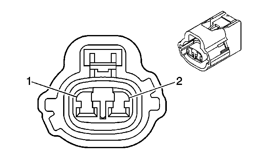
Connector Part Information |
| |||||
Pin | Wire Color | Function | ||||
1 | BLK | Camshaft Position Input | ||||
2 | WHT | Sensor Ground | ||||
| ||||||
|---|---|---|---|---|---|---|
Connector Part Information |
| |||||
Pin | Wire Color | Function | ||||
1 | YEL | CMP Actuator High Control | ||||
2 | BLK/YEL | CMP Actuator Low Control | ||||
| ||
|---|---|---|
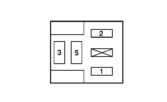
Connector Part Information | -- | |
Pin | Wire Color | Function |
1 | BLK | Relay Coil Feed Circuit |
2 | GRN/RED | Relay Coil Ground Circuit |
3 | BLK/RED | Relay Switch Ground Circuit |
5 | WHT/BLK | Relay Switch Feed Circuit |

| ||||||
|---|---|---|---|---|---|---|
Connector Part Information |
| |||||
Pin | Wire Color | Function | ||||
1 | RED | CPP Feed Circuit | ||||
2 | BLK | CPP Signal Circuit | ||||

| ||||||
|---|---|---|---|---|---|---|
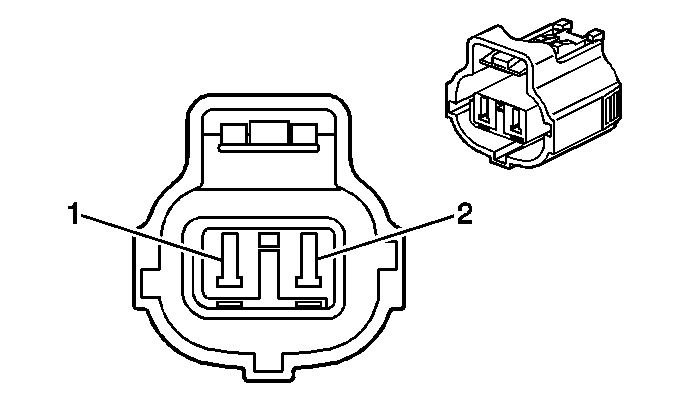
Connector Part Information |
| |||||
Pin | Wire Color | Function | ||||
1 | BLK | Crankshaft Position Input | ||||
2 | WHT | Sensor Ground | ||||
| ||||||
|---|---|---|---|---|---|---|
Connector Part Information |
| |||||
Pin | Wire Color | Function | ||||
1 | BRN | Sensor Ground | ||||
2 | WHT | ECT Input | ||||

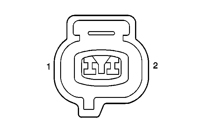
| ||
|---|---|---|
Connector Part Information | -- | |
Pin | Wire Color | Function |
1 | BLK/WHT | Relay Coil Feed Circuit |
2 | WHT/BLK | Relay Coil Ground Circuit |
3 | BLK | Relay Switch Ground Circuit |
5 | RED/WHT | Relay Switch Feed Circuit |
| ||||||
|---|---|---|---|---|---|---|
Connector Part Information |
| |||||
Pin | Wire Color | Function | ||||
1 | RED | EVAP Control | ||||
2 | BLK | EVAP Feed Circuit | ||||

| ||||||
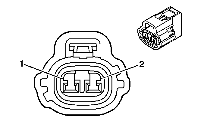
|---|---|---|---|---|---|---|
Connector Part Information |
| |||||
Pin | Wire Color | Function | ||||
1 | BLU/BLK | EVAP Control Circuit | ||||
2 | BLK | EVAP Feed Circuit | ||||
| ||||||
|---|---|---|---|---|---|---|
Connector Part Information |
| |||||
Pin | Wire Color | Function | ||||
1 | BLU | EVAP Control Circuit | ||||
2 | BLK | EVAP Feed Circuit | ||||

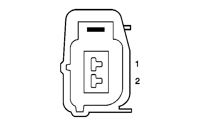
| ||||||
|---|---|---|---|---|---|---|
Connector Part Information |
| |||||
Pin | Wire Color | Function | ||||
1 | BLK | EVAP Feed Circuit | ||||
2 | BLU/WHT | EVAP Control Circuit | ||||
| ||||||
|---|---|---|---|---|---|---|
Connector Part Information |
| |||||
Pin | Wire Color | Function | ||||
1 | BLK/WHT | Fuel Injector #1 Feed Circuit | ||||
2 | YEL | Fuel Injector #1 Control Circuit | ||||

| ||||||
|---|---|---|---|---|---|---|
Connector Part Information |
| |||||
Pin | Wire Color | Function | ||||
1 | BLK/WHT | Fuel Injector #2 Feed Circuit | ||||
2 | BLK | Fuel Injector #2 Control Circuit | ||||

| ||||||
|---|---|---|---|---|---|---|
Connector Part Information |
| |||||
Pin | Wire Color | Function | ||||
1 | BLK/WHT | Fuel Injector #3 Feed Circuit | ||||
2 | WHT | Fuel Injector #3 Control Circuit | ||||

| ||||||
|---|---|---|---|---|---|---|
Connector Part Information |
| |||||
Pin | Wire Color | Function | ||||
1 | BLK/WHT | Fuel Injector #4 Control Circuit | ||||
2 | BLU | Fuel Injector #4 Feed Circuit | ||||
| ||||||
|---|---|---|---|---|---|---|
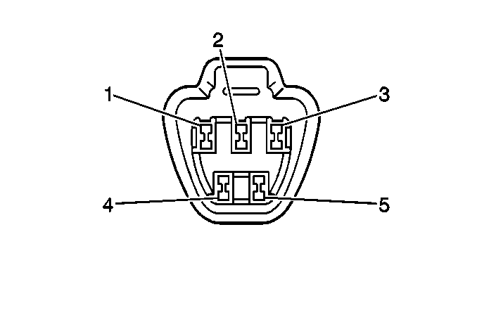
Connector Part Information |
| |||||
Pin | Wire Color | Function | ||||
1 | -- | Not Used | ||||
2 | YEL | Fuel Gage | ||||
3 | BRN | Low Fuel Indicator | ||||
4 | BLK/RED | Fuel Pump Feed Circuit | ||||
5 | WHT/BLK | Ground | ||||
| ||||||
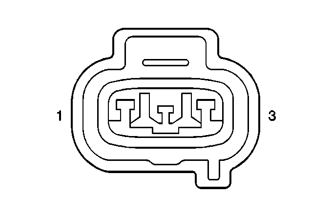
|---|---|---|---|---|---|---|
Connector Part Information |
| |||||
Pin | Wire Color | Function | ||||
1 | BRN | Sensor Ground | ||||
2 | BLU | Fuel Tank Pressure Input | ||||
3 | YEL | Reference Voltage | ||||
| ||||||
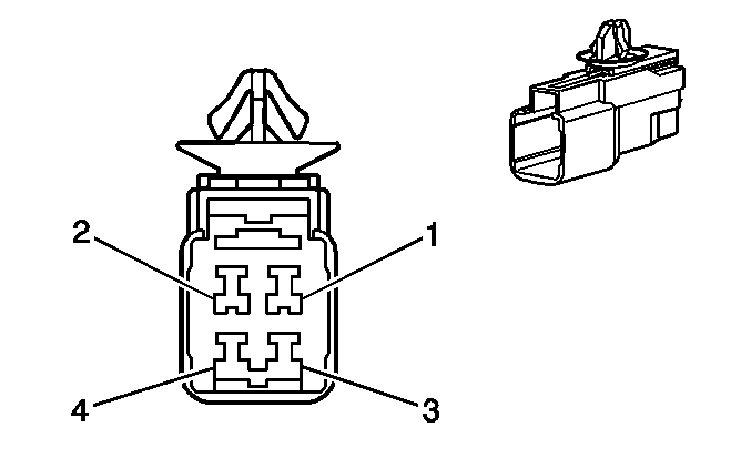
|---|---|---|---|---|---|---|
Connector Part Information |
| |||||
Pin | Wire Color | Function | ||||
1 | BLK | HO2S1 Heater Feed Circuit | ||||
2 | PNK | HO2S1 Heater Control Circuit | ||||
3 | BRN | Ground | ||||
4 | RED | HO2S1 Input | ||||
| ||||||
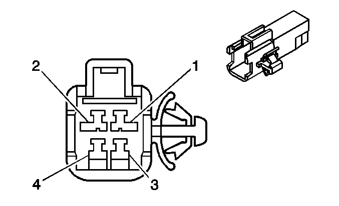
|---|---|---|---|---|---|---|
Connector Part Information |
| |||||
Pin | Wire Color | Function | ||||
1 | BLK | HO2S2 Heater Feed Circuit | ||||
2 | PNK/BLK | HO2S2 Heater Control Circuit | ||||
3 | BRN | Ground | ||||
4 | WHT | HO2S2 Input Circuit | ||||
| ||||||
|---|---|---|---|---|---|---|
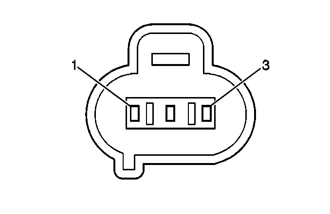
Connector Part Information |
| |||||
Pin | Wire Color | Function | ||||
1 | BLK/BLU | IAC Valve Open Control | ||||
2 | BLK | IAC Feed Circuit | ||||
3 | WHT/BLK | Ground | ||||
| ||||||
|---|---|---|---|---|---|---|
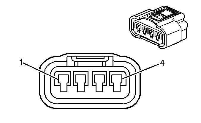
Connector Part Information |
| |||||
Pin | Wire Color | Function | ||||
1 | BLK/WHT | Ignition Coil Feed Circuit | ||||
2 | BLU/YEL | Ignition Fail Safe Input | ||||
3 | RED/BLU | Ignition Trigger Circuit | ||||
4 | WHT/BLK | Ground | ||||

| ||||||
|---|---|---|---|---|---|---|
Connector Part Information |
| |||||
Pin | Wire Color | Function | ||||
1 | BLK/WHT | Ignition Coil Feed Circuit | ||||
2 | BLU/YEL | Ignition Fail Safe Input | ||||
3 | YEL/GRN | Ignition Trigger Circuit | ||||
4 | WHT/BLK | Ground | ||||

| ||||||
|---|---|---|---|---|---|---|
Connector Part Information |
| |||||
Pin | Wire Color | Function | ||||
1 | BLK/WHT | Ignition Coil Feed Circuit | ||||
2 | BLU/YEL | Ignition Fail Safe Input | ||||
3 | GRY | Ignition Trigger Circuit | ||||
4 | WHT/BLK | Ground | ||||

| ||||||
|---|---|---|---|---|---|---|
Connector Part Information |
| |||||
Pin | Wire Color | Function | ||||
1 | BLK/WHT | Ignition Coil Feed Circuit | ||||
2 | BLU/YEL | Ignition Fail Safe Input | ||||
3 | WHT | Ignition Trigger Circuit | ||||
4 | WHT/BLK | Ground | ||||

| ||||||
|---|---|---|---|---|---|---|
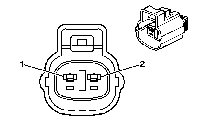
Connector Part Information |
| |||||
Pin | Wire Color | Function | ||||
1 | WHT | Knock Sensor Input Circuit | ||||
2 | BLK | Ground | ||||
| ||||||
|---|---|---|---|---|---|---|
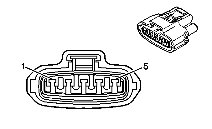
Connector Part Information |
| |||||
Pin | Wire Color | Function | ||||
1 | BLK | MAF Feed Circuit | ||||
2 | BLU/WHT | MAF Signal Low | ||||
3 | GRN | MAF Signal High | ||||
4 | YEL/BLK | IAT Sensor Input | ||||
5 | BRN | Sensor Ground | ||||
| ||||||
|---|---|---|---|---|---|---|
Connector Part Information |
| |||||
Pin | Wire Color | Function | ||||
1 | BLK/WHT | Noise Filter Feed Circuit | ||||
2 | -- | Not Used | ||||
| ||||||
|---|---|---|---|---|---|---|
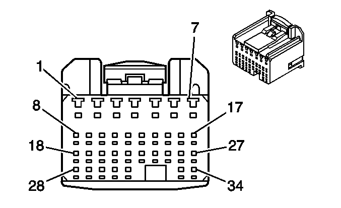
Connector Part Information |
| |||||
Pin | Wire Color | Function | ||||
1 | YEL | Fuel Injector 1 Control | ||||
2 | BLK | Fuel Injector 2 Control | ||||
3 | WHT | Fuel Injector 3 Control | ||||
4 | BLU | Fuel Injector 4 Control | ||||
5 | BLK/BLU | Idle Air Control (IAC) Valve Control | ||||
6 | WHT/BLK | Ground | ||||
7 | WHT/BLK | Ground | ||||
8 | RED/BLU | Ignition Trigger Signal Coil 1 | ||||
9 | YEL/GRN | Ignition Trigger Signal Coil 2 | ||||
10 | GRY | Ignition Trigger Signal Coil 3 | ||||
11 | WHT | Ignition Trigger Signal Coil 4 | ||||
12 | BLU/BLK | EVAP Canister Purge Solenoid Valve Control | ||||
13 | YEL | AC Pressure Switch | ||||
14 | BLK/YEL | Camshaft Position (CMP) Actuator Solenoid Valve High Control | ||||
15 | YEL | Camshaft Position (CMP) Actuator Solenoid Valve Control Low | ||||
16 | PNK | Line Pressure Control (PC) Solenoid Control Low* | ||||
17 | RED/WHT | Line Pressure Control (PC) Solenoid Control High* | ||||
18 | YEL | 5-Volt Reference Circuit | ||||
19 | WHT | Engine Coolant Temperature (ECT) Sensor Input | ||||
20 | YEL/BLK | Intake Air Temperature (IAT) Sensor Input | ||||
21 | LT GRN | Throttle Position (TP) Sensor Input | ||||
22 | -- | Not Used | ||||
23 | BLU/YEL | Ignition Fail Safe Input | ||||
24 | BLU/YEL | Rocker Arm Oil Control Solenoid Valve Control High | ||||
25 | BLK | Rocker Arm Oil Control Solenoid Valve Control Low | ||||
26 | BLK | Camshaft Position (CMP) Sensor Input | ||||
27 | BLK | Crankshaft Position (CKP) Sensor Input | ||||
28 | BRN | Sensor Ground | ||||
29 | -- | Not Used | ||||
30 | LT GRN | Secondary AIR Injection Pressure Sensor Input | ||||
31-32 | -- | Not Used | ||||
33 | BLK/BLU | Secondary AIR Injection Solenoid Valve Control | ||||
34 | WHT | CMP Sensor and CKP Sensor Ground | ||||
| ||||||
|---|---|---|---|---|---|---|
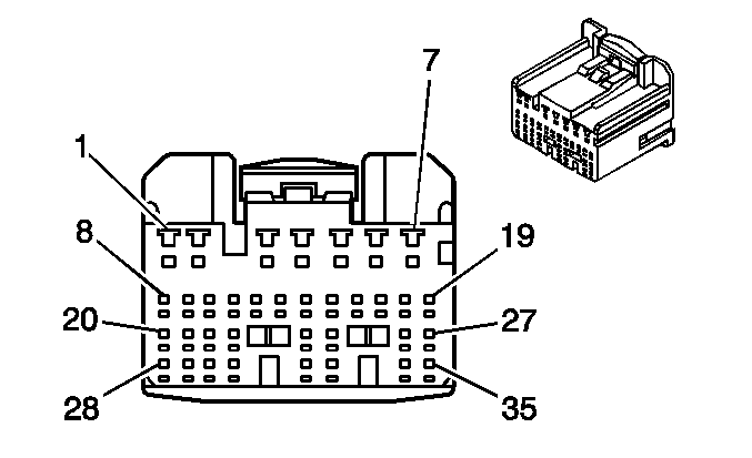
Connector Part Information |
| |||||
Pin | Wire Color | Function | ||||
1 | BLK | Knock Sensor (KS) Signal High | ||||
2 | WHT | Knock Sensor (KS) Signal Low | ||||
3 | BLK/ORN | Secondary AIR Injection Pump Relay Control | ||||
4 | PNK | Heated Oxygen Sensor (HO2S) 1 Heater Circuit Control | ||||
5 | WHT/BLK | Ground | ||||
6 | -- | Not Used | ||||
7 | BRN | Ground | ||||
8 | RED | Ignition Positive Voltage* | ||||
9 | BLK | Crank Signal | ||||
10 | -- | Not Used | ||||
11 | BLK | Torque Converter Clutch (TCC) Solenoid Control* | ||||
12-14 | -- | Not Used | ||||
15 | BLU | Overdrive (OD) Shift Solenoid Control* | ||||
16 | BLU/WHT | Shift Solenoid (SS) 2 Control Low* | ||||
17 | BLU/ORN | Shift Solenoid (SS) 2 Control High* | ||||
18 | BLU | Shift Solenoid (SS) 1 Control Low* | ||||
19 | RED/YEL | Shift Solenoid (SS) 1 Control High* | ||||
20 | -- | Not Used | ||||
21 | WHT | Heated Oxygen Sensor (HO2S) 2 Input | ||||
22 | -- | Not Used | ||||
23 | RED | Heated Oxygen Sensor (HO2S) 1 Input | ||||
24 | GRN | Mass Air Flow (MAF) Sensor Signal High | ||||
25 | -- | Not Used | ||||
26 | RED | Counter Gear Speed Sensor Reference High* | ||||
27 | WHT | Input Shaft Speed Sensor Reference High* | ||||
28 | WHT/BLK | Ground | ||||
29 | BLU/RED | Power Steering Pressure (PSP) Switch Input | ||||
30-31 | -- | Not Used | ||||
32 | BLU/WHT | Mass Air Flow (MAF) Sensor Signal Low | ||||
33 | BLK/WHT | Rocker Arm Oil Pressure Switch Input | ||||
34 | GRN | Counter Gear Speed Sensor Reference Low* | ||||
35 | BLK | Input Shaft Speed Sensor Reference Low* | ||||
| ||||||
|---|---|---|---|---|---|---|
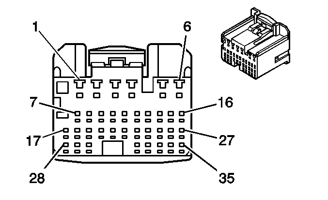
Connector Part Information |
| |||||
Pin | Wire Color | Function | ||||
1 | BLU | EVAP Canister Vent Solenoid Valve Control | ||||
2 | YEL/BLK | AC Compressor Clutch Relay Control | ||||
3 | -- | Not Used | ||||
4 | PNK/BLK | Heated Oxygen Sensor (HO2S) 2 Heater Circuit Control | ||||
5 | BLU/WHT | Auxiliary Intake Air Control Solenoid Control | ||||
6 | -- | Not Used | ||||
7 | LT GRN | Overdrive (OD) Indicator Control | ||||
8 | LT GRN/BLK | Park Neutral Position (PNP) Switch L Position Signal | ||||
9 | LT GRN | Park Neutral Position (PNP) Switch 2 Position Signal | ||||
10 | BLU | Park Neutral Position (PNP) Switch D Position Signal | ||||
11 | RED/BLK | Park Neutral Position (PNP) Switch R Position Signal | ||||
12-13 | -- | Not Used | ||||
14 | YEL/RED | Engine Coolant Temperature Gage Output | ||||
15-16 | -- | Not Used | ||||
17 | PPL/WHT | Vehicle Speed Sensor (VSS) Input | ||||
18 | RED/YEL | Overdrive (OD) Cut Signal, with Cruise Control* | ||||
19 | GRN/WHT | Brake Switch Signal | ||||
20-28 | -- | Not Used | ||||
29 | GRN/BLK | Overdrive (OD) Switch Signal* | ||||
30 | -- | Not Used | ||||
31 | YEL | AC Request Signal | ||||
32 | BLK/BLU | Evaporator Temperature Sensor Input | ||||
33 | GRN/WHT | AC On Signal | ||||
34-35 | -- | Not Used | ||||
| ||||||
|---|---|---|---|---|---|---|
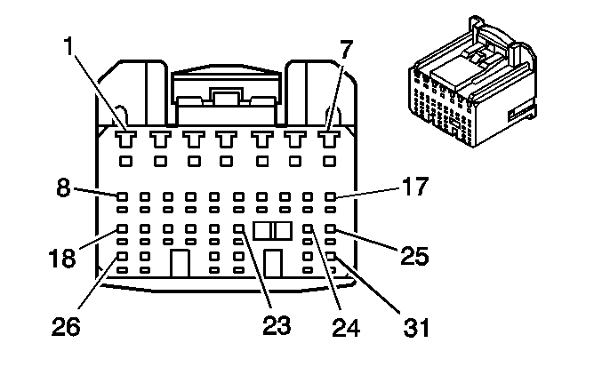
Connector Part Information |
| |||||
Pin | Wire Color | Function | ||||
1 | BLK | Ignition Positive Voltage | ||||
2 | -- | Not Used | ||||
3 | RED/WHT | Battery Voltage | ||||
4 | RED | EVAP Pressure Switching Solenoid Control | ||||
5 | BLK | Engine Speed Output for Tachometer | ||||
6 | GRN | Fan 1 Relay Control | ||||
7 | GRN/BLK | Fan 2 Relay Control | ||||
8 | BLK/WHT | EFI Relay Control High | ||||
9 | BLK/ORN | Ignition Positive Voltage | ||||
10 | GRN/RED | Circuit Opening Relay Control | ||||
11 | RED/YEL | MIL Control | ||||
12 | GRN | Electrical Load Idle-Up Signal, Tail Lamps | ||||
13 | WHT | Electrical Load Idle-Up Signal, Rear Defogger | ||||
14 | YEL | Supplemental Inflatable Restraint (SIR) System Signal | ||||
15 | -- | Not Used | ||||
16 | BLU/WHT | Cruise Control Idle | ||||
17 | -- | Not Used | ||||
18 | BLU/RED | Serial Data | ||||
19 | PNK | Data Link Connector (DLC) | ||||
20 | PNK/BLK | Diagnostic Request Circuit | ||||
21 | BLU | Fuel Tank Pressure (FTP) Sensor Input | ||||
22-31 | -- | Not Used | ||||

| ||||||
|---|---|---|---|---|---|---|
Connector Part Information |
| |||||
Pin | Wire Color | Function | ||||
1 | BLK | Sensor Ground | ||||
2 | WHT | VSS Input | ||||
| ||||||
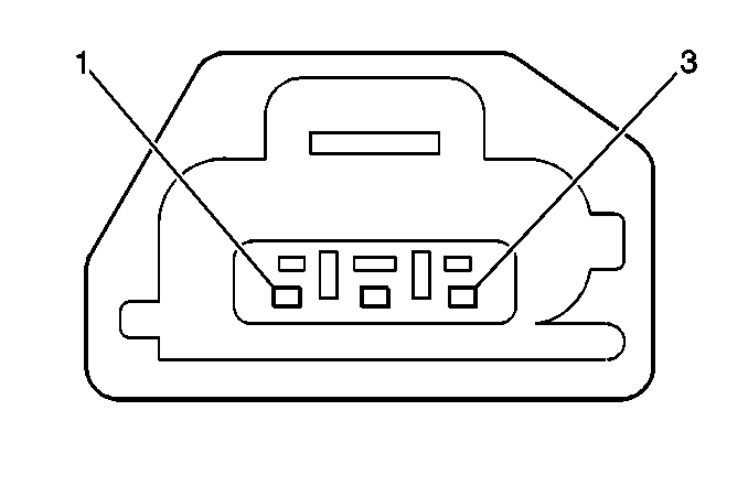
|---|---|---|---|---|---|---|
Connector Part Information |
| |||||
Pin | Wire Color | Function | ||||
1 | BRN | Sensor Ground | ||||
2 | YEL | Reference Voltage | ||||
3 | LT GRN | Throttle Position Input | ||||

| ||||||
|---|---|---|---|---|---|---|
Connector Part Information |
| |||||
Pin | Wire Color | Function | ||||
1 | GRN | Sensor Ground | ||||
2 | RED | VSS Input | ||||

| ||||||
|---|---|---|---|---|---|---|
Connector Part Information |
| |||||
Pin | Wire Color | Function | ||||
1 | BLK | Sensor Ground | ||||
2 | WHT | VSS Input | ||||
