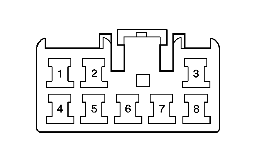
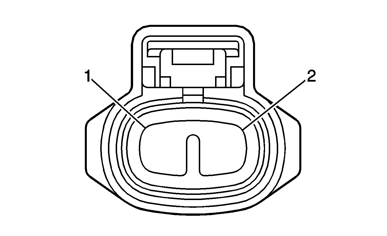
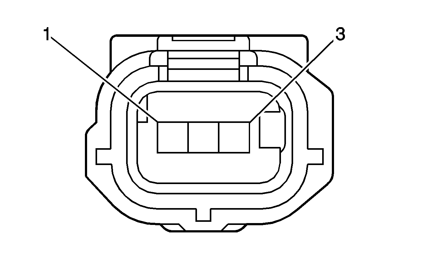
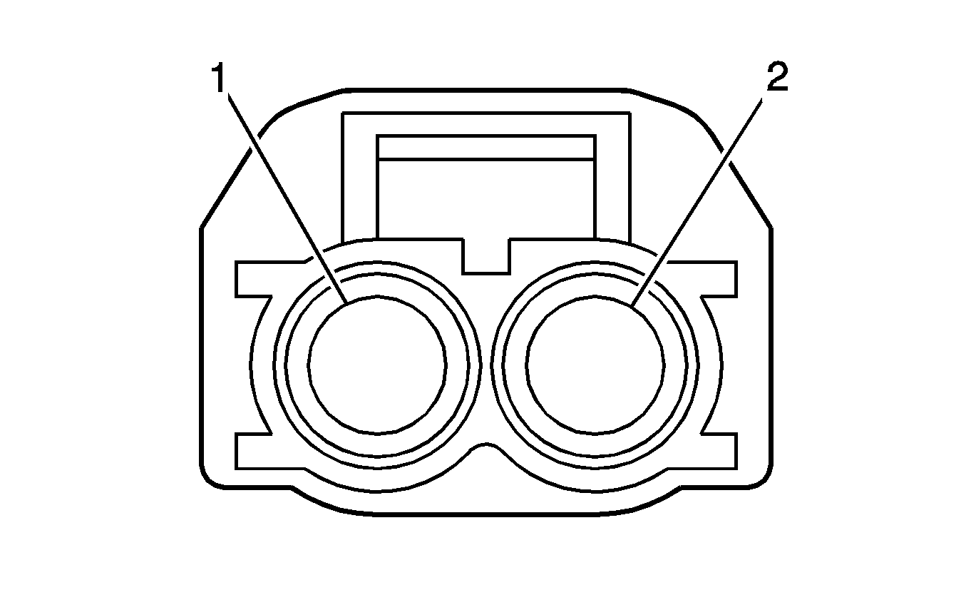
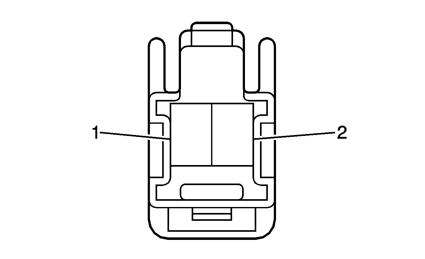
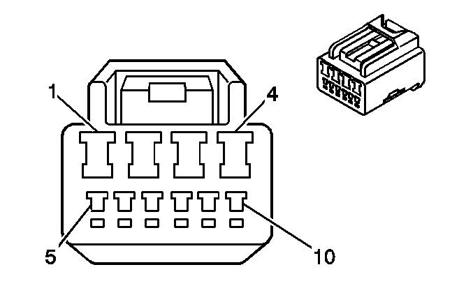
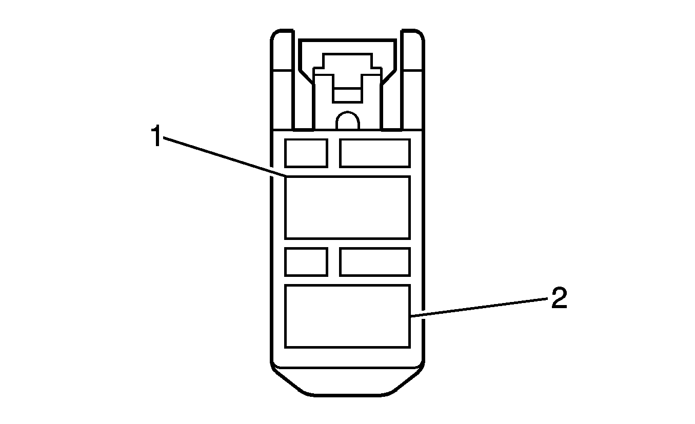
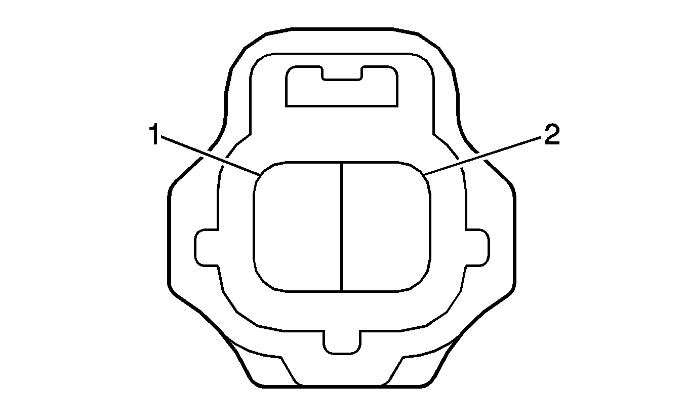
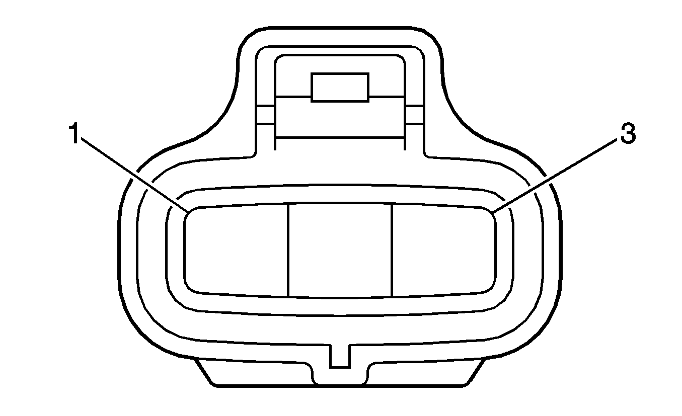
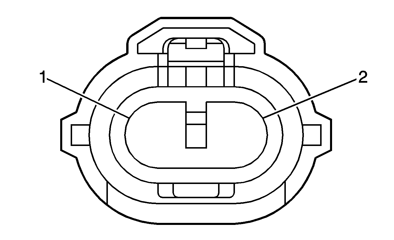
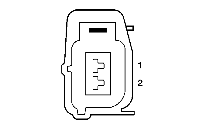
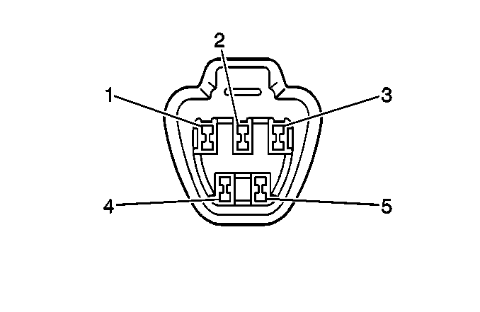
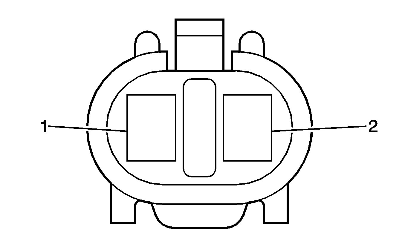
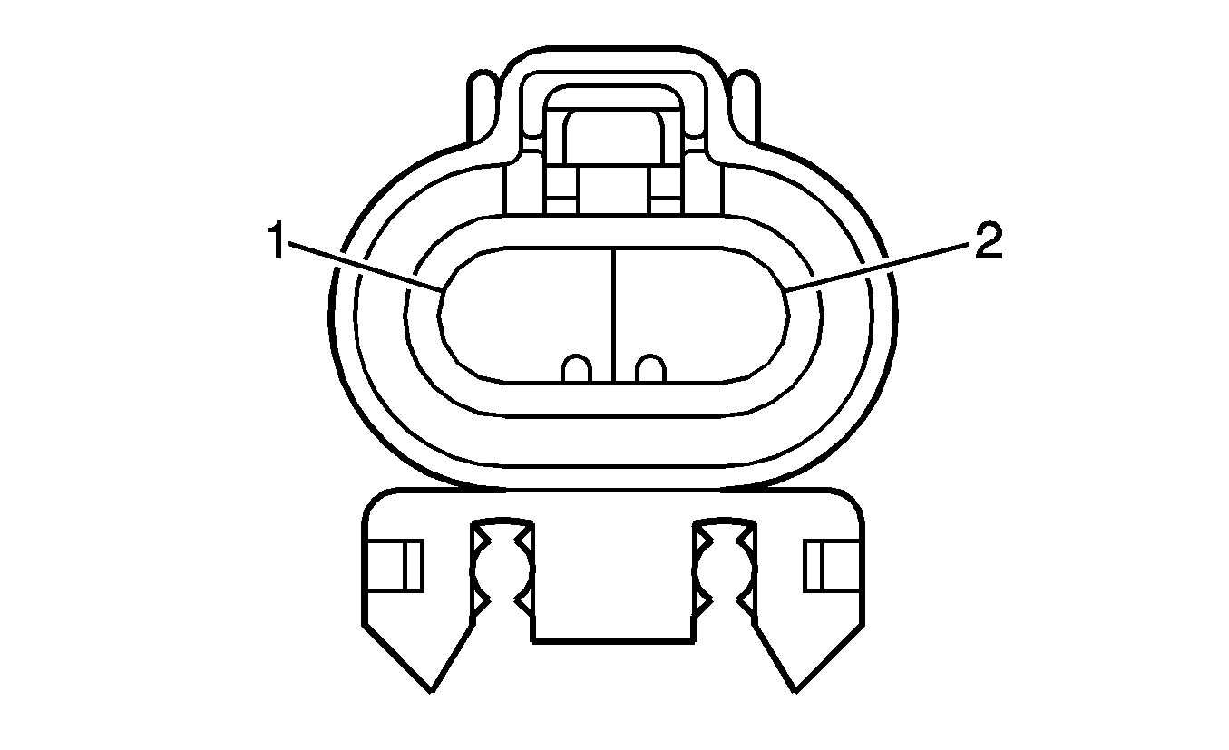
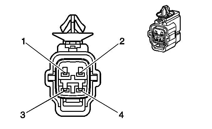
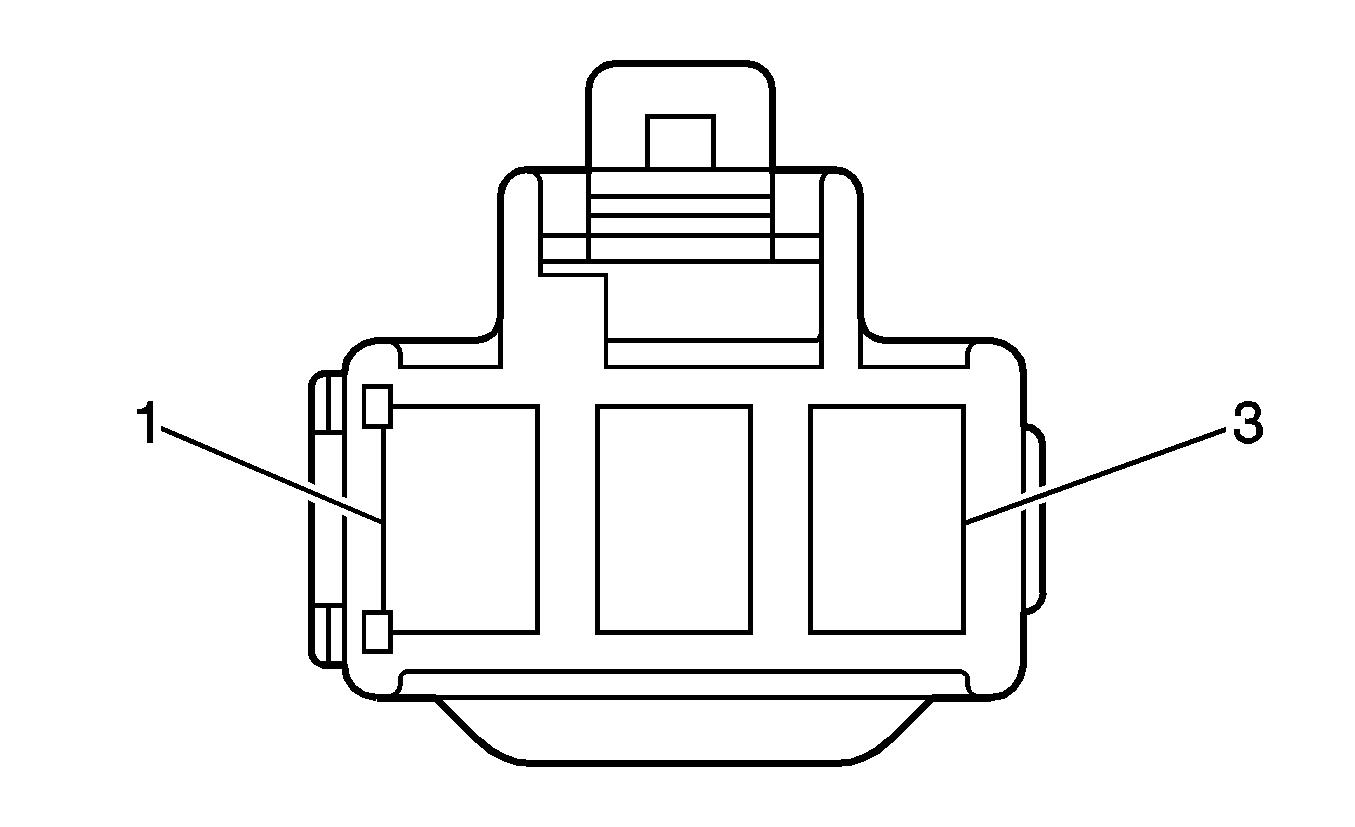
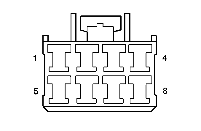
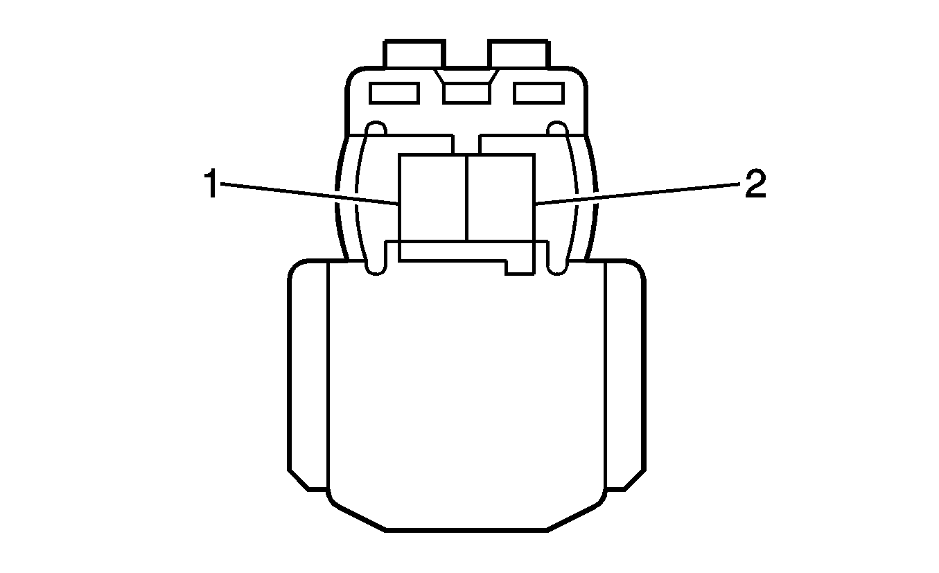
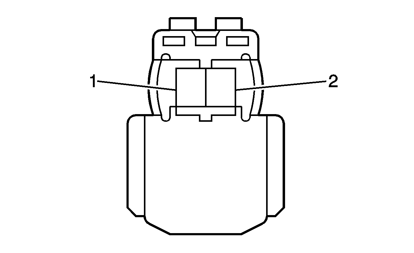
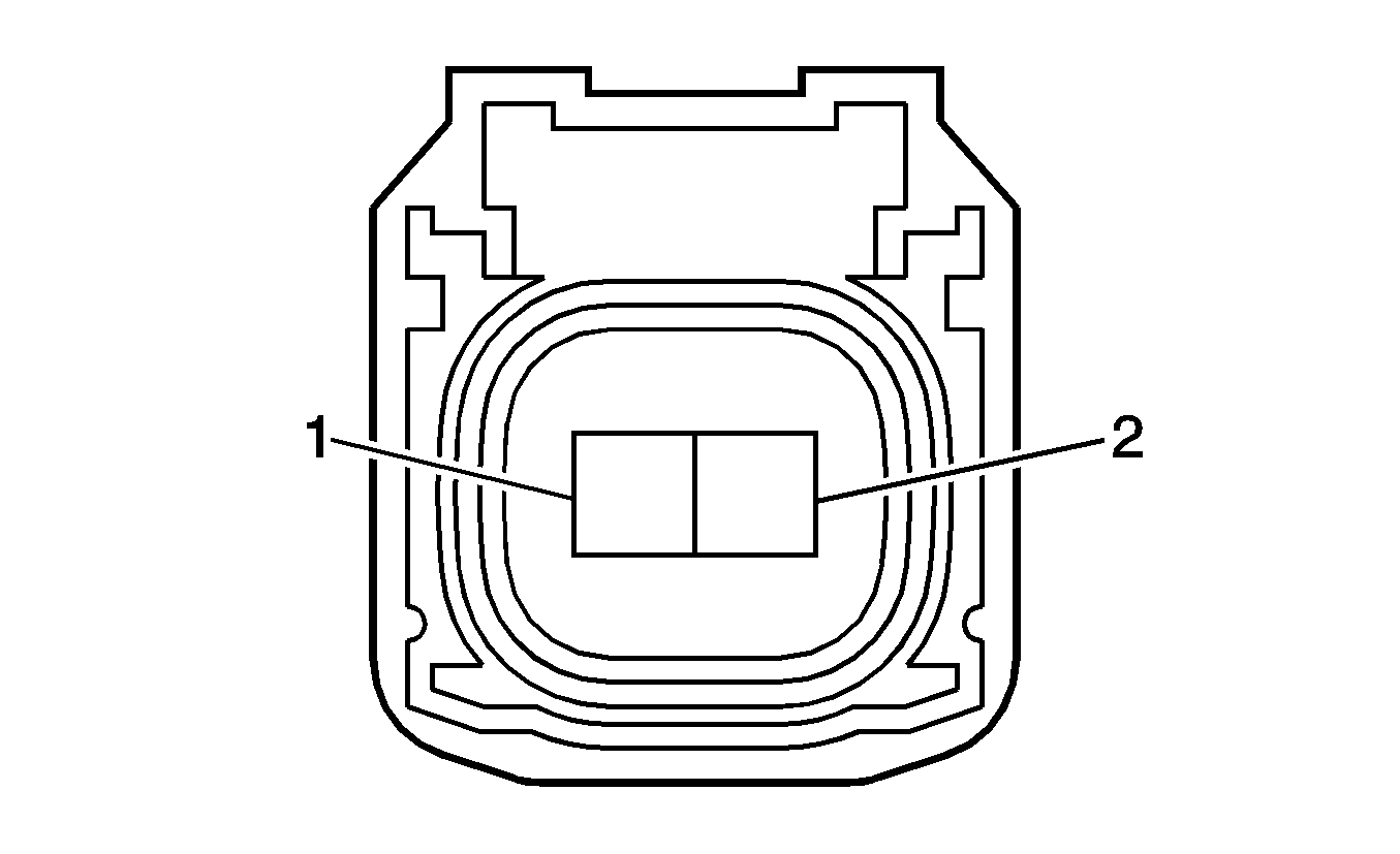
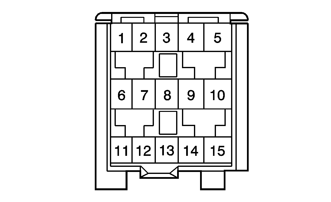
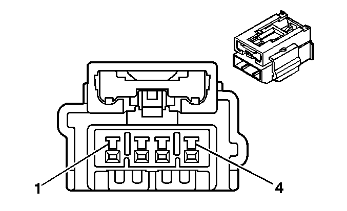
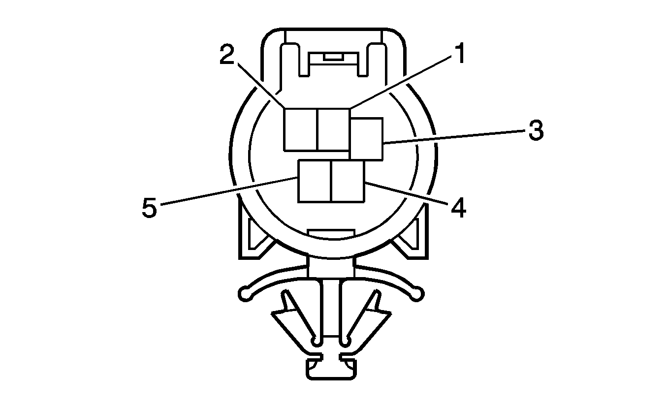
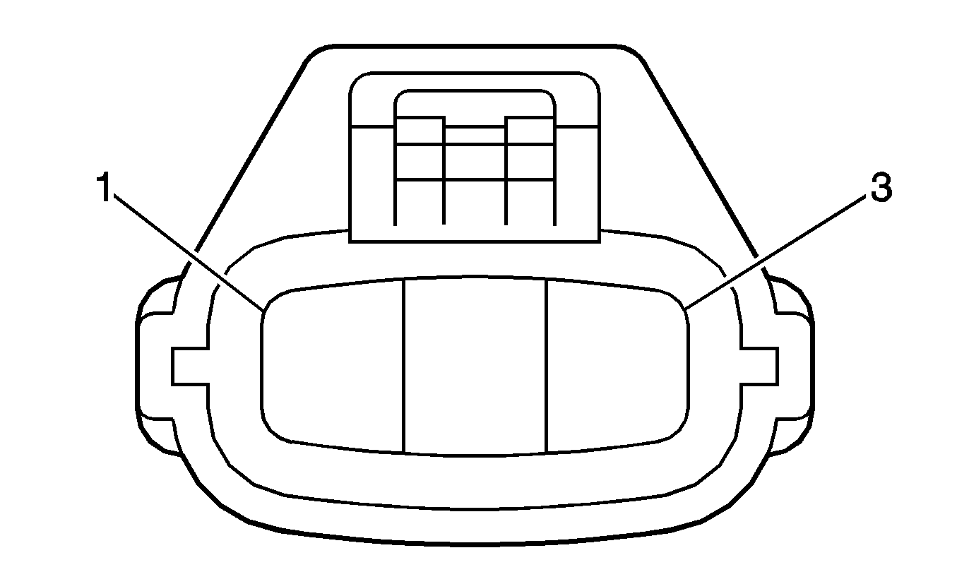
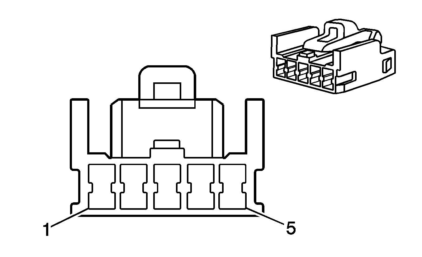
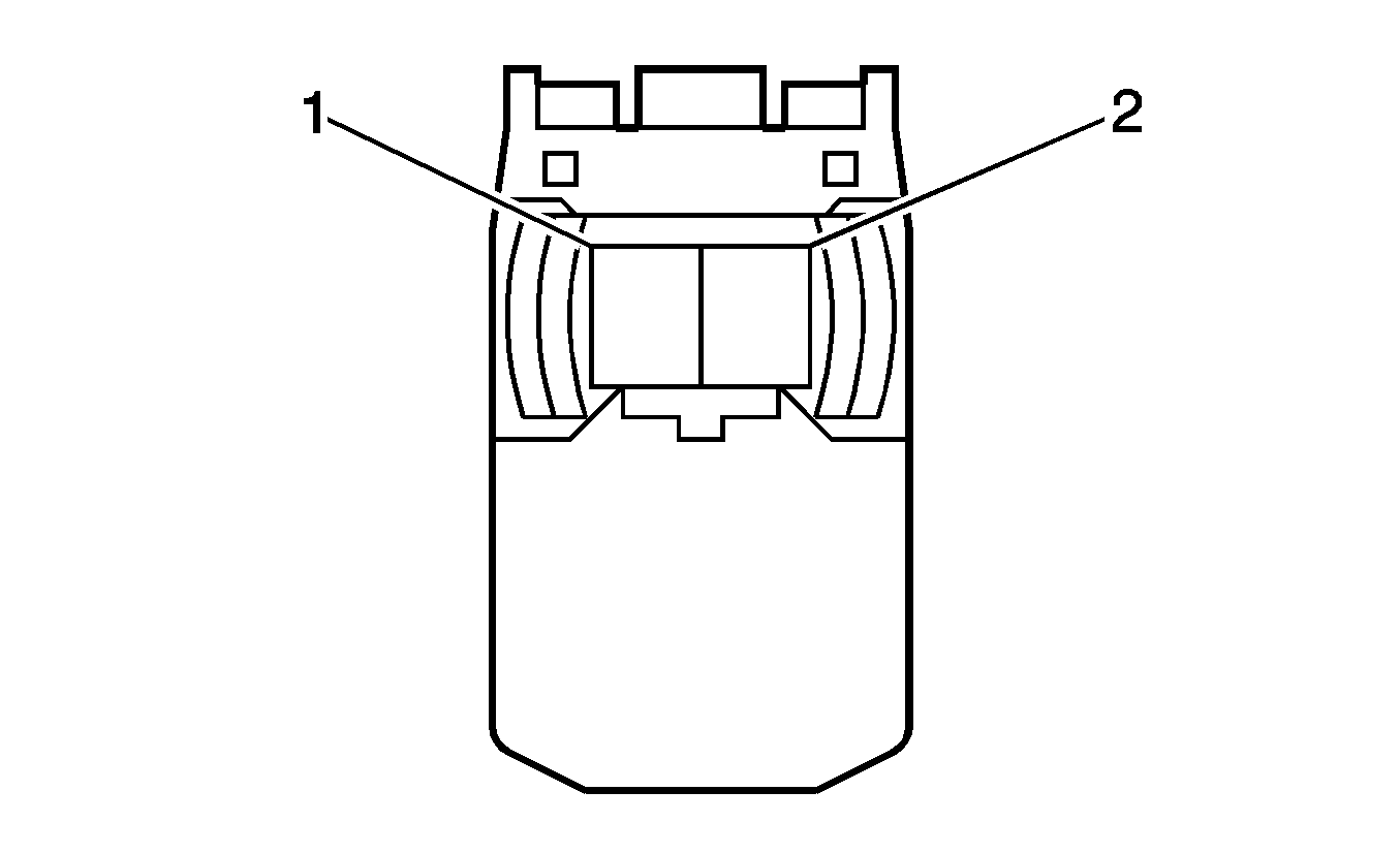
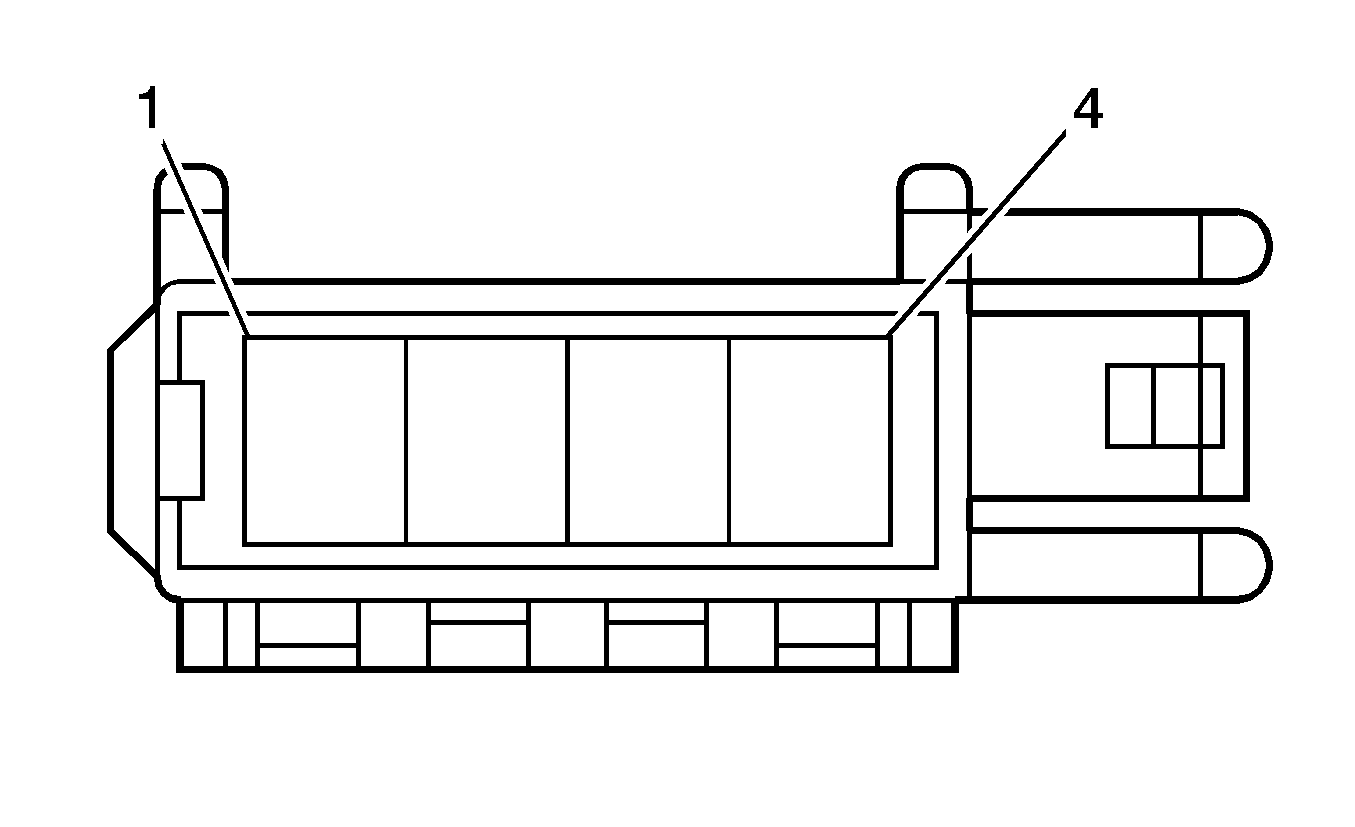
A/C Compressor Clutch
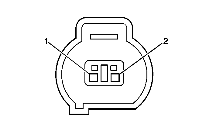
Connector Part Information
|
Pin | Wire | Circuit | Function |
|---|---|---|---|
1 | 0.5 WH/BK | -- | Ground |
2 | 0.5 L-GN | -- | A/C Compressor Clutch Supply Voltage |
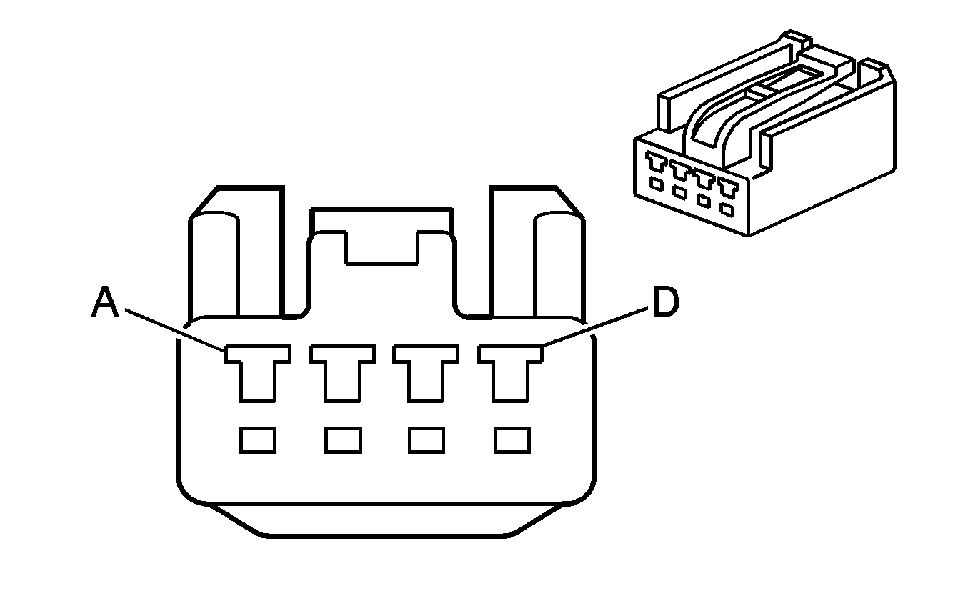
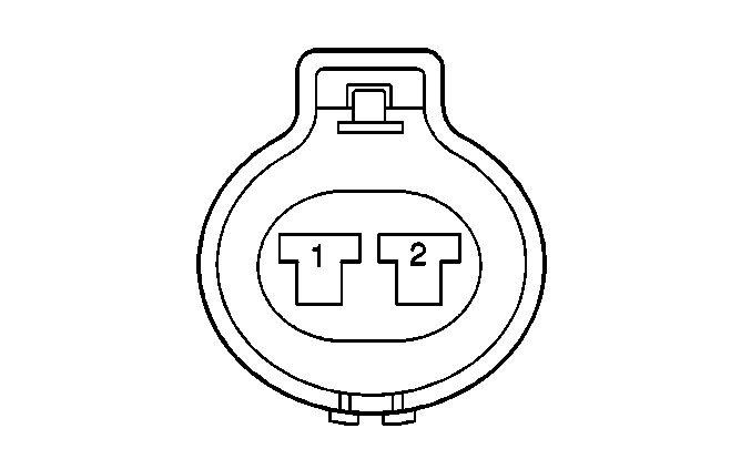
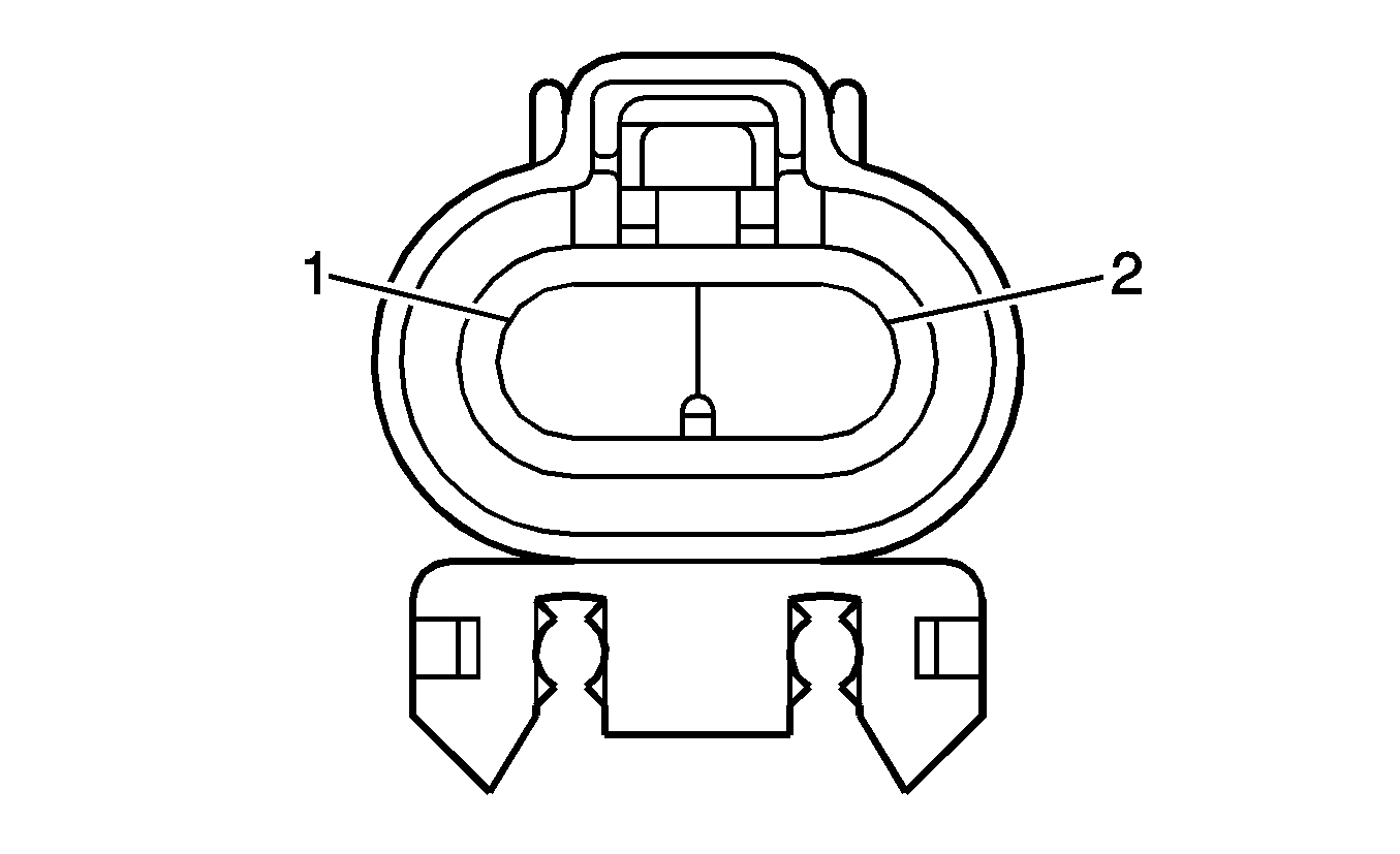
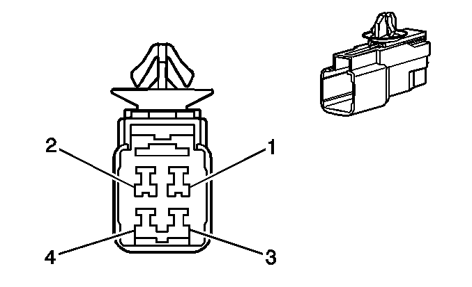
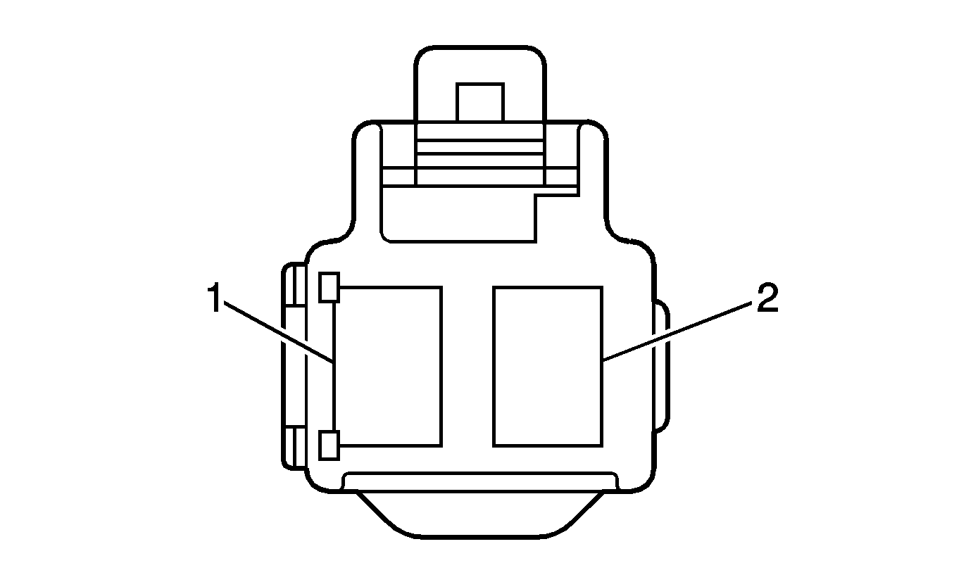
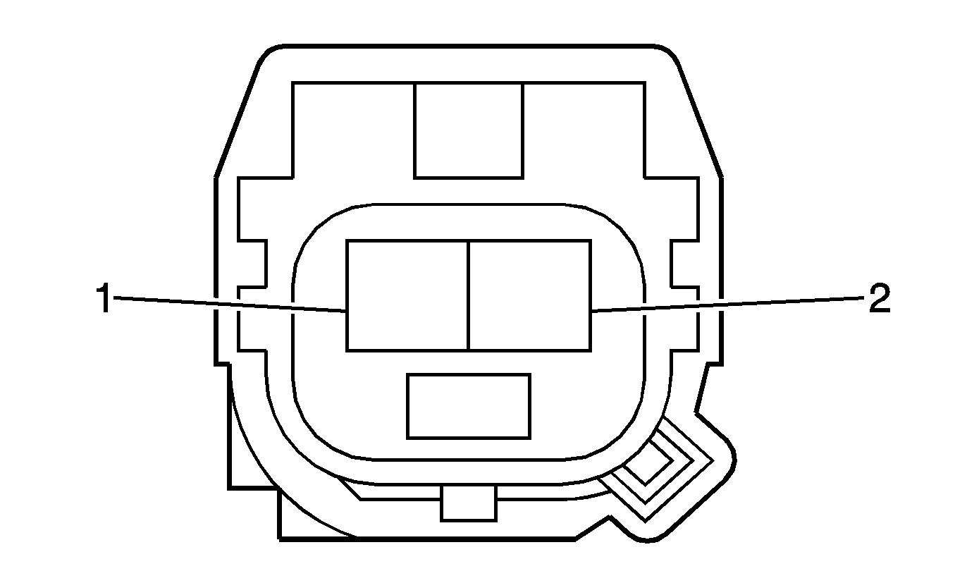
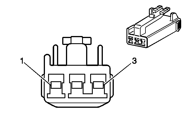
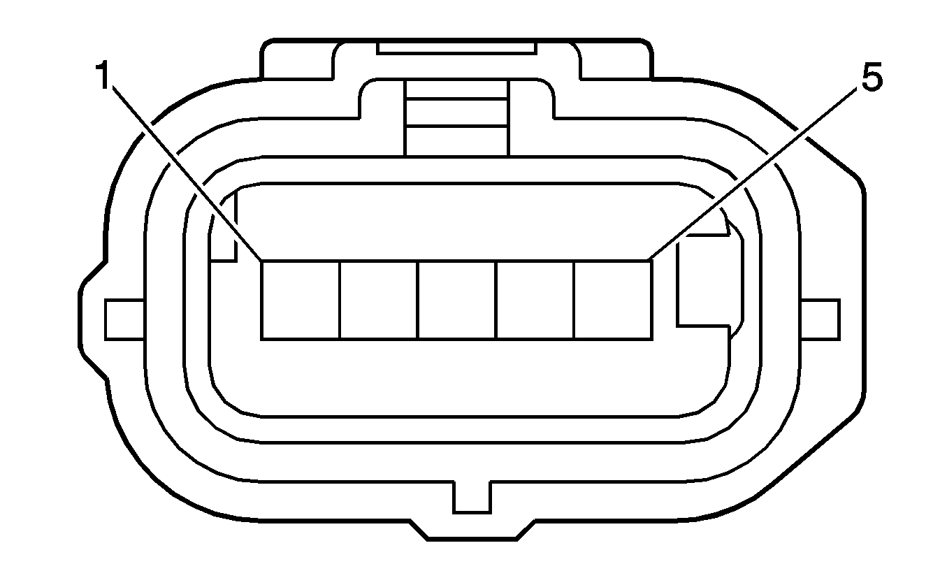
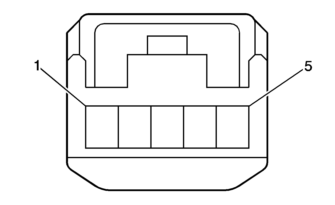
A/C Refrigerant Pressure Sensor
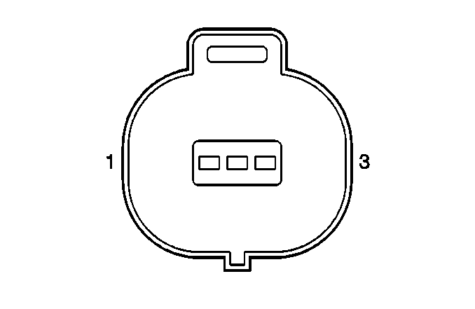
Connector Part Information
|
Pin | Wire | Circuit | Function |
|---|---|---|---|
1 | 0.3 D-GN | -- | Low Reference |
2 | 0.3 D-BU/WH | -- | A/C Refrigerant Pressure Sensor Signal |
3 | 0.3 BK | -- | 5-Volt Reference |
Accelerator Pedal Position (APP) Sensor
Connector Part Information
|
Pin | Wire | Circuit | Function |
|---|---|---|---|
1 | 0.3 BK | -- | APP Sensor 2 Signal |
2 | 0.3 OG | -- | Low Reference |
3 | 0.3 YE | -- | 5-Volt Reference |
4 | 0.3 PK | -- | APP Sensor 1 Signal |
5 | 0.3 RD | -- | Low Reference |
6 | 0.3 D-BU | -- | 5-Volt Reference |
Accessory AC/DC Power Control Module
Connector Part Information
|
Pin | Wire | Circuit | Function |
|---|---|---|---|
1-2 | -- | -- | Not Used |
3 | 0.35 BK | -- | Accessory Power Outlet Switch Control |
4 | 0.35 WH | -- | Instrument Panel Lamps Dimmer Switch - Output |
5 | 0.35 D-GN | -- | Battery Positive Voltage |
6 | 0.35 D-BU | -- | Battery Positive Voltage |
7 | 0.35 WH/BK | -- | Ground |
8 | -- | -- | Not Used |
Accessory Power Inverter Module
Connector Part Information
|
Pin | Wire | Circuit | Function |
|---|---|---|---|
1 | 0.75 RD | -- | Accessory Power Inverter module Supply Voltage |
2 | -- | -- | Not Used |
3 | 0.5 D-GN | -- | Accessory Power Inverter module Power |
4 | 0.5 WH/BK | -- | Ground |
5-6 | -- | -- | Not Used |
7 | 0.5 BK | -- | Accessory Power Inverter module Ground |
8 | -- | -- | Not Used |
Accessory Power Outlet - 110V AC

Connector Part Information
|
Pin | Wire | Circuit | Function |
|---|---|---|---|
1 | 0.5 D-GN | -- | Accessory Power Inverter Module Power |
2 | 0.5 BK | -- | Accessory Power Inverter Module Ground |
3-4 | -- | -- | Not Used |
5 | 0.5 WH/BK | -- | Ground |
6 | -- | -- | Not Used |
Ambient Air Temperature Sensor
Connector Part Information
|
Pin | Wire | Circuit | Function |
|---|---|---|---|
1 | 0.3 WH | -- | Ambient Air Temperature Sensor Signal |
2 | 0.3 D-GN | -- | Low Reference |
Ambient Light Sensor

Connector Part Information
|
Pin | Wire | Circuit | Function |
|---|---|---|---|
1 | 0.35 GY | -- | Ambient Light Sensor - Power |
2 | -- | -- | -- |
3 | 0.35 GN | -- | Ground |
4 | 0.35 L-BU | -- | Ambient Light Sensor Signal |
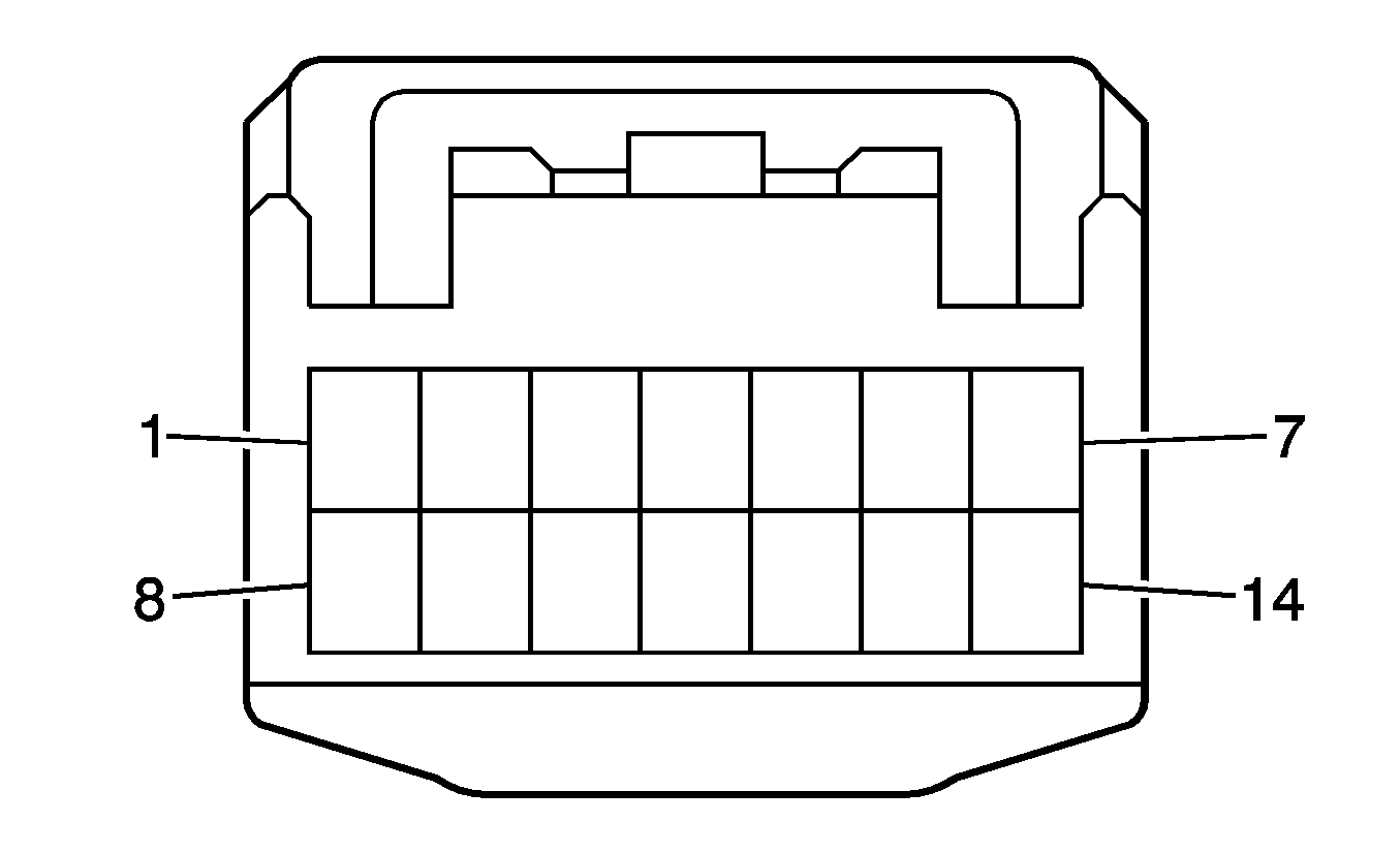
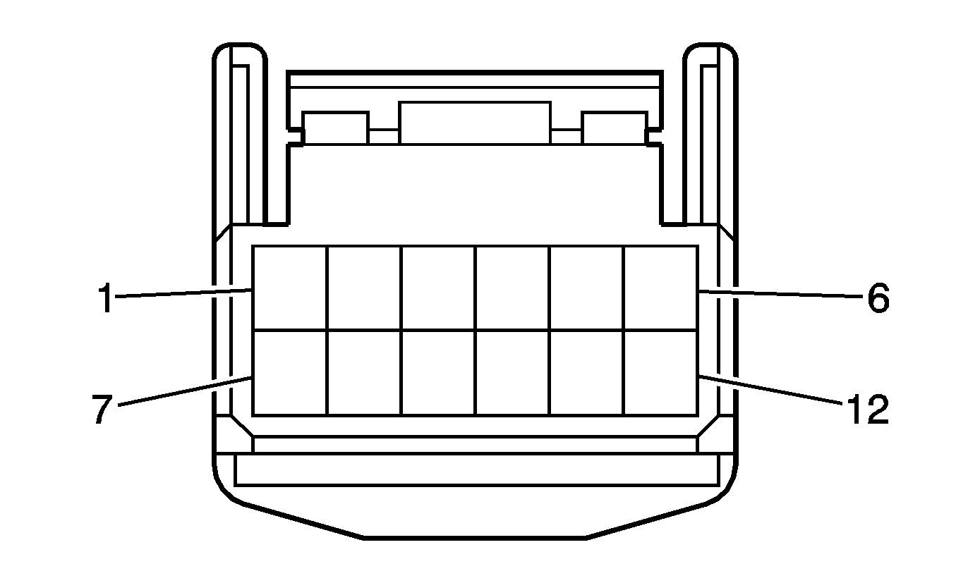
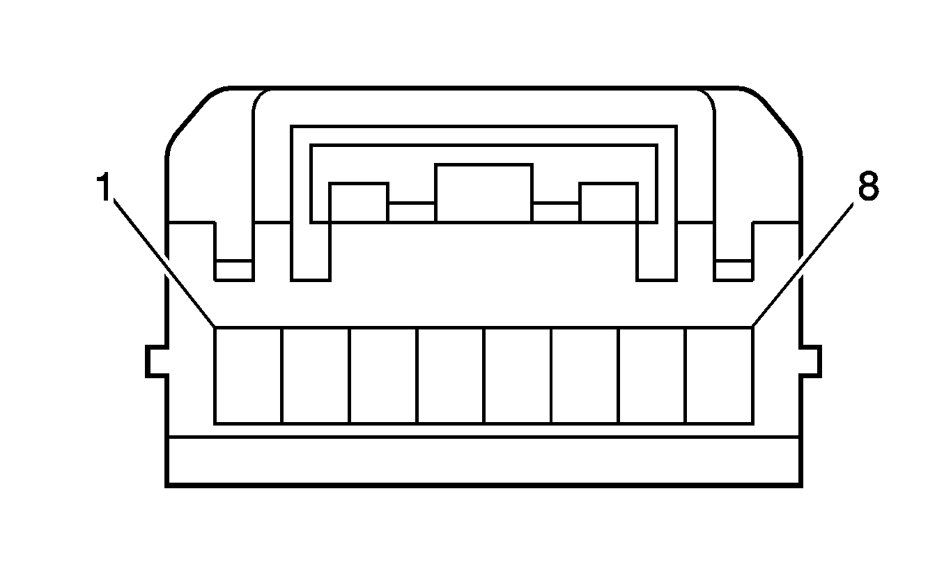
Audio Amplifier X1 (U65)
Connector Part Information
|
Pin | Wire | Circuit | Function |
|---|---|---|---|
1 | 0.35 YE | -- | Amplifier Signal |
2 | -- | -- | Not Used |
3 | 0.35 BG | -- | Antenna Signal |
4 | 0.35 BK | -- | Left Rear Speaker (+) |
5 | 0.35 D-GN | -- | Left Rear Speaker (-) |
6 | 0.35 D-GN | -- | Left Front Tweeter (-) |
7 | 0.35 BK | -- | Left Front Tweeter (+) |
8 | 0.35 L-GN | -- | Mute |
9 | 1.25 RD | -- | Right Rear Speaker Output (+) |
10 | 1.25 WH | -- | Right Rear Speaker Output (-) |
11 | 1.25 BK | -- | Left Rear Speaker Output (+) |
12 | 1.25 YE | -- | Left Rear Speaker Output (-) |
13 | 1.25 D-BU | -- | Rear Subwoofer Speaker Output (-) |
14 | 1.25 L-GN | -- | Rear Subwoofer Speaker Output (+) |
15 | -- | -- | Not Used |
16 | 0.35 WH | -- | Right Rear Speaker (-) |
17 | 0.35 RD | -- | Right Rear Speaker (+) |
18 | 0.35 RD | -- | Right Front Tweeter (+) |
19 | 0.35 WH | -- | Right Front Tweeter (-) |
20 | -- | -- | Not Used |
21 | 1.25 WH | -- | Left Front Tweeter Output (+) |
22 | 1.25 RD | -- | Left Front Tweeter Output (-) |
23 | 1.25 BN | -- | Right Front Tweeter Output (+) |
24 | 1.25 PK | -- | Right Front Tweeter Output (-) |
Audio Amplifier X2 (U65)
Connector Part Information
|
Pin | Wire | Circuit | Function |
|---|---|---|---|
1 | 1.25 BK | -- | Rear Subwoofer Speaker Output (-) |
2 | 1.25 YE | -- | Rear Subwoofer Speaker Output (+) |
3 | 2.00 WH/BK | -- | Ground |
4 | 2.00 RD | -- | Battery Positive Voltage |
5 | 1.25 L-GN | -- | Right Front Speaker Output (+) |
6 | 1.25 D-BU | -- | Right Front Speaker Output (-) |
7 | 1.25 VT | -- | Left Front Speaker Output (-) |
8 | 1.25 PK | -- | Left Front Speaker Output (+) |
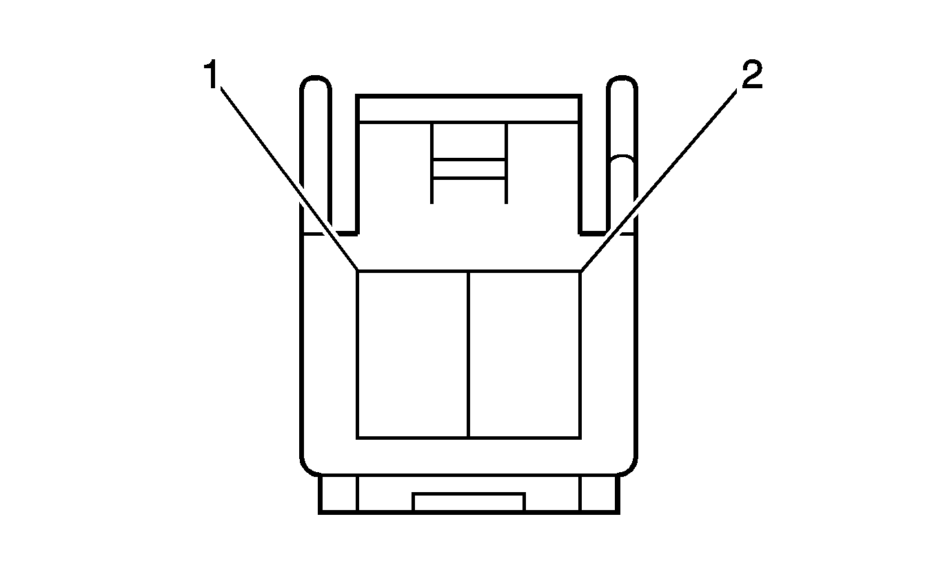
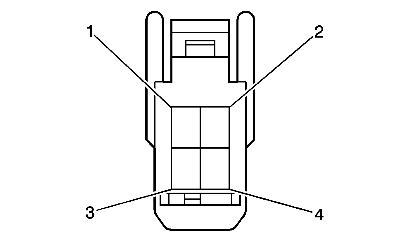
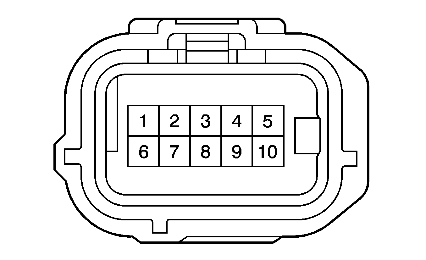
Automatic Transmission Input Shaft Speed (ISS) Sensor
Connector Part Information
|
Pin | Wire | Circuit | Function |
|---|---|---|---|
1 | 0.5 BK | -- | -- |
2 | 0.5 YE | -- | -- |
Automatic Transmission Output Shaft Speed (OSS) Sensor
Connector Part Information
|
Pin | Wire | Circuit | Function |
|---|---|---|---|
1 | 0.5 WH | -- | Intermediate Shaft Speed Sensor - Low Signal |
2 | 0.5 RD | -- | Intermediate Shaft Speed Sensor - High Signal |
Automatic Transmission Shift Lever
Connector Part Information
|
Pin | Wire | Circuit | Function |
|---|---|---|---|
1 | 0.35 VT | -- | Shift Lock Relay (+) |
2 | 0.35 BG | -- | Shift Lock Relay (-) |
3 | -- | -- | Not Used |
4 | 0.35 BK | -- | Shift Switch Tap Down Signal |
5 | 0.35 L-GN | -- | Shift Switch Tap Up Signal |
6 | 0.35 D-BU | -- | Ignition 1 Voltage |
7-10 | -- | -- | Not Used |
11 | 0.35 WH/BK | -- | Ground |
12 | -- | -- | Not Used |
13 | 0.35 WH | -- | PNP Switch Low Signal |
14 | -- | -- | Not Used |
Automatic Transmission Shift Lever Position Indicator
Connector Part Information
|
Pin | Wire | Circuit | Function |
|---|---|---|---|
1 | 0.35 L-GN | -- | Instrument Panel Lamps Dimming Low Control |
2 | 0.35 WH | -- | Instrument Panel Lamps Dimming Voltage |
Automatic Transmission Shift Lock Control Solenoid
Connector Part Information
|
Pin | Wire | Circuit | Function |
|---|---|---|---|
1 | 0.35 WH/BK | -- | Ground |
2 | -- | -- | Not Used |
3 | -- | -- | Not Used |
4 | 0.35 D-BU | -- | Stop Lamp Switch Signal |
5 | 0.35 YE | -- | Ignition Lock Cylinder Solenoid Control |
6 | 0.35 GY | -- | Ignition Switch Signal - Start |
7 | -- | -- | Not Used |
8 | 0.35 D-BU | -- | Ignition 1 Voltage |
Backup Lamp Switch (LAY)
Connector Part Information
|
Pin | Wire | Circuit | Function |
|---|---|---|---|
1 | 0.5 RD | -- | Back-up Lamp - Feed |
2 | 0.5 D-GN | -- | Battery Positive Voltage |
Backup Lamp Switch (LAX)
Connector Part Information
|
Pin | Wire | Circuit | Function |
|---|---|---|---|
1 | 0.5 RD | -- | Back-up Lamp - Feed |
2 | 0.5 D-GN | -- | Battery Positive Voltage |
Blower Motor
Connector Part Information
|
Pin | Wire | Circuit | Function |
|---|---|---|---|
1 | 3.0 D-BU | -- | Blower Motor High Control |
2 | 3.0 BN | -- | Blower Motor Control |
Blower Motor Resistor
Connector Part Information
|
Pin | Wire | Circuit | Function |
|---|---|---|---|
1 | 3.0 D-BU | -- | Blower Motor High Control |
2 | 2.0 BK | -- | Medium 1 Blower Motor Control |
3 | 2.0 YE | -- | Medium 2 Blower Motor Control |
4 | 2.0 WH/BK | -- | Ground |
Blower Motor Switch
Connector Part Information
|
Pin | Wire | Circuit | Function |
|---|---|---|---|
1 | 0.5 WH | -- | Instrument panel lamps Dimmer Switch - Output |
2 | 0.35 BG | -- | Defroster Relay Control |
3 | 0.35 RD | -- | Ignition 1 Voltage |
4 | 0.35 GY | -- | Blower Motor Low Control |
5 | 3.0 WH/BK | -- | Ground |
6 | 3.0 D-BU | -- | Blower Motor High Control |
7 | 0.35 D-GN | -- | Battery Positive Voltage |
8 | -- | -- | Not Used |
9 | 2.0 BK | -- | Medium 1 Blower Motor Control |
10 | 2.0 YE | -- | Medium 2 Blower Motor Control |
Body Control Module (BCM)
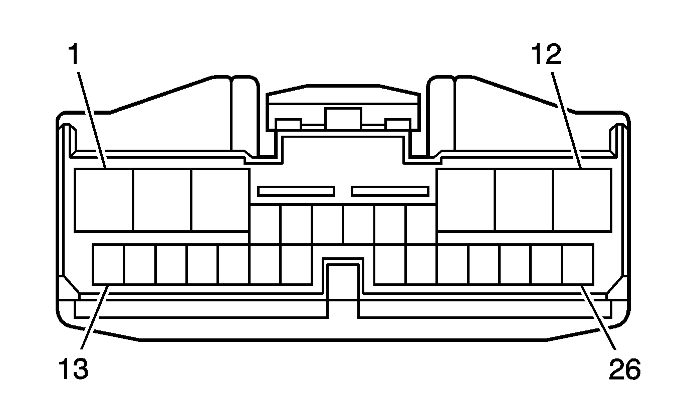
Connector Part Information
|
Pin | Wire | Circuit | Function |
|---|---|---|---|
1 | -- | -- | Not Used |
2 | 1.25 D-GN | -- | Driver Door Lock Motor Unlock Control |
3 | 0.35 VT | -- | Headlamp Relay Control |
4 | -- | -- | Not Used |
5 | 0.5 RD | -- | Passenger Door Lock Position Switch Input |
6-12 | -- | -- | Not Used |
13 | 0.35 BK | -- | Left Rear Door Ajar Switch Signal |
14 | 0.35 PK | -- | Driver Door Key Switch Unlock Signal |
15 | -- | -- | Not Used |
16 | 0.22 VT | -- | Serial Data |
17 | 0.22 L-BU | -- | Keyless Entry Program Enable Signal |
18 | 0.35 L-GN | -- | Data Communication (-) |
19 | 0.35 WH | -- | Data Communication (+) |
20 | -- | -- | Not Used |
21 | 0.35 YE | -- | Driver Door Lock Position Switch Input |
22 | 0.35 WH | -- | High Speed GMLAN Serial Data Bus- |
23 | 0.35 RD | -- | High Speed GMLAN Serial Data Bus+ |
24 | 0.35 D-GN | -- | Rear Door Lock Position Switch Input |
25-26 | -- | -- | Not Used |
Brake Fluid Level Switch
Connector Part Information
|
Pin | Wire | Circuit | Function |
|---|---|---|---|
1 | 0.5 YE | -- | Brake Fluid level Sensor Signal |
2 | 0.5 WH/BK | -- | Ground |
Camshaft Position (CMP) Actuator Solenoid Valve - Bank 2 Exhaust (LAY)
Connector Part Information
|
Pin | Wire | Circuit | Function |
|---|---|---|---|
1 | 0.5 BN/BK | -- | Cam Phaser Control - Bank 1 Exhaust |
2 | 0.5 PK | -- | Low Reference |
Camshaft Position (CMP) Actuator Solenoid Valve - Bank 2 Intake (LAY)
Connector Part Information
|
Pin | Wire | Circuit | Function |
|---|---|---|---|
1 | 0.5 BK | -- | Cam Phaser Control - Bank 1 Intake |
2 | 0.5 VT/YE | -- | Low Reference |
Camshaft Position (CMP) Actuator Solenoid Valve - Bank 2 Intake (LAX)
Connector Part Information
|
Pin | Wire | Circuit | Function |
|---|---|---|---|
1 | 0.5 BK | -- | Cam Phaser Control |
2 | 0.5 VT | -- | Low Reference |
Camshaft Position (CMP) Sensor (LAX)
Connector Part Information
|
Pin | Wire | Circuit | Function |
|---|---|---|---|
1 | 0.5 RD | -- | CMP Sensor High Signal |
2 | 0.5 WH | -- | CMP Sensor Low Signal |
Camshaft Position (CMP) Sensor - Bank 2 Exhaust (LAY)
Connector Part Information
|
Pin | Wire | Circuit | Function |
|---|---|---|---|
1 | 0.5 RD | -- | 5-Volt Reference |
2 | 0.5 WH | -- | Low Reference |
3 | 0.5 BN/RD | -- | Camshaft Sensor Signal |
Camshaft Position (CMP) Sensor - Bank 2 Intake (LAY)
Connector Part Information
|
Pin | Wire | Circuit | Function |
|---|---|---|---|
1 | 0.5 RD | -- | 5-Volt Reference |
2 | 0.5 WH | -- | Low Reference |
3 | 0.5 BN/RD | -- | Camshaft Sensor Signal |
Center High Mounted Stop Lamp (CHMSL)
Connector Part Information
|
Pin | Wire | Circuit | Function |
|---|---|---|---|
1 | 0.5 BU | -- | Stop Lamp Supply Voltage |
2 | 0.5 WH/BK | -- | Ground |
Cigar Lighter
Connector Part Information
|
Pin | Wire | Circuit | Function |
|---|---|---|---|
1 | 0.75 GY | -- | Ignition Voltage |
2 | 0.75 WH/BK | -- | Ground |
Cigar Lighter Illumination Lamp

Connector Part Information
|
Pin | Wire | Circuit | Function |
|---|---|---|---|
1 | 0.35 WH | -- | Instrument Panel Lamps Dimming Low Control |
2 | 0.35 D-GN | -- | Instrument Panel Lamps Dimming Voltage |
Clutch Start Switch

Connector Part Information
|
Pin | Wire | Circuit | Function |
|---|---|---|---|
1 | 0.5 L-GN | -- | Ignition 1 Voltage |
2 | 0.5 WH | -- | Ignition Voltage |
Courtesy/Reading Lamps - 2nd Row
Connector Part Information
|
Pin | Wire | Circuit | Function |
|---|---|---|---|
1 | 0.35 PK | -- | Battery positive Voltage |
2 | 0.35 GY | -- | Courtesy Lamp Control |
3 | 0.35 WH/BK | -- | Ground |
Courtesy/Reading Lamps - 3rd Row
Connector Part Information
|
Pin | Wire | Circuit | Function |
|---|---|---|---|
1 | 0.35 PK | -- | Battery positive Voltage |
2 | 0.35 GY | -- | Courtesy Lamp Control |
3 | 0.35 WH/BK | -- | Ground |
Crankshaft Position (CKP) Sensor (LAX)
Connector Part Information
|
Pin | Wire | Circuit | Function |
|---|---|---|---|
1 | 0.3 RD | -- | CKP Sensor High |
2 | 0.3 D-GN | -- | CKP Sensor Low |
Crankshaft Position (CKP) Sensor (LAY)
Connector Part Information
|
Pin | Wire | Circuit | Function |
|---|---|---|---|
1 | 0.3 RD | -- | CKP Sensor High |
2 | 0.3 D-GN | -- | CKP Sensor Low |
Cruise Control Switch
Connector Part Information
|
Pin | Wire | Circuit | Function |
|---|---|---|---|
1-2 | -- | -- | Not Used |
3 | RD | -- | Cruise Control Switch Signal |
4 | BK | -- | Ground |
Daytime Running Lights (DRL) Module
Connector Part Information
|
Pin | Wire | Circuit | Function |
|---|---|---|---|
A | 3.0 BN | -- | High Beam Headlamps Ground |
B | 3.0 WH/BK | -- | Ground |
1 | 0.35 RD | -- | Battery Positive Voltage |
2 | 0.35 WH | -- | Fog Lamp Switch Signal |
3 | 0.35 GY | -- | DRL Indication Control |
4 | 0.35 VT | -- | Headlamp Relay Control |
5 | 0.35 D-GN | -- | Park Lamp Switch Signal |
6 | 0.35 YE | -- | Low Battery Indication Signal |
7 | 0.35 WH/BK | -- | Ground |
8 | 0.35 BK | -- | Parklamp/Headlamp Signal |
9 | 0.35 BG | -- | Park Brake Switch Signal |
10 | 0.35 D-BU | -- | Ignition 1 Voltage |
11 | 0.22 PK | -- | Dimmer Relay Control |
12 | 0.35 L-BU | -- | Park Lamp Relay - Ground |
13 | 0.35 BN | -- | Park Lamp Relay Control |
14 | 0.35 L-GN | -- | High Beam Signal |
15 | 0.35 D-BU | -- | Headlamp Indicator Control |
16 | 0.35 D-GN | -- | Ground |
17 | 0.35 L-BU | -- | Ambient Light Sensor Signal |
18 | 0.35 GY | -- | Ambient Light Sensor Power |
Data Link Connector (DLC)
Connector Part Information
|
Pin | Wire | Circuit | Function |
|---|---|---|---|
1 | 0.35 YE | -- | Low Speed GMLAN Serial Data |
2-3 | -- | -- | Not Used |
4 | 0.35 WH/BK | -- | Ground |
5 | 0.35 BN | -- | Ground |
6 | 0.35 L-GN | -- | High Speed GMLAN Serial Data Bus+ |
7 | 0.35 WH | -- | Low Speed Serial Data |
8 | -- | -- | Not Used |
9 | 0.35 GY | -- | Low Speed Serial Data |
10-11 | -- | -- | Not Used |
12 | 0.35 RD | -- | Brake Pressure Modulator Valve Signal |
13 | 0.35 D-GN | -- | Low Speed Serial Data |
14 | 0.35 WH | -- | High Speed GMLAN Serial Data Bus+ |
15 | -- | -- | Not Used |
16 | 0.35 L-GN | -- | Battery Positive Voltage |
Digital Radio Receiver
Connector Part Information
|
Pin | Wire | Circuit | Function |
|---|---|---|---|
1-3 | -- | -- | Not Used |
4 | 0.35 BG | -- | TMX + |
5 | 0.35 WH | -- | Audio Signal Right (-) |
6 | 0.35 BK | -- | Audio Signal Right (+) |
7 | 0.35 RD | -- | Audio Signal Left (+) |
8 | 0.35 D-GN | -- | Audio Signal Left (-) |
9 | 0.35 L-BU | -- | Battery Positive Voltage |
10-13 | -- | -- | Not Used |
14 | 0.01 BARE | -- | Drain Wire |
15 | -- | -- | Not Used |
16 | 0.5 BN | -- | Ground |
Dome/Courtesy Reading Lamps (CF5)
Connector Part Information
|
Pin | Wire | Circuit | Function |
|---|---|---|---|
1 | 0.35 GY | -- | Courtesy Lamp Control |
2 | 0.35 D-BU | -- | Sunroof Switch Close Signal |
3 | 0.35 RD | -- | Sunroof Switch Vent Signal |
4 | 0.35 D-GN | -- | Sunroof Switch Open Signal |
5 | -- | -- | Not Used |
6 | 0.35 PK | -- | Battery Positive Voltage |
7 | 0.35 WH/BK | -- | Ground |
8-12 | -- | -- | Not Used |
Dome/Courtesy Reading Lamps (without CF5)
Connector Part Information
|
Pin | Wire | Circuit | Function |
|---|---|---|---|
1 | 0.35 PK | -- | Battery Positive Voltage |
2 | 0.35 WH/BK | -- | Ground |
Door Jamb Switch - Driver
Connector Part Information
|
Pin | Wire | Circuit | Function |
|---|---|---|---|
1 | 0.5 VT | -- | Driver Door Ajar Switch Signal |
Door Jamb Switch - Left Rear
Connector Part Information
|
Pin | Wire | Circuit | Function |
|---|---|---|---|
1 | 0.5 GY | -- | Left Rear Door Ajar Switch Signal |
Door Jamb Switch - Passenger
Connector Part Information
|
Pin | Wire | Circuit | Function |
|---|---|---|---|
1 | 0.5 BG | -- | Front Passenger Door Ajar Switch Signal |
Door Jamb Switch - Right Rear
Connector Part Information
|
Pin | Wire | Circuit | Function |
|---|---|---|---|
1 | 0.5 YE | -- | Right Rear Door Ajar Switch Signal |
Door Lock Actuator - Driver
Connector Part Information
|
Pin | Wire | Circuit | Function |
|---|---|---|---|
1 | 1.25 D-GN | -- | Driver Door Lock Motor Unlock Control |
2-3 | -- | -- | Not Used |
4 | 1.25 BG | -- | Driver Door Lock Motor Lock Control |
5-6 | -- | -- | Not Used |
7 | 0.35 WH/BK | -- | Ground |
8 | 0.35 YE | -- | Driver Door Lock Position Switch Input |
9 | 0.35 BK | -- | Driver Door Key Switch Lock Signal |
10 | 0.35 PK | -- | Driver Door Key Switch Unlock Signal |
Door Lock Actuator - Left Rear
Connector Part Information
|
Pin | Wire | Circuit | Function |
|---|---|---|---|
1 | 1.25 D-GN | -- | Left Rear Door Lock Motor Unlock Control |
2-3 | -- | -- | Not Used |
4 | 1.25 BG | -- | Left Rear Door Lock Motor Lock Control |
5 | -- | -- | Not Used |
6 | 0.35 D-GN | -- | Right Rear Door Lock Position Switch Input |
7-8 | -- | -- | Not Used |
9 | 0.35 WH/BK | -- | Ground |
10 | -- | -- | Not Used |
Door Lock Actuator - Passenger
Connector Part Information
|
Pin | Wire | Circuit | Function |
|---|---|---|---|
1 | 1.25 D-GN | -- | Passenger Door Lock Motor Unlock Control |
2-3 | -- | -- | Not Used |
4 | 1.25 BG | -- | Passenger Door Lock Motor Lock Control |
5 | 0.35 D-BU | -- | Passenger Door Key Switch Unlock Signal |
6 | 0.35 BK | -- | Passenger Door Key Switch lock Signal |
7 | 0.35 RD | -- | Passenger Door Lock Position Switch Input |
8 | 0.5 WH/BK | -- | Ground |
9-10 | -- | -- | Not Used |
Door Lock Actuator - Right Rear
Connector Part Information
|
Pin | Wire | Circuit | Function |
|---|---|---|---|
1 | 1.25 D-GN | -- | Right Rear Door Lock Motor Unlock Control |
2-3 | -- | -- | Not Used |
4 | 1.25 OG | -- | Right Rear Door Lock Motor Lock Control |
5 | -- | -- | Not Used |
6 | 0.35 D-GN | -- | Rear Door Lock Position Switch Input |
7-8 | -- | -- | Not Used |
9 | 0.35 WH/BK | -- | Ground |
10 | -- | -- | Not Used |
Door Lock Switch - Driver (without A31)
Connector Part Information
|
Pin | Wire | Circuit | Function |
|---|---|---|---|
A | -- | -- | Not Used |
B | 0.35 BG | -- | Unlock Door Signal |
C | 0.5 WH/BK | -- | Ground |
D | 0.35 VT | -- | Lock Door Signal |
Door Lock Switch - Passenger
Connector Part Information
|
Pin | Wire | Circuit | Function |
|---|---|---|---|
A | -- | -- | Not Used |
B | 0.35 BG | -- | Unlock Door Signal |
C | 0.5 WH/BK | -- | Ground |
D | 0.35 VT | -- | Lock Door Signal |
Door Lock/Window Switch - Driver (A31)
Connector Part Information
|
Pin | Wire | Circuit | Function |
|---|---|---|---|
1 | 2.0 WH/BK | -- | Ground |
2 | 0.35 VT | -- | Lock Switch Signal |
3 | 2.0 D-GN | -- | Left Front Window Motor (+) |
4 | 2.0 YE | -- | Left Front Window Motor (-) |
5 | -- | -- | Not Used |
6 | 2.0 WH | -- | PWR Relay Power Feed |
7-8 | -- | -- | Not Used |
9 | 0.35 BG | -- | Unlock Switch Signal |
10 | 2.0 BK | -- | Right Rear Window Motor (+) |
11 | -- | -- | Not Used |
12 | 2.0 RD | -- | Left Rear Window Motor (+) |
13 | 2.0 D-BU | -- | Left Rear Window Motor (-) |
14 | -- | -- | Not Used |
15 | 2.0 BN | -- | Right Front Window Motor (-) |
16 | 2.0 D-GN | -- | Right Front Window Motor (+) |
17 | -- | -- | Not Used |
18 | 2.0 YE | -- | Right Rear Window Motor (-) |
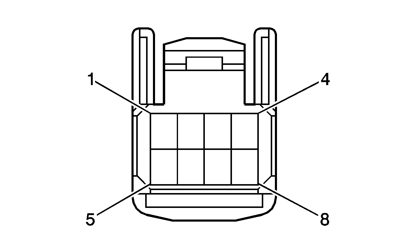
Electronic Brake Control Module (EBCM)
Connector Part Information
|
Pin | Wire | Circuit | Function |
|---|---|---|---|
1 | 3.0 WH/BK | -- | Ground |
2 | 0.5 D-BU/WH | -- | Stop Lamp Switch Signal (Battery) |
3 | -- | -- | Not Used |
4 | 0.3 WH | -- | Left Rear Wheel Speed Sensor Signal |
5 | 0.3 BK | -- | Left Rear Wheel Speed Sensor Control |
6 | 0.3 L-GN | -- | Right Front Wheel Speed Sensor Signal |
7 | 0.3 BN | -- | Right Front Wheel Speed Sensor Control |
8-10 | -- | -- | Not Used |
11 | 0.3 VT | -- | Vehicle Speed Sensor Signal |
12 | 2.0 WH | -- | Battery Positive Voltage |
13 | 3.0 WH/BK | -- | Ground |
14 | 0.3 WH | -- | High Speed GMLAN Serial Data Bus- |
15 | -- | -- | Not Used |
16 | 0.3 D-GN | -- | Right Rear Wheel Speed Sensor Signal |
17 | 0.3 RD | -- | Right Rear Wheel Speed Sensor Control |
18 | 0.3 VT | -- | Left Front Wheel Speed Sensor Signal |
19 | 0.3 L-GN | -- | Left Front Wheel Speed Sensor Control |
20-23 | -- | -- | Not Used |
24 | 3.0 D-BU | -- | Battery Positive Voltage |
25 | 0.3 RD | -- | High Speed GMLAN Serial Data Bus+ |
26-29 | -- | -- | Not Used |
30 | 0.3 PK | -- | Vehicle Stability Control Switch Input |
31-32 | -- | -- | Not Used |
33 | 0.3 RD/BK | -- | Sensor Check Input |
34 | 0.3 D-BU/BK | -- | Ignition Voltage |
Electric Power Steering (EPS) Module X1
Connector Part Information
|
Pin | Wire | Circuit | Function |
|---|---|---|---|
1 | 8.0 D-BU | -- | Battery Positive Voltage |
2 | 8.0 WH/BK | -- | Ground |
Electric Power Steering (EPS) Module X2
Connector Part Information
|
Pin | Wire | Circuit | Function |
|---|---|---|---|
1 | 0.35 L-BU | -- | High Speed GMLAN Serial Data Bus+ |
2-5 | -- | -- | Not Used |
6 | 0.35 D-BU | -- | Ignition Voltage |
7 | 0.35 WH | -- | High Speed GMLAN Serial Data Bus- |
8-12 | -- | -- | Not Used |
Electric Power Steering (EPS) Module X3
Connector Part Information
|
Pin | Wire | Circuit | Function |
|---|---|---|---|
1 | -- | -- | Motor Resolver SIN |
2 | -- | -- | Motor Resolver COS |
3 | -- | -- | Not Used |
4 | -- | -- | Low Reference |
5 | -- | -- | Not Used |
6 | -- | -- | 5-Volt Reference |
Electric Power Steering (EPS) Module X4
Connector Part Information
|
Pin | Wire | Circuit | Function |
|---|---|---|---|
1 | WH | -- | Power Steering Motor Phase W |
2 | BK | -- | Power Steering Motor Phase U |
3 | RD | -- | Power Steering Motor Phase V |
Engine Coolant Temperature (ECT) Sensor
Connector Part Information
|
Pin | Wire | Circuit | Function |
|---|---|---|---|
1 | 0.5 BN | -- | Engine Coolant Temperature (ECT) Sensor Signal |
2 | 0.5 BK | -- | Low Reference |
Engine Cooling Fan - Right
Connector Part Information
|
Pin | Wire | Circuit | Function |
|---|---|---|---|
1 | 3.0 BK | -- | Auxiliary Cooling Fan Motor Supply Voltage |
2 | 3.0 RD | -- | Cooling Fan Motor Supply Voltage |
Engine Cooling Fan - Left
Connector Part Information
|
Pin | Wire | Circuit | Function |
|---|---|---|---|
1 | 3.0 WH/BK | -- | Ground |
2 | 3.0 BK | -- | Cooling Fan Motor Supply Voltage |
Engine Oil Pressure (EOP) Switch
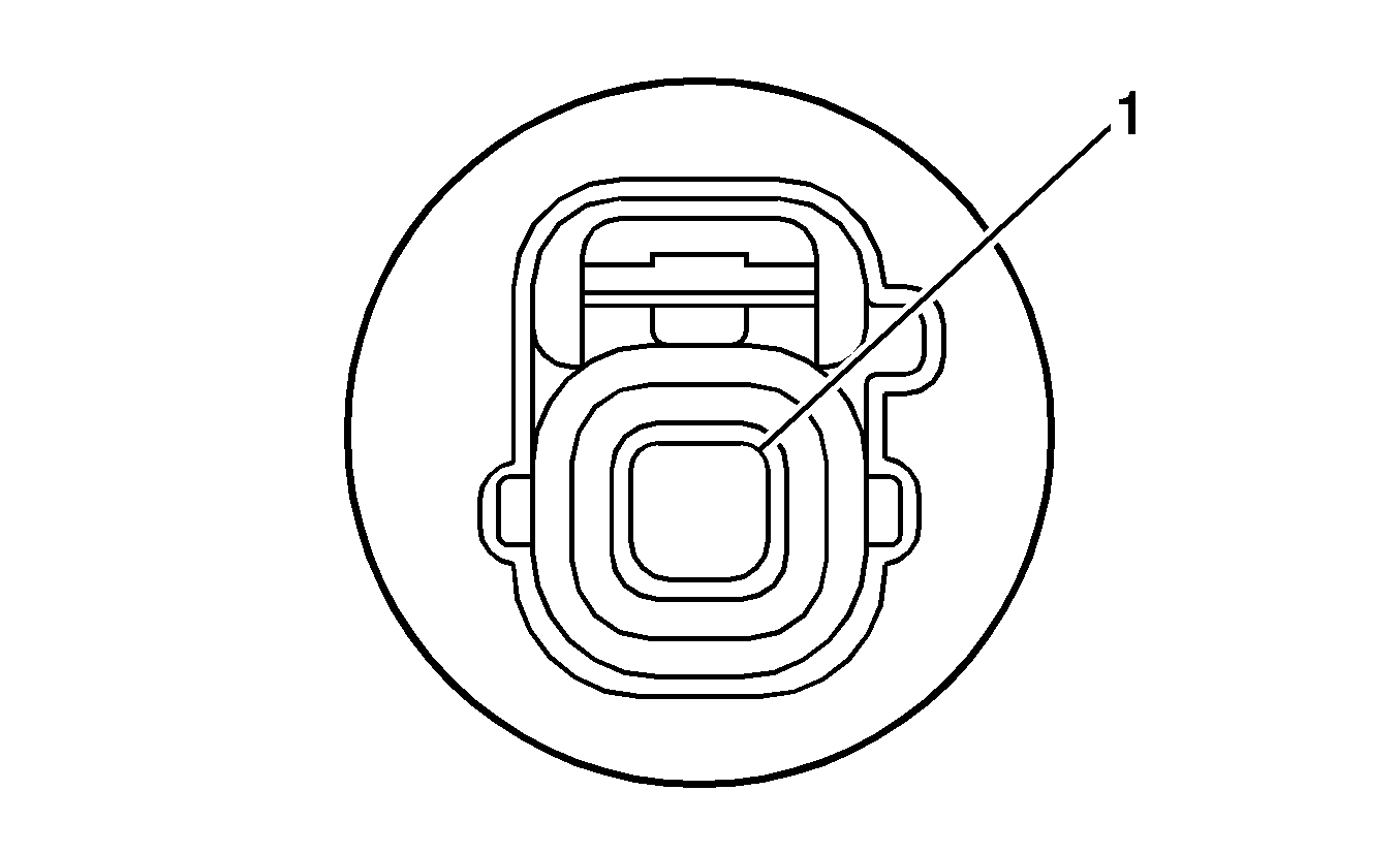
Connector Part Information
|
Pin | Wire | Circuit | Function |
|---|---|---|---|
1 | 0.5 YE/BK | -- | Oil Pressure Switch Signal |
Evaporative Emissions (EVAP) Canister Purge Solenoid Valve
Connector Part Information
|
Pin | Wire | Circuit | Function |
|---|---|---|---|
1 | 0.5 D-BU/BK | -- | EVAP Canister Purge Solenoid Control |
2 | 0.5 BK | -- | Ignition Voltage |
Evaporator Temperature Sensor
Connector Part Information
|
Pin | Wire | Circuit | Function |
|---|---|---|---|
1 | 0.35 L-GN | -- | Low Reference |
2 | 0.35 L-BU | -- | Evaporator Temperature Sensor Signal |
Evaporative Emission (EVAP) Canister Vent Solenoid Valve
Connector Part Information
|
Pin | Wire | Circuit | Function |
|---|---|---|---|
1 | 0.35 D-BU | -- | EVAP Pump Control |
2 | 0.35 BN | -- | Low Reference |
3 | 0.35 VT | -- | EVAP Canister Pressure Sensor Signal |
4 | 0.35 YE | -- | 5-Volt Reference |
5 | -- | -- | Not Used |
6 | 0.35 WH/BK | -- | Ground |
7 | -- | -- | Not Used |
8 | 0.35 WH | -- | EVAP Vent Solenoid Control |
9 | 0.35 BK | -- | Ignition Voltage |
10 | -- | -- | Not Used |
Fan Control Module
Connector Part Information
|
Pin | Wire | Circuit | Function |
|---|---|---|---|
1 | 3.0 BK | -- | Battery positive Voltage |
2 | 0.3 RD/D-GN | -- | Cooling Fan Relay Control |
3 | 3.0 WH/BK | -- | Ground |
Fog Lamp - Left Front
Connector Part Information
|
Pin | Wire | Circuit | Function |
|---|---|---|---|
1 | 0.85 WH/BK | -- | Ground |
2 | 0.85 D-GN | -- | Front Fog Lamp Control |
Fog Lamp - Right Front
Connector Part Information
|
Pin | Wire | Circuit | Function |
|---|---|---|---|
1 | 0.85 WH/BK | -- | Ground |
2 | 0.85 D-GN | -- | Front Fog Lamp Control |
Fuel Injector 1 (LAY)
Connector Part Information
|
Pin | Wire | Circuit | Function |
|---|---|---|---|
1 | 0.85 RD | -- | Ignition Voltage |
2 | 0.5 VT | -- | Fuel Injector 1 Control |
Fuel Injector 1 (LAX)
Connector Part Information
|
Pin | Wire | Circuit | Function |
|---|---|---|---|
1 | 0.75 RD | -- | Ignition Voltage |
2 | 0.5 VT | -- | Fuel Injector 1 Control |
Fuel Injector 2 (LAY)
Connector Part Information
|
Pin | Wire | Circuit | Function |
|---|---|---|---|
1 | 0.85 RD | -- | Ignition Voltage |
2 | 0.5 YE | -- | Fuel Injector 2 Control |
Fuel Injector 2 (LAX)
Connector Part Information
|
Pin | Wire | Circuit | Function |
|---|---|---|---|
1 | 0.75 RD | -- | Ignition Voltage |
2 | 0.5 RD | -- | Fuel Injector 2 Control |
Fuel Injector 3 (LAY)
Connector Part Information
|
Pin | Wire | Circuit | Function |
|---|---|---|---|
1 | 0.85 RD | -- | Ignition Voltage |
2 | 0.5 D-GN | -- | Fuel Injector 3 Control |
Fuel Injector 3 (LAX)
Connector Part Information
|
Pin | Wire | Circuit | Function |
|---|---|---|---|
1 | 0.75 RD | -- | Ignition Voltage |
2 | 0.5 D-GN | -- | Fuel Injector 3 Control |
Fuel Injector 4 (LAY)
Connector Part Information
|
Pin | Wire | Circuit | Function |
|---|---|---|---|
1 | 0.85 RD | -- | Ignition Voltage |
2 | 0.5 L-GN | -- | Fuel Injector 4 Control |
Fuel Injector 4 (LAX)
Connector Part Information
|
Pin | Wire | Circuit | Function |
|---|---|---|---|
1 | 0.75 RD | -- | Ignition Voltage |
2 | 0.5 L-GN | -- | Fuel Injector 4 Control |
Fuel Pump and Sender Assembly
Connector Part Information
|
Pin | Wire | Circuit | Function |
|---|---|---|---|
1 | -- | -- | Not Used |
2 | 0.35 PK | -- | Fuel Level Sensor Signal |
3 | 0.35 BN | -- | Low Reference (FWD) |
0.35 D-BU | -- | Fuel Level Sensor Signal (AWD) | |
4 | 1.0 BK | -- | Ignition Voltage |
5 | 1.0 WH/BK | -- | Ground |
Fuel Pump and Sender Assembly - Secondary (F46)
Connector Part Information
|
Pin | Wire | Circuit | Function |
|---|---|---|---|
1 | 0.35 D-BU | -- | Fuel Level Sensor Signal |
2 | 0.35 BN | -- | Low Reference |
Generator
Connector Part Information
|
Pin | Wire | Circuit | Function |
|---|---|---|---|
1 | 0.5 WH | -- | Battery Positive Voltage |
2 | 0.5 D-GN | -- | Ignition Voltage |
3 | 0.5 D-BU | -- | Generator Field Duty Cycle Signal Out |
4 | 0.5 YE | -- | Charge Indicator Control |
Hazard Warning Switch
Connector Part Information
|
Pin | Wire | Circuit | Function |
|---|---|---|---|
1 | 0.35 WH/BK | -- | Ground |
2 | 0.35 WH | -- | Instrument Panel Dimming Low Control |
3 | 0.35 D-GN | -- | Instrument Panel Dimming Voltage |
4 | 0.35 BG | -- | Hazard Switch Signal |
Headlamp - Left High Beam
Connector Part Information
|
Pin | Wire | Circuit | Function |
|---|---|---|---|
1 | 2.0 RD/BK | -- | Left Headlamp High Beam Control |
2 | 2.0 RD | -- | Left Headlamp High Beam/DRL Low Control |
Headlamp - Left Low Beam
Connector Part Information
|
Pin | Wire | Circuit | Function |
|---|---|---|---|
1 | 0.85 RD | -- | Left Headlamp Low Beam Control |
2 | 0.85 WH/BK | -- | Ground |
Headlamp - Right High Beam
Connector Part Information
|
Pin | Wire | Circuit | Function |
|---|---|---|---|
1 | 2.0 RD/BK | -- | Right Headlamp High Beam Control |
2 | 2.0 RD | -- | Right Headlamp High Beam/DRL Low Control |
Headlamp - Right Low Beam
Connector Part Information
|
Pin | Wire | Circuit | Function |
|---|---|---|---|
1 | 1.25 RD | -- | Right Headlamp Low Beam Control |
2 | 1.25 WH/BK | -- | Ground |
Heated Oxygen Sensor (HO2S) Bank 1 Sensor 2 (LAX without F46))
Connector Part Information
|
Pin | Wire | Circuit | Function |
|---|---|---|---|
1 | 0.5 PK | -- | HO2S Heater Low Control (B1S2) |
2 | 0.5 BK | -- | Ignition Voltage |
3 | 0.5 BK | -- | HO2S High Signal (B1S2) |
4 | 0.5 L-GN/BK | -- | HO2S Low Signal (B1S2) |
Heated Oxygen Sensor (HO2S) Bank 1 Sensor 1 (LAX)
Connector Part Information
|
Pin | Wire | Circuit | Function |
|---|---|---|---|
1 | 1.25 RD | -- | HO2S Heater Low Control (B1S1) |
2 | 1.25 BK | -- | Ignition Voltage |
3 | 0.5 YE | -- | HO2S High Signal (B1S1) |
4 | 0.5 D-BU | -- | HO2S Low Signal (B1S1) |
Heated Oxygen Sensor (HO2S) Bank 1 Sensor 1 (LAY)
Connector Part Information
|
Pin | Wire | Circuit | Function |
|---|---|---|---|
1 | 0.5 RD | -- | HO2S Heater Low Control (B1S1) |
2 | 0.75 BK | -- | Ignition Voltage |
3 | 0.5 YE | -- | HO2S High Signal (B1S1) |
4 | 0.5 D-BU | -- | HO2S Low Signal (B1S1) |
Heated Oxygen Sensor (HO2S) Bank 1 Sensor 2 (LAX with F46)
Connector Part Information
|
Pin | Wire | Circuit | Function |
|---|---|---|---|
1 | 0.5 RD | -- | HO2S Heater Low Control (B1S2) |
2 | 0.5 BK | -- | Ignition Voltage |
3 | 0.5 YE | -- | HO2S High Signal (B1S2) |
4 | 0.5 BN | -- | HO2S Low Signal (B1S2) |
Horn
Connector Part Information
|
Pin | Wire | Circuit | Function |
|---|---|---|---|
1 | 0.5 BK | -- | Horn Control |
Horn Switch
Connector Part Information
|
Pin | Wire | Circuit | Function |
|---|---|---|---|
1 | YE | -- | Horn Relay Control |
2 | BN | -- | Ground |
3 | YE | -- | Horn Relay Control |
4 | BN | -- | Ground |
HVAC Control Module X1
Connector Part Information
|
Pin | Wire | Circuit | Function |
|---|---|---|---|
1 | 0.35 BK | -- | 5-Volt Reference |
2 | 0.35 VT | -- | High Speed GMLAN Serial Data Bus+ |
3 | 0.35 WH | -- | High Speed GMLAN Serial Data Bus- |
4 | 0.35 D-GN | -- | Low Reference |
5 | -- | -- | Not Used |
6 | 0.35 D-BU | -- | A/C Refrigerant Pressure Sensor Signal |
7 | 0.35 VT | -- | A/C Compressor Clutch Control |
8 | 0.35 RD | -- | Ignition Voltage |
9 | 0.35 GY | -- | Heater Relay Control |
10 | 0.35 L-GN | -- | Low Reference |
11 | 0.35 L-BU | -- | Evaporator Temperature Sensor Signal |
12 | 0.35 WH/BK | -- | Ground |
13 | -- | -- | Not Used |
14 | -- | -- | Not Used |
15 | 0.35 YE | -- | A/C Request Signal |
16 | 0.35 BG | -- | Dimming Signal |
HVAC Control Module X2
Connector Part Information
|
Pin | Wire | Circuit | Function |
|---|---|---|---|
1 | 0.35 BN | -- | Battery Positive Voltage |
2-8 | -- | -- | Not Used |
9 | 0.35 PK | -- | Heater Sub #1 Relay Control |
10 | 0.35 BK | -- | Heater Sub #3 Relay Control |
11-13 | -- | -- | Not Used |
14 | 0.35 GY | -- | Heater Request Signal |
15-22 | -- | -- | Not Used |
23 | 0.35 VT | -- | Headlamp Relay Control |
24 | 0.35 D-BU | -- | Generator Turn On Signal |
HVAC Heater Element X1
Connector Part Information
|
Pin | Wire | Circuit | Function |
|---|---|---|---|
1 | 2.0 WH | -- | HTR Sub #1 Relay Power Feed |
2 | -- | -- | Not Used |
3 | 2.0 WH/D-BU | -- | HTR Sub #3 Relay Power Feed |
HVAC Heater Element X2
Connector Part Information
|
Pin | Wire | Circuit | Function |
|---|---|---|---|
1 | 2.0 WH/BK | -- | Ground |
2 | 2.0 WH/BK | -- | Ground |
HVAC Mode Switch
Connector Part Information
|
Pin | Wire | Circuit | Function |
|---|---|---|---|
1 | 0.35 YE | -- | Mode Switch Signal |
2 | 0.35 RD | -- | A/C Mode Indicator |
3 | 0.35 BK | -- | Air Mix Servo - Panel Vents |
4 | 0.35 WH/BK | -- | Ground |
5 | 0.35 PK | -- | Air Mix Servo - Recirculation Indicator |
6 | 0.35 WH | -- | Illumination (+) |
7 | 0.35 D-GN | -- | Illumination (-) |
8 | 0.35 RD | -- | Ignition 1 Voltage |
HVAC Temperature Switch
Connector Part Information
|
Pin | Wire | Circuit | Function |
|---|---|---|---|
1 | -- | -- | Not Used |
2 | 0.35 RD | -- | Ignition 1 Voltage |
3 | 0.35 YE | -- | A/C Switch - Signal |
4 | 0.35 BG | -- | A/C Switch Indicator - Low Reference |
5 | 0.35 D-GN | -- | Instrument Panel Lamps Dimmer Low Control |
6 | 0.35 WH | -- | Instrument Panel lamp Dimmer Switch - Output |
7 | 0.35 RD | -- | Ignition 1 Voltage |
8 | 0.35 GY | -- | Max Hot Switch - Signal |
Ignition Coil 1
Connector Part Information
|
Pin | Wire | Circuit | Function |
|---|---|---|---|
1 | 0.85 RD | -- | Ignition Voltage |
2 | 0.5 YE | -- | Low Reference |
3 | 0.5 WH/D-BU | -- | IC 1 Control |
4 | 0.5 WH/BK | -- | Ground |
Ignition Coil 2
Connector Part Information
|
Pin | Wire | Circuit | Function |
|---|---|---|---|
1 | 0.85 RD | -- | Ignition Voltage |
2 | 0.5 YE | -- | Low Reference |
3 | 0.5 BK | -- | IC 2 Control |
4 | 0.5 WH/BK | -- | Ground |
Ignition Coil 3
Connector Part Information
|
Pin | Wire | Circuit | Function |
|---|---|---|---|
1 | 0.85 RD | -- | Ignition Voltage |
2 | 0.5 YE | -- | Low Reference |
3 | 0.5 D-BU/BK | -- | IC 3 Control |
4 | 0.5 WH/BK | -- | Ground |
Ignition Coil 4
Connector Part Information
|
Pin | Wire | Circuit | Function |
|---|---|---|---|
1 | 0.85 RD | -- | Ignition Voltage |
2 | 0.5 YE | -- | Low Reference |
3 | 0.5 BK | -- | IC 4 Control |
4 | 0.5 WH/BK | -- | Ground |
Ignition Key Alarm Switch
Connector Part Information
|
Pin | Wire | Circuit | Function |
|---|---|---|---|
1 | 0.35 D-BU | -- | Ignition Key Alarm Switch Signal |
2 | 0.35 WH/BK | -- | Ground |
Ignition Lock Cylinder Control Solenoid
Connector Part Information
|
Pin | Wire | Circuit | Function |
|---|---|---|---|
1 | 0.35 WH/BK | -- | Ground |
2 | 0.35 YE | -- | -- |
Ignition Switch
Connector Part Information
|
Pin | Wire | Circuit | Function |
|---|---|---|---|
1 | 0.35 WH | -- | Ignition Voltage |
2 | 0.35 RD | -- | Ignition Relay Feed |
3 | 0.35 GY | -- | Ignition Accessory Feed (LAY) |
0.5 GY | -- | Ignition Accessory Feed (LAX) | |
4 | 0.35 D-GN | -- | Ignition Run |
5 | -- | -- | Not Used |
6 | 0.35 BN | -- | Ignition Accessory Feed (LAY) |
2 BN | -- | Ignition Accessory Feed (LAX) | |
7 | 0.35 D-BU | -- | Battery Positive Voltage (LAY) |
3 D-BU | -- | Battery Positive Voltage (LAX) | |
8 | 0.35 BK | -- | Ignition Voltage (LAY) |
0.35 BK | -- | Ignition Voltage (LAY) | |
8 | 3 BK | -- | Ignition Voltage(LAX) |
Inflatable Restraint Front End Sensor - Left
Connector Part Information
|
Pin | Wire | Circuit | Function |
|---|---|---|---|
1 | 0.5 BK | -- | Discriminating Sensor - Low Reference |
2 | 0.5 WH | -- | Discriminating Sensor - Signal |
Inflatable Restraint Front End Sensor - Right
Connector Part Information
|
Pin | Wire | Circuit | Function |
|---|---|---|---|
1 | 0.5 BK | -- | Discriminating Sensor - Low Reference |
2 | 0.5 WH | -- | Discriminating Sensor - Signal |
Inflatable Restraint Front Passenger Presence System (PPS) Module
Connector Part Information
|
Pin | Wire | Circuit | Function |
|---|---|---|---|
1-2 | -- | -- | Not Used |
3 | OG | -- | Seat Position Sensor - Low Reference |
4 | VT | -- | Seat Position Sensor - Right - Signal |
5 | WH/BK | -- | Ground |
6 | WH | -- | PPS - Signal |
7 | L-GN | -- | PPS - Voltage |
8 | YE | -- | Seat Belt Tension Sensor - Passenger - Ground |
9 | BK | -- | Battery Positive Voltage |
10 | WH | -- | Low Speed Serial Data |
11 | WH | -- | Occupant Sensor - Serial Data + |
12 | BK | -- | Occupant Sensor - Serial Data - |
13 | D-GN | -- | Seat Belt Switch - Right - Signal |
14 | PK | -- | Seat Belt Switch - Right - Low Reference |
15 | GY | -- | PPS - Ground |
16 | RD | -- | Seat Belt Tension Sensor - Passenger - Signal |
17 | D-GN | -- | Seat Belt Tension Sensor - Passenger - Voltage |
18 | -- | -- | Not Used |
Inflatable Restraint Front Passenger Presence System (PPS) Sensor
Connector Part Information
|
Pin | Wire | Circuit | Function |
|---|---|---|---|
1 | GY | -- | PPS - Ground |
2 | WH | -- | PPS - Signal |
3 | L-GN | -- | PPS - Voltage |
Inflatable Restraint I/P Module X1
Connector Part Information
|
Pin | Wire | Circuit | Function |
|---|---|---|---|
1 | YE/D-GN | -- | I/P Module - Stage 2 - High Control |
2 | YE/RD | -- | I/P Module - Stage 2 - Low Control |
Inflatable Restraint I/P Module X2
Connector Part Information
|
Pin | Wire | Circuit | Function |
|---|---|---|---|
1 | YE | -- | I/P Module - Stage 1 - Low Control |
2 | YE/BK | -- | I/P Module - Stage 1 - High Control |
Inflatable Restraint Roof Rail Module - Left
Connector Part Information
|
Pin | Wire | Circuit | Function |
|---|---|---|---|
1 | 0.5 YE | -- | Side Impact Module - Left Front - High Control |
2 | 0.5 YE/BK | -- | Side Impact Module - Left Front - Low Control |
Inflatable Restraint Roof Rail Module - Right
Connector Part Information
|
Pin | Wire | Circuit | Function |
|---|---|---|---|
1 | 0.5 YE | -- | Side Impact Module - Right Front - High Control |
2 | 0.5 YE/BK | -- | Side Impact Module - Right Front - Low Control |
Inflatable Restraint Seat Belt Tension Sensor -- Passenger
Connector Part Information
|
Pin | Wire | Circuit | Function |
|---|---|---|---|
1 | 0.35 YE | -- | Low Reference |
2 | 0.35 D-GN | -- | Passenger Seat Belt Tension Sensor Voltage Reference |
3 | 0.35 RD | -- | Passenger Seat Belt Tension Sensor Voltage Signal |
Inflatable Restraint Seat Position Sensor - Passenger
Connector Part Information
|
Pin | Wire | Circuit | Function |
|---|---|---|---|
1 | OG | -- | Low Reference |
2 | VT | -- | Seat Position Sensor Right - Signal |
Inflatable Restraint Side Impact Module - Left
Connector Part Information
|
Pin | Wire | Circuit | Function |
|---|---|---|---|
1 | 0.5 YE/BK | -- | Side Impact Module - Left - High Control |
2 | 0.5 YE | -- | Side Impact Module - Left - Low Control |
Inflatable Restraint Side Impact Module - Right
Connector Part Information
|
Pin | Wire | Circuit | Function |
|---|---|---|---|
1 | 0.5 YE/BK | -- | Side Impact Module - Right - High Control |
2 | 0.5 YE | -- | Side Impact Module - Right - Low Control |
Inflatable Restraint Side Impact Sensor (SIS) - Left
Connector Part Information
|
Pin | Wire | Circuit | Function |
|---|---|---|---|
1 | 0.5 WH | -- | Side Impact Module - Left Rear - High Control |
2 | 0.5 BK | -- | Side Impact Module - Left Rear - Low Control |
3 | 0.5 RD | -- | Side Impact Module - Left Rear - Low Control |
4 | 0.5 D-GN | -- | Side Impact Module - Left Rear - High Control |
Inflatable Restraint Side Impact Sensor (SIS) - Left Rear
Connector Part Information
|
Pin | Wire | Circuit | Function |
|---|---|---|---|
1-2 | -- | -- | Not Used |
3 | 0.5 BK | -- | Inflatable Restraint Side Impact Sensor - Left Rear - Low Control |
4 | 0.5 WH | -- | Inflatable Restraint Side Impact Sensor - Left Rear - High Control |
Inflatable Restraint Side Impact Sensor (SIS) - Right
Connector Part Information
|
Pin | Wire | Circuit | Function |
|---|---|---|---|
1 | 0.5 WH | -- | Inflatable Restraint Side Impact Sensor - Right Rear - High Control |
2 | 0.5 BK | -- | Inflatable Restraint Side Impact Sensor - Right Rear - Low Control |
3 | 0.5 RD | -- | Inflatable Restraint Side Impact Sensor - Right Rear - Low Control |
4 | 0.5 D-GN | -- | Inflatable Restraint Side Impact Sensor - Right Rear - High Control |
Inflatable Restraint Side Impact Sensor (SIS) - Right Rear
Connector Part Information
|
Pin | Wire | Circuit | Function |
|---|---|---|---|
1-2 | -- | -- | Not Used |
3 | 0.5 BK | -- | Inflatable Restraint Side Impact Sensor - Right Rear - Low Control |
4 | 0.5 WH | -- | Inflatable Restraint Side Impact Sensor - Right Rear - High Control |
Inflatable Restraint Sensing and Diagnostic Module (SDM) X1
Connector Part Information
|
Pin | Wire | Circuit | Function |
|---|---|---|---|
1 | 0.5 YE/RD | -- | I/P Module - Stage 1 - High Control |
2 | 0.5 YE/D-GN | -- | I/P Module - Stage 1 - Low Control |
3 | 0.5 YE | -- | I/P Module - Stage 2 - High Control |
4 | 0.5 YE/BK | -- | I/P Module - Stage 2 - Low Control |
5 | 0.5 YE/BK | -- | Steering Wheel Module - Stage 1 - High Control |
6 | 0.5 YE | -- | Steering Wheel Module - Stage1 - Low Control |
7 | 0.5 YE/D-GN | -- | Steering Wheel Module - Stage2 - Low Control |
8 | 0.5 YE/RD | -- | Steering Wheel Module - Stage2 - High Control |
9-12 | -- | -- | Not Used |
13 | 0.35 YE | -- | High Speed GMLAN Serial Data Bus+ |
14-15 | -- | -- | Not Used |
16 | 0.35 WH | -- | Low Speed Serial Data |
17 | 0.35 BK | -- | SIR Defeat Indicator Lamp - Passenger - Output |
18-20 | -- | -- | Not Used |
21 | 0.5 BK | -- | Ignition 1 Voltage |
22 | 0.35 WH | -- | High Speed GMLAN Serial Data Bus- |
23 | 0.35 RD | -- | SRS ON Indicator Lamp - Passenger Output |
24 | 0.5 L-BU | -- | Onstar |
25 | 0.5 WH/BK | -- | Ground |
26 | 0.5WH/BK | -- | Ground |
27 | 0.5 BK | -- | Discriminating Sensor - Low Reference |
28 | 0.5 BK | -- | Discriminating Sensor - Low Reference |
29 | 0.5 WH | -- | Discriminating Sensor - Signal |
30 | 0.5 WH | -- | Discriminating Sensor - Signal |
Inflatable Restraint Sensing and Diagnostic Module (SDM) X2
Connector Part Information
|
Pin | Wire | Circuit | Function |
|---|---|---|---|
1 | 0.5 YE | -- | Seat Belt Pretensioner - Driver - Low Control |
2 | 0.5 YE/BK | -- | Seat Belt Pretensioner - Driver - High Control |
3-5 | -- | -- | Not Used |
6 | 0.5 YE/BK | -- | Side Impact Module - LF - Low Control |
7 | 0.5 YE | -- | Side Impact Module - LF - High Control |
8 | 0.5 D-GN | -- | Inflatable Restraint Side Impact Sensor - Left Rear - High Control |
9 | 0.5 YE/BK | -- | Inflatable Restraint Side Impact Module - Left - High Control |
10 | 0.5 YE | -- | Inflatable Restraint Side Impact Module - Left - Low Control |
11 | 0.5 D-GN | -- | Seat Belt Switch - Left - Signal |
12 | 0.5 YE | -- | Seat Belt Switch - Left - Low Reference |
13 | 0.5 BK | -- | Seat Position Sensor - Low Reference |
14 | 0.5 WH | -- | Seat Position Sensor - Left - Signal |
15 | 0.5 RD | -- | Inflatable Restraint Side Impact Sensor - Left Rear - Low Control |
Inflatable Restraint Sensing and Diagnostic Module (SDM) X3
Connector Part Information
|
Pin | Wire | Circuit | Function |
|---|---|---|---|
1-3 | -- | -- | Not Used |
4 | 0.5 YE/BK | -- | Seat Belt Pretensioner - Passenger - High Control |
5 | 0.5 YE | -- | Seat Belt Pretensioner - Passenger - Low Control |
6 | 0.5 YE | -- | Side Impact Module - Right - Low Control |
7 | 0.5 YE/BK | -- | Side Impact Module - Right - High Control |
8 | 0.5 D-GN | -- | Side Impact Module - Right Rear - High Control |
9 | 0.5 YE | -- | Side Impact Module - LF - High Control |
10 | 0.5 YE/BK | -- | Side Impact Module - LF - Low Control |
11 | 0.5 RD | -- | Side Impact Module - Right Rear - Low Control |
12 | 0.35 WH | -- | Occupant Sensor - Serial Data (+) |
13 | 0.35 BK | -- | Occupant Sensor - Serial Data (-) |
14- 15 | -- | -- | Not Used |
Inflatable Restraint Steering Wheel Module X1
Connector Part Information
|
Pin | Wire | Circuit | Function |
|---|---|---|---|
1 | D-BU | -- | Steering Wheel Module - Stage1 - High Control |
2 | YE | -- | Steering Wheel Module - Stage1 - Low Control |
Inflatable Restraint Steering Wheel Module X2
Connector Part Information
|
Pin | Wire | Circuit | Function |
|---|---|---|---|
1 | BK | -- | Steering Wheel Module - Stage2 - High Control |
2 | RD | -- | Steering Wheel Module - Stage2 - Low Control |
Inflatable Restraint Steering Wheel Module Coil X1
Connector Part Information
|
Pin | Wire | Circuit | Function |
|---|---|---|---|
1 | 0.35 YE | -- | Steering Wheel Controls - Cruise Control - Signal |
2 | 0.35 BN | -- | Steering Wheel Controls - Cruise Control - Ground |
3 | -- | -- | Not Used |
4 | 0.35 L-BU | -- | Steering Wheel Controls - Radio - Power |
5 | 0.35 PK | -- | Steering Wheel Controls - Radio - Source Signal |
6 | 0.35 BG | -- | Steering Wheel Controls - Radio - Signal |
7 | -- | -- | Not Used |
8 | 0.35 L-GN | -- | Horn Relay Control |
9-11 | -- | -- | Not Used |
12 | 0.35 D-GN | -- | Steering Wheel Controls - Radio - Dimming Signal |
Inflatable Restraint Steering Wheel Module Coil X2
Connector Part Information
|
Pin | Wire | Circuit | Function |
|---|---|---|---|
1 | 0.5 YE/BK | -- | Steering Wheel Module - Stage1 - High Control |
2 | 0.5 YE | -- | Steering Wheel Module - Stage1 - Low Control |
3 | 0.5 YE/D-GN | -- | Steering Wheel Module - Stage2 - Low Control |
4 | 0.5 YE/RD | -- | Steering Wheel Module - Stage2 - High Control |
Inflatable Restraint Steering Wheel Module Coil X3
Connector Part Information
|
Pin | Wire | Circuit | Function |
|---|---|---|---|
1 | 0.5 D-BU | -- | Steering Wheel Module - Stage1 - High Control |
2 | 0.5 YE | -- | Steering Wheel Module - Stage1 - Low Control |
3 | 0.5 RD | -- | Steering Wheel Module - Stage2 - Low Control |
4 | 0.5 BK | -- | Steering Wheel Module - Stage2 - High Control |
Inflatable Restraint Steering Wheel Module Coil X4
Connector Part Information
|
Pin | Wire | Circuit | Function |
|---|---|---|---|
1 | 0.35 D-BU | -- | Ground |
2-4 | -- | -- | Not Used |
5 | 0.35 WH/RD | -- | Instrument Panel Dimming Voltage |
6-7 | -- | -- | Not Used |
8 | 0.35 WH | -- | Steering Wheel Controls - Radio - Power |
9 | 0.35 GY | -- | Steering Wheel Controls - Radio - Source Signal |
10 | 0.35 BN | -- | Steering Wheel Controls - Radio - Signal |
Inflatable Restraint Steering Wheel Module Coil X5
Connector Part Information
|
Pin | Wire | Circuit | Function |
|---|---|---|---|
1-2 | -- | -- | Not Used |
3 | RD | -- | -- |
4 | BK | -- | -- |
Inside Rearview Mirror (ISRVM) (UE1)
Connector Part Information
|
Pin | Wire | Circuit | Function |
|---|---|---|---|
1 | -- | -- | Not Used |
2 | 0.35 D-GN | -- | Microphone (-) |
3-7 | -- | -- | Not Used |
8 | 0.5 BN | -- | Ground |
9 | -- | -- | Not Used |
10 | 0.35 RD | -- | Microphone (+) |
11 | 0.35 L-BU | -- | Key Pad Signal |
12 | 0.35 YE | -- | Accessory Power |
13 | -- | -- | Not Used |
14 | 0.35 BG | -- | Indicator Control |
15 | 0.35 L-GN | -- | Illumination Control |
16 | -- | -- | Not Used |
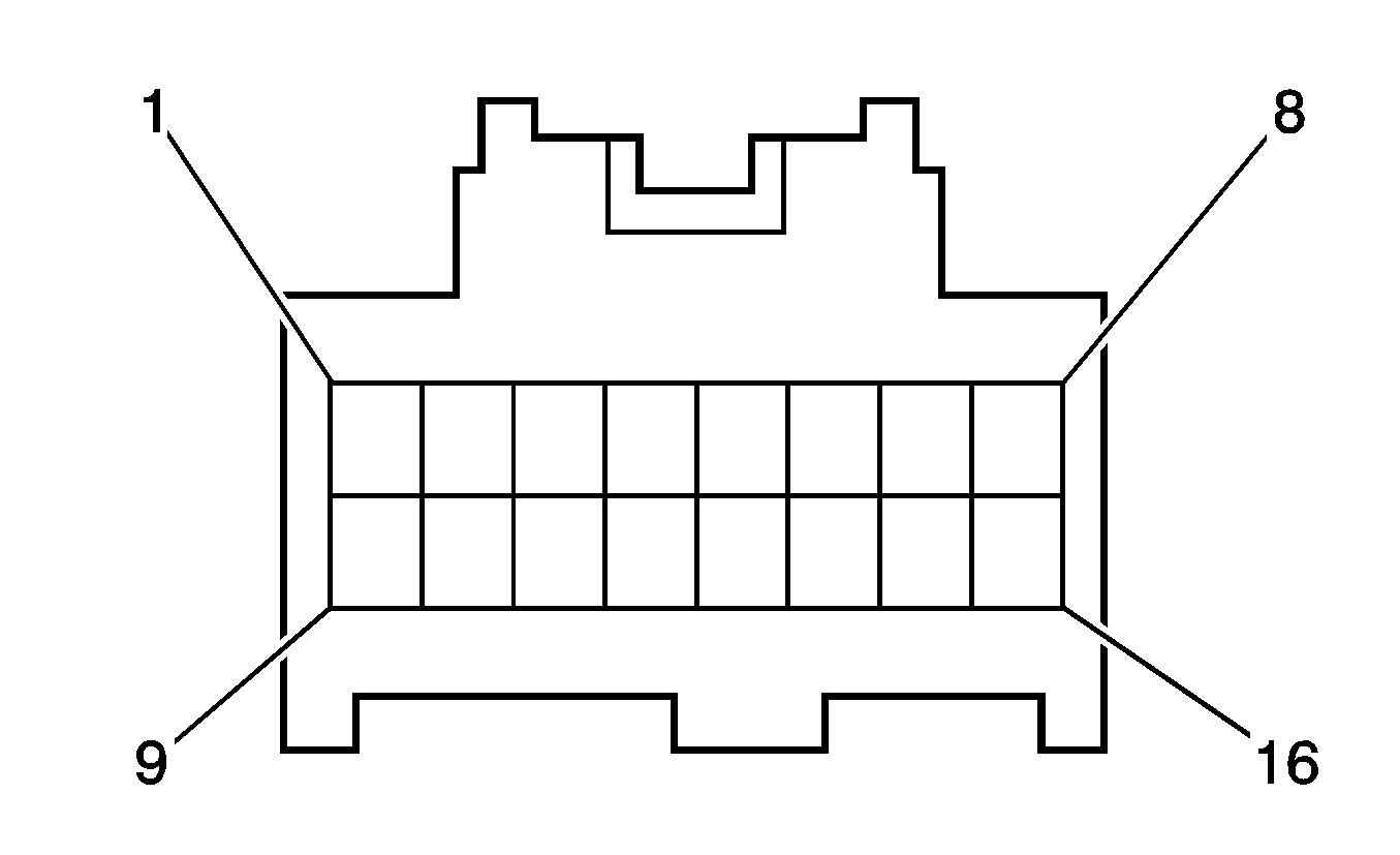
Instrument Panel Cluster (IPC)
Connector Part Information
|
Pin | Wire | Circuit | Function |
|---|---|---|---|
1 | 0.35 WH | -- | SRS Indicator Control |
2 | 0.35 BG | -- | Washer Fluid Level Switch Indicator Control |
3 | 0.35 D-BU | -- | Headlamp Indicator Low Reference |
4 | 0.35 RD | -- | Dimmer Relay Supply Voltage - High Beam |
5 | 0.35 D-BU | -- | Flasher Relay Signal - Right Turn |
6 | 0.35 YE | -- | Flasher Relay Signal - Left Turn |
7 | 0.35 PK | -- | Tire Pressure Monitoring System Signal |
8 | -- | -- | Not Used |
9 | 0.35 L-GN | -- | Low Reference |
10 | 0.35 BN | -- | Fuel Level Signal |
11 | 0.35 WH/BK | -- | Ground |
12-15 | -- | -- | Not Used |
16 | 0.5 PK | -- | Fog Lights Indicator Control |
17 | 0.35 GY | -- | DRL Indicator Control |
18-19 | -- | -- | Not Used |
20 | 0.35 RD | -- | MIL Control |
21-22 | -- | -- | Not Used |
23 | 0.35 GY | -- | Ambient Air Temperature Sensor Signal |
24 | 0.35 D-GN | -- | Tail Lamp Relay Signal Control |
25 | 0.35 PK | -- | Fuel Level Signal (+) |
26 | 0.35 WH | -- | Instrument Panel Lamps Dimmer Switch - Output |
27 | 0.35 D-GN | -- | High Speed GMLAN Serial Data Bus+ |
28 | 0.35 WH | -- | High Speed GMLAN Serial Data Bus- |
29 | 0.35 WH | -- | Instrument Panel Lamps Dimmer Switch - Output |
30 | 0.35 BN | -- | Ground |
31 | -- | -- | Not Used |
32 | 0.35 RD | -- | Battery Positive Voltage |
33 | 0.35 BK | -- | Ignition Voltage |
34 | -- | -- | Not Used |
35 | 0.35 L-GN | -- | Brake Indication Control |
36 | 0.35 VT | -- | Vehicle Speed Sensor Signal |
37 | -- | -- | Not Used |
38 | 0.35 D-GN | -- | Engine Oil Pressure Signal |
39 | 0.35 YE | -- | Generator Turn On Signal |
40 | 0.35 BG | -- | Brake Fluid level Sensor Signal |
Knock Sensor (KS)
Connector Part Information
|
Pin | Wire | Circuit | Function |
|---|---|---|---|
1 | 0.5 WH | -- | Knock Sensor 1 Signal (LAY) |
0.3 WH | -- | Knock Sensor 1 Signal (LAX) | |
2 | 0.5 BK | -- | Knock Sensor 1 Signal (LAY) |
0.3 BK | -- | Knock Sensor 1 Signal (LAX) |
License Lamp
Connector Part Information
|
Pin | Wire | Circuit | Function |
|---|---|---|---|
1 | 0.5 D-GN | -- | Ground |
2 | 0.5 WH/BK | -- | Tail Lamp Relay Supply Voltage |
Liftgate Latch Assembly
Connector Part Information
|
Pin | Wire | Circuit | Function |
|---|---|---|---|
1 | 2.0 GN | -- | Rear Motor Unlatch Control |
2 | 2.0 BG | -- | Rear Motor Latch Control |
3 | 0.35 WH/BK | -- | Ground |
4 | 0.35 L-GN | -- | Liftgate Ajar Switch Signal |
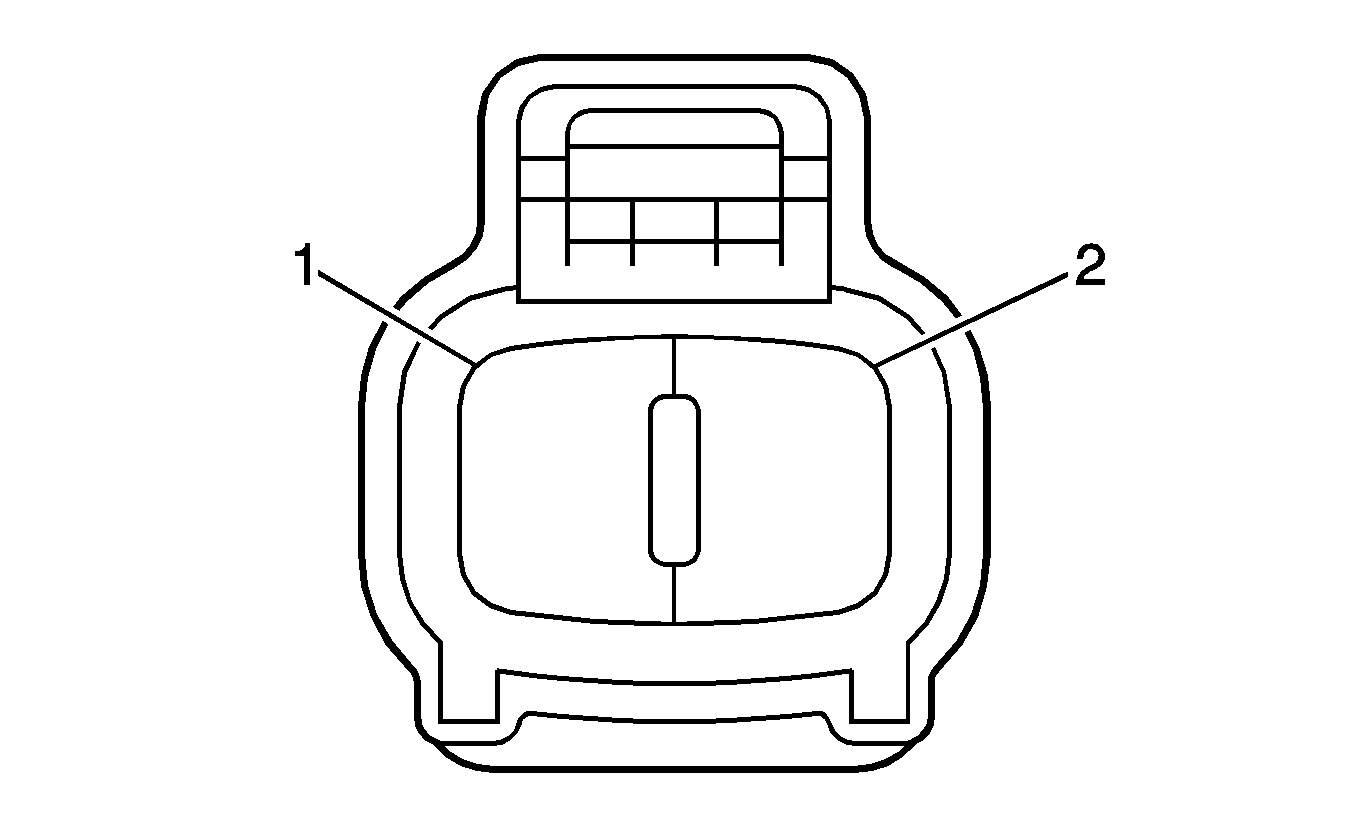
Mass Air Flow (MAF) Sensor
Connector Part Information
|
Pin | Wire | Circuit | Function |
|---|---|---|---|
1 | 0.5 PK | -- | Battery Positive Voltage |
2 | 0.5 BN/WH | -- | Low Reference |
3 | 0.5 BK | -- | IAT Sensor Signal |
4 | 0.5 BK | -- | MAF Sensor Signal |
5 | 0.5 VT | -- | Low Reference |
Outside Rearview Mirror (OSRVM) - Driver
Connector Part Information
|
Pin | Wire | Circuit | Function |
|---|---|---|---|
1-2 | -- | -- | Not Used |
3 | 0.35 BK | -- | Power Window Switch Left/Right Control |
4 | 0.35 YE | -- | Mirror Motor Power |
5 | 0.35 D-BU | -- | Power Window Switch Up/Down Control |
Outside Rearview Mirror (OSRVM) - Passenger
Connector Part Information
|
Pin | Wire | Circuit | Function |
|---|---|---|---|
1-2 | -- | -- | Not Used |
3 | 0.35 L-GN | -- | Power Window Switch Left/Right Control - Passenger |
4 | 0.35 YE | -- | Mirror Motor Power |
5 | 0.35 D-GN | -- | Power Window Switch Up/Down Control - Passenger |
Outside Rearview Mirror (OSRVM) Switch
Connector Part Information
|
Pin | Wire | Circuit | Function |
|---|---|---|---|
1 | -- | -- | Not Used |
2 | 0.35 L-GN | -- | Power Window Switch Left/Right Control - Passenger |
3 | 0.35 D-GN | -- | Power Window Switch Up/Down Control - Passenger |
4 | 0.35 D-BU | -- | Power Window Switch Up/Down Control - Driver |
5 | 0.35 BK | -- | Power Window Switch Left/Right Control - Driver |
6 | 0.35 YE | -- | Mirror Motor Power |
7 | 0.35 WH/BK | -- | Ground |
8 | 0.35 GY | -- | Ignition 1 Voltage |
9-10 | -- | -- | Not Used |
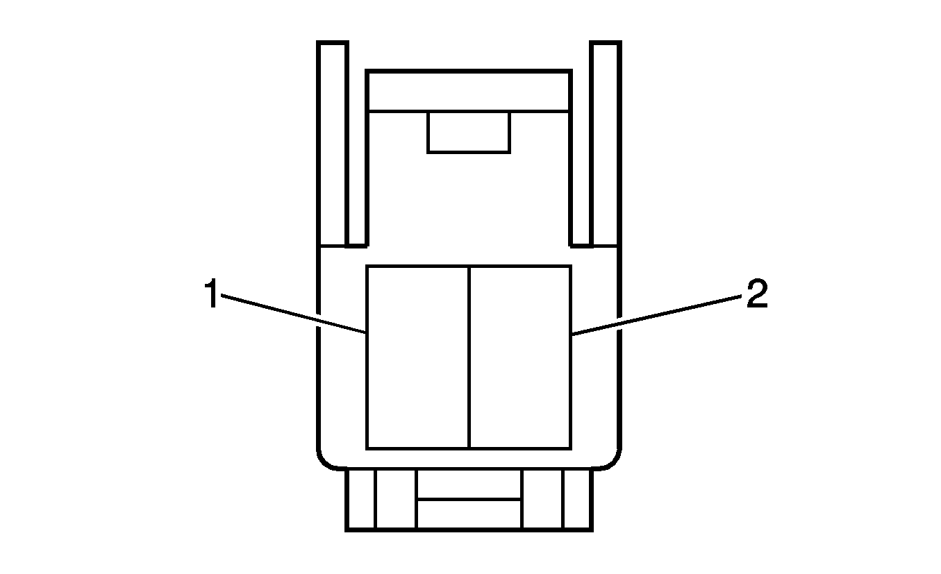
Parking Brake Switch
Connector Part Information
|
Pin | Wire | Circuit | Function |
|---|---|---|---|
1 | 0.5 BG | -- | Park Brake Switch Signal |
Park/Neutral Position (PNP) Switch
Connector Part Information
|
Pin | Wire | Circuit | Function |
|---|---|---|---|
1 | 0.5 RD | -- | Backup Lamp Feed |
2 | 0.5 D-GN | -- | Ignition 1 Voltage |
3 | 0.5 BN | -- | PNP Switch Second Signal (without MVD) |
4 | 0.5 WH | -- | Ignition 1 Voltage |
5 | 0.5 L-GN | -- | Park/Neutral Switch Signal |
6 | 0.5 VT | -- | PNP Switch Park Signal |
7 | 0.5 PK | -- | PNP Switch Driver Signal (without MVD) |
0.5 PK/D-GN | -- | PNP Switch Driver Signal (MVD) | |
8 | 0.5 GY | -- | PNP Switch Low Signal (without MVD) |
-- | -- | PNP Switch Low Signal (MVD) | |
9 | 0.5 BK | -- | PNP Switch Neutral Signal |
Park/Turn Signal Lamp - Left
Connector Part Information
|
Pin | Wire | Circuit | Function |
|---|---|---|---|
1 | 0.5 YE | -- | Flasher Relay Power Feed |
2 | 0.5 D-GN | -- | Turn Lamp Relay Power Feed |
3 | 0.5 WH/BK | -- | Ground |
Park/Turn Signal Lamp - Right
Connector Part Information
|
Pin | Wire | Circuit | Function |
|---|---|---|---|
1 | 0.5 D-BU/RD | -- | Flasher Relay Power Feed |
2 | 0.5 D-GN | -- | Turn Lamp Relay Power Feed |
3 | 0.5 WH/BK | -- | Ground |
Powertrain Control Module (PCM) X1 (LAY)
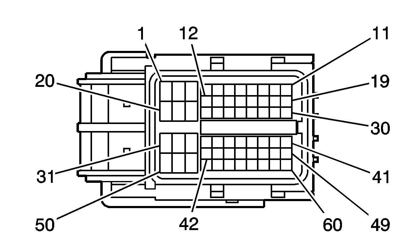
Connector Part Information
|
Pin | Wire | Circuit | Function |
|---|---|---|---|
1 | 1.25 BK | -- | Ignition Voltage |
2 | 1.25 BK | -- | Ignition Voltage |
3 | 0.3 BK | -- | Battery Positive Voltage |
4-6 | -- | -- | Not Used |
7 | 0.3 OG | -- | Fuel Pump Relay Control |
8 | 0.3 VT | -- | Vehicle Speed Sensor Signal |
9 | 0.3 WH/BK | -- | Ground |
10 | 0.3 L-GN/BK | -- | Immobilizer Signal Out |
11 | 0.3 PK | -- | Immobilizer Signal In |
12 | -- | -- | Not Used |
13 | 0.3 D-BU/YE | -- | Accessory Relay Control |
14 | 0.3 WH/D-GN | -- | Ignition Voltage |
15 | 0.3 GY | -- | Engine Speed Signal |
16-19 | -- | -- | Not Used |
20 | 1.25 PK | -- | Battery Positive Voltage |
21-23 | -- | -- | Not Used |
24 | 0.3 RD | -- | MIL Control |
25 | -- | -- | Not Used |
26 | 0.5 OD | -- | Shift Lock Relay Control |
27 | 0.5 PK | -- | Low Speed Serial Data |
28 | 0.3 BK | -- | Ignition Voltage |
29-30 | -- | -- | Not Used |
31 | 0.5 BK | -- | Park Lamp Switch Signal |
32 | 0.3 WH/BK | -- | Ground |
33 | 0.5 D-GN | -- | Rear Defog Supply Voltage |
34 | 0.3 RD | -- | EVAP Pump Control |
35 | 0.3 RD | -- | Stop Lamp Switch Signal (Ignition) |
36 | 0.5 D-BU | -- | Stop Lamp Switch Signal (Battery) |
37-39 | -- | -- | Not Used |
40 | 0.3 D-BU/BK | -- | Cruise Control Switch Signal |
41 | 0.3 YE | -- | High Speed GMLAN Serial Data Bus+ |
42 | 0.3 WH | -- | EVAP Vent Solenoid Control |
43 | 0.3 RD/D-GN | -- | Cooling Fan Relay Control |
44 | 0.3 D-BU | -- | Main Relay Control |
45-47 | -- | -- | Not Used |
48 | 0.5 L-GN | -- | Park/Neutral Switch Signal |
49 | 0.3 WH | -- | High Speed GMLAN Serial Data Bus- |
50-54 | -- | -- | Not Used |
55 | 0.3 D-BU | -- | 5-Volt Reference |
56 | 0.3 YE | -- | 5-Volt Reference |
57 | 0.3 PK | -- | APP Sensor 1 Signal |
58 | 0.3 BK | -- | APP Sensor 2 Signal |
59 | 0.3 RD | -- | Low Reference |
60 | 0.3 OG | -- | Low Reference |
Powertrain Control Module (PCM) X1 (LAX)
Connector Part Information
|
Pin | Wire | Circuit | Function |
|---|---|---|---|
1 | 1.25 BK | -- | Ignition Voltage |
2 | 1.25 BK | -- | Ignition Voltage |
3 | 0.3 BK | -- | Battery Positive Voltage |
4-6 | -- | -- | Not Used |
7 | 0.3 OG | -- | Fuel Pump Relay Control |
8 | 0.3 VT | -- | Vehicle Speed Sensor Signal |
9 | 0.3 WH/BK | -- | Ground |
10 | 0.3 L-GN/BK | -- | Immobilizer Signal Out |
11 | 0.3 PK | -- | Immobilizer Signal In |
12-14 | -- | -- | Not Used |
15 | 0.3 GY | -- | Engine Speed Signal |
16 | 0.3 WH | -- | Shift Switch Tap Up Signal |
17-19 | -- | -- | Not Used |
20 | 1.25 PK | -- | Battery Positive Voltage |
21 | 0.3 RD | -- | Low Speed Cooling Fan Relay Control |
22 | 0.3 WH | -- | High Speed Cooling Fan Relay Control |
23 | -- | -- | Not Used |
24 | 0.3 RD | -- | MIL Control |
25-26 | -- | -- | Not Used |
27 | 0.5 PK | -- | Low Speed Serial Data |
28 | 0.3 BK | -- | Ignition Voltage |
29-30 | -- | -- | Not Used |
31 | 0.5 BK | -- | Rear Defog Supply Voltage |
32 | 0.3 WH/BK | -- | Ground |
33 | 0.5 D-GN | -- | Park Lamp Switch Signal |
34 | 0.3 RD | -- | EVAP Pump Control |
35 | 0.3 RD | -- | Stop Lamp Switch Signal (Ignition) |
36 | 0.5 D-BU | -- | Stop Lamp Switch Signal (Battery) |
37-39 | -- | -- | Not Used |
40 | 0.3 D-BU/BK | -- | Cruise Control Switch Signal |
41 | 0.3 YE | -- | High Speed GMLAN Serial Data Bus+ |
42 | 0.3 WH | -- | EVAP Vent Solenoid Control |
43 | -- | -- | Not Used |
44 | 0.3 D-BU | -- | Main Relay Control |
45-47 | -- | -- | Not Used |
48 | 0.5 L-GN | -- | Park/Neutral Switch Signal |
49 | 0.3 WH | -- | High Speed GMLAN Serial Data Bus- |
50 | -- | -- | Not Used |
51 | 0.3 RD | -- | Shift Switch Tap Down Signal |
52-54 | -- | -- | Not Used |
55 | 0.3 D-BU | -- | 5-Volt Reference |
56 | 0.3 YE | -- | 5-Volt Reference |
57 | 0.3 PK | -- | APP Sensor 1 Signal |
58 | 0.3 BK | -- | APP Sensor 2 Signal |
59 | 0.3 RD | -- | Low Reference |
60 | 0.3 OG | -- | Low Reference |
Powertrain Control Module (PCM) X2 (LAY)

Connector Part Information
|
Pin | Wire | Circuit | Function |
|---|---|---|---|
1-38 | -- | -- | Not Used |
39 | 0.5 VT | -- | Shift Solenoid Valve SLT Low Control |
40 | 0.5 L-GN | -- | Shift Solenoid Valve SLT High Control |
41 | 0.5 D-BU | -- | TAC Motor Control - 2 |
42 | 0.5 PK | -- | TAC Motor Control - 1 |
43 | 1.25 WH/BK | -- | Ground |
44 | 2.0 WH/BK | -- | Ground |
45 | 2.0 WH/BK | -- | Ground |
46 | 2.0 WH/BK | -- | Ground |
47 | 0.5 PK | -- | HO2S Heater Low Control (B1S2) |
48 | -- | -- | Not Used |
49 | 0.5 D-BU/BK | -- | EVAP Purge Solenoid Control |
50-51 | -- | -- | Not Used |
52 | 0.5 WH | -- | Ignition Voltage |
53 | 0.5 RD | -- | Backup Lamp Switch Signal |
54 | 0.5 BK | -- | PNP Switch Neutral Signal |
55 | 0.5 BN | -- | PNP Switch Second Signal |
56 | 0.5 L-GN | -- | PNP Switch Drive Signal |
0.5 PK | -- | PNP Switch Drive Signal | |
57 | 0.5 WH | -- | Shift Solenoid Valve SLU High Control |
58-59 | -- | -- | Not Used |
60 | 0.5 BN/BK | -- | Cam Phaser Control - B1 Exhaust |
61 | 0.5 PK | -- | Low Reference |
62 | -- | -- | Not Used |
63 | 0.5 BN | -- | Drain Wire |
64 | 0.5 BK | -- | HO2S High Signal (B1S2) |
65 | 0.5 PK | -- | IAT Sensor Signal |
66 | -- | -- | Not Used |
67 | 0.5 YE | -- | 5-Volt Reference |
68 | 0.5 YE | -- | EVAP Canister Pressure Sensor Signal |
69 | 0.5 VT | -- | 5-Volt Reference |
70 | 0.5 BN/RD | -- | Camshaft Cam Signal |
71 | -- | -- | Not Used |
72 | 0.5 YE | -- | TFT Sensor Signal |
73 | 0.5 VT | -- | PNP Switch Park Signal |
74 | 0.5 GY | -- | PNP Switch Low Signal |
75 | 0.5 WH | -- | Low Reference |
76 | 0.5 RD | -- | 5-Volt Reference |
77 | 0.5 D-BU | -- | Shift Solenoid Valve SLU Low Control |
78 | 0.5 PK/D-GN | -- | Shift Solenoid Valve S2 Control |
79 | 0.5 D-GN | -- | Shift Solenoid Valve S1 Control |
80 | 0.5 GY | -- | Shift Solenoid Valve ST Control |
81 | 0.5 YE | -- | Ignition Coil Voltage |
82 | 0.5 BK | -- | IC 4 Control |
83 | 0.5 D-BU/BK | -- | IC 3 Control |
84 | 0.5 BK | -- | IC 2 Control |
85 | 0.5 WH/D-BU | -- | IC 1 Control |
86 | 1.25 WH/BK | -- | Ground |
87 | 0.5 L-GN/BK | -- | HO2S Low Signal (B1S2) |
88 | 0.5 BN/WH | -- | Low Reference |
89-90 | -- | -- | Not Used |
91 | 0.5 BN | -- | Low Reference |
92 | 0.5 D-GN | -- | Low Reference |
93-94 | -- | -- | Not Used |
95 | 0.5 PK | -- | Low Reference |
96 | 0.5 BN | -- | Low Reference |
97 | 0.5 BK | -- | ECT Sensor Signal |
98 | 0.5 WH | -- | Low Reference |
99 | 0.5 RD | -- | 5-Volt Reference |
100 | 0.5 BK | -- | Camshaft Phaser Control B1 Intake |
101-103 | -- | -- | Not Used |
104 | 2.0 BN | -- | Ground |
105 | 0.5 L-GN | -- | Fuel Injector 4 Control |
106 | 0.5 D-GN | -- | Fuel Injector 3 Control |
107 | 0.5 YE | -- | Fuel Injector 2 Control |
108 | 0.5 VT | -- | Fuel Injector 1 Control |
109 | 0.5 RD | -- | HO2S Heater Low Control (B1S1) |
110 | 0.3 BK | -- | Knock Sensor (KS) 1 Signal |
111 | 0.3 WH | -- | Knock Sensor (KS) 1 Signal |
112 | 0.5 YE | -- | HO2S High Signal (B1S1) |
113 | 0.5 D-BU | -- | HO2S Low Signal (B1S1) |
114 | 0.5 RD/D-GN | -- | TP Sensor 2 Signal |
115 | 0.5 L-GN | -- | TP Sensor 1 Signal |
116 | 0.5 BK | -- | MAF Sensor Signal |
117 | 0.5 BN/RD | -- | Camshaft CAM X Signal |
118 | 0.5 VT | -- | Low Reference |
119-120 | -- | -- | Not Used |
121 | 0.3 D-GN | -- | CKP Sensor Low Signal |
122 | 0.3 RD | -- | CKP Sensor High Signal |
123 | 0.5 VT/YE | -- | Low Reference |
124 | 0.5 YE | -- | Vehicle Speed Sensor Low Signal |
125 | 0.5 BK | -- | Vehicle Speed Sensor High Signal |
126 | -- | -- | Not Used |
Powertrain Control Module (PCM) X2 (LAX)
Connector Part Information
|
Pin | Wire | Circuit | Function |
|---|---|---|---|
1-40 | -- | -- | Not Used |
41 | 0.5 D-BU | -- | TAC Motor Control - 2 |
42 | 0.5 PK | -- | TAC Motor Control - 1 |
43 | 1.25 WH/BK | -- | Ground |
44 | 2.0 WH/BK | -- | Ground |
45 | 2.0 WH/BK | -- | Ground |
46 | 2.0 WH/BK | -- | Ground |
47 | 0.5 PK | -- | HO2S Heater Low Control (B1S2) |
48 | -- | -- | Not Used |
49 | 0.5 D-BU/BK | -- | EVAP Purge Solenoid Control |
50 | 0.5 D-BU | -- | Generator Turn On Control |
51 | -- | -- | Not Used |
52 | 0.5 WH | -- | Ignition Voltage |
53 | 0.5 RD | -- | Backup Lamp Switch Signal |
54 | 0.5 BK | -- | PNP Switch Neutral Signal |
55 | 0.5 BN | -- | PNP Switch Second Signal |
56 | 0.5 PK | -- | PNP Switch Drive Signal |
57 | 0.5 D-GN | -- | Shift Solenoid Valve SL1 High Control |
58 | 0.5 GY | -- | Shift Solenoid Valve SL2 High Control |
59 | 0.5 D-BU | -- | Shift Solenoid Valve SL2 Low Control |
60 | 0.5 VT | -- | Shift Solenoid Valve SL3 High Control (MVD) |
61 | 0.5 BK | -- | Shift Solenoid Valve SL3 Low Control (MVD) |
62 | -- | -- | Not Used |
63 | 0.5 BN | -- | Drain Wire |
64 | 0.5 BK | -- | HO2S High Signal (B1S2) |
65 | 0.5 PK | -- | IAT Sensor Signal |
66 | -- | -- | Not Used |
67 | 0.5 YE | -- | 5-Volt Reference |
68-69 | -- | -- | Not Used |
70 | 0.5 VT | -- | 5-Volt Reference |
71 | 0.5 YE | -- | EVAP Canister Pressure Sensor Signal |
72 | 0.5 YE | -- | TFT Sensor Signal |
73 | 0.5 VT | -- | PNP Switch Park Signal |
74 | 0.5 GY | -- | PNP Switch Low Signal |
75 | 0.5 VT | -- | Shift Solenoid Valve SLT Low Control |
76 | 0.5 L-GN | -- | Shift Solenoid Valve SLT High Control |
77 | 0.5 PK/D-GN | -- | Shift Solenoid Valve SL1 Low Control |
78 | 0.5 WH | -- | Shift Solenoid Valve S4 Control |
79 | 0.5 RD | -- | Shift Solenoid Valve DSL Control |
80 | 0.5 YE | -- | Shift Solenoid Valve SR Control (MVD) |
81 | 0.5 YE | -- | Ignition Coil Voltage |
82 | 0.5 BK | -- | IC 4 Control |
83 | 0.5 D-BU/BK | -- | IC 3 Control |
84 | 0.5 BK | -- | IC 2 Control |
85 | 0.5 WH/D-BU | -- | IC 1 Control |
86 | 1.25 WH/BK | -- | Ground |
87 | 0.5 L-GN/BK | -- | HO2S Low Signal (B1S2) |
88 | 0.5 BN/WH | -- | Low Reference |
89-90 | -- | -- | Not Used |
91 | 0.5 BN | -- | Low Reference |
92-93 | -- | -- | Not Used |
94 | 0.5 D-GN | -- | Low Reference |
95 | 0.5 PK | -- | Low Reference |
96 | 0.5 BN | -- | Low Reference |
97 | 0.5 BK | -- | ECT Sensor Signal |
98 | 0.5 WH | -- | CMP Sensor Low Signal |
99 | 0.5 RD | -- | CMP Sensor High Signal |
100 | 0.5 BK | -- | Camshaft Phaser Control |
101 | 0.5 RD | -- | Intermediate Shaft Speed Sensor High Signal |
102 | 0.5 WH | -- | Intermediate Shaft Speed Sensor Low Signal |
103 | -- | -- | Not Used |
104 | 1.25 BN | -- | Ground |
105 | 0.5 L-GN | -- | Fuel Injector 4 Control |
106 | 0.5 D-GN | -- | Fuel Injector 3 Control |
107 | 0.5 RD | -- | Fuel Injector 2 Control |
108 | 0.5 VT | -- | Fuel Injector 1 Control |
109 | 1.25 RD | -- | HO2S Heater Low Control (B1S1) |
110 | 0.3 BK | -- | Knock Sensor (KS) 1 Signal |
111 | 0.3 WH | -- | Knock Sensor (KS) 1 Signal |
112 | 0.5 YE | -- | HO2S High Signal (B1S1) |
113 | 0.5 D-BU | -- | HO2S Low Signal (B1S1) |
114 | 0.5 RD | -- | TP Sensor 2 Signal |
115 | 0.5 L-GN | -- | TP Sensor 1Signal |
116 | 0.5 BK | -- | MAF Sensor Signal |
117 | -- | -- | Not Used |
118 | 0.5 VT | -- | Low Reference |
119-120 | -- | -- | Not Used |
121 | 0.3 D-GN | -- | CKP Sensor Low Signal |
122 | 0.3 RD | -- | CKP Sensor High Signal |
123 | 0.5 VT | -- | Low Reference |
124 | 0.5 YE | -- | Input Shaft Speed Sensor Low Signal |
125 | 0.5 BK | -- | Input Shaft Speed Sensor High Signal |
126 | -- | -- | Not Used |
Radio X1
Connector Part Information
|
Pin | Wire | Circuit | Function |
|---|---|---|---|
1 | 0.35 L-GN (U65) | -- | Mute |
2 | 0.35 BK | -- | OnStar |
-- | -- | Not Used | |
3 | 0.75 RD (UW4) | -- | Right Rear Speaker (+) |
0.35 RD (U65) | -- | Right Rear Speaker (+) | |
4 | 0.75 BK (UW4) | -- | Left Rear Speaker (+) |
0.35 BK (U65) | -- | Left Rear Speaker (+) | |
5 | 0.35 D-GN | -- | Instrument Panel Dimming Voltage |
6 | Bare | -- | Drain Wire |
7 | 0.35 BK | -- | Audio Signal Right (+) |
8 | 0.35 RD | -- | Audio Signal Left (+) |
9 | 0.35 YE | -- | Amplifier Signal |
10 | 0.35 WH | -- | VCIM Signal |
-- | -- | Not Used | |
11 | 0.75 WH (UW4) | -- | Right Rear Speaker (-) |
0.35 WH (U65) | -- | Right Rear Speaker (-) | |
12 | 0.75 YE (UW4) | -- | Left Rear Speaker (-) |
0.35 D-GN (U65) | -- | Left Rear Speaker (-) | |
13 | 0.35 GY | -- | Ignition Voltage |
14 | -- | -- | Not Used |
15 | 0.35 WH | -- | Audio Signal Right (-) |
16 | 0.35 D-GN | -- | Audio Signal Left (-) |
Radio X2

Connector Part Information
|
Pin | Wire | Circuit | Function |
|---|---|---|---|
1 | 0.35 WH | -- | Instrument Panel Lamps Dimming Low Control |
2 | 0.50 BG (UW4) | -- | Antenna Signal |
0.35 BG (U65) | -- | Antenna Signal | |
3 | 0.35 PK | -- | Steering Wheel Controls - Radio - Source Signal |
4 | 0.35 BG | -- | Steering Wheel Controls - Radio - Signal |
5 | 0.75 L-GN (UW4) | -- | Right Front Speaker(+) |
0.35 RD (U65) | -- | Right Front Tweeter (+) | |
6 | 0.75 PK (UW4) | -- | Left Front Speaker (+) |
0.35 BK (U65) | -- | Left Front Tweeter (+) | |
7 | 0.75 L-BU | -- | Battery Positive Voltage |
8 | 0.35 BG | -- | TMX + |
9 | 0.35 YE | -- | UTX + |
-- | -- | Not Used | |
10 | 0.35 L-BU | -- | Steering Wheel Controls - Radio - Power |
11 | Bare | -- | Drain Wire |
12 | 0.75 D-BU (UW4) | -- | Right Front Speaker (-) |
0.35 WH (U65) | -- | Right Front Tweeter (-) | |
13 | 0.75 VT (UW4) | -- | Left Front Speaker (-) |
0.35 D-GN (U65) | -- | Left Front Tweeter (-) | |
14 | 0.75 BN | -- | Ground |
Radio Antenna
Connector Part Information
|
Pin | Wire | Circuit | Function |
|---|---|---|---|
1 | 0.5 OG | -- | Antenna Signal |
Radio Noise Suppression Capacitor
Connector Part Information
|
Pin | Wire | Circuit | Function |
|---|---|---|---|
1 | 2 BK | -- | Ground |
2 | 0.5 D-BU | -- | Stop Lamp Supply Voltage |
0.5 D-BU | -- | Stop Lamp Supply Voltage |
Radio Rear Window Defogger Capacitor
Connector Part Information
|
Pin | Wire | Circuit | Function |
|---|---|---|---|
1 | 2.0 BK | -- | Rear Defog Element Supply Voltage |
2 | 0.5 D-BU | -- | Ground |
Rear Window Washer Fluid Pump
Connector Part Information
|
Pin | Wire | Circuit | Function |
|---|---|---|---|
1 | 0.85 D-BU | -- | Ignition 1 Voltage |
2 | 0.85 PK | -- | Washer Switch Control |
Rear Window Wiper Motor
Connector Part Information
|
Pin | Wire | Circuit | Function |
|---|---|---|---|
1 | 0.5 L-GN | -- | Rear Wiper Switch Signal |
2 | 0.35 BN | -- | Rear Wiper Common |
3 | 0.35 PK | -- | Rear Wiper Voltage |
4 | 0.5 VT | -- | Ignition 1 Voltage |
5 | 0.5 WH/BK | -- | Ground |
Recirculation Actuator
Connector Part Information
|
Pin | Wire | Circuit | Function |
|---|---|---|---|
1 | 0.35 PK | -- | Air Mix Servo - Recirculation |
2 | 0.35 BK | -- | Air Mix Servo - Panel Vents |
3 - 4 | -- | -- | Not Used |
5 | 0.35 RD | -- | Ignition 1 Voltage |
Remote Control Door Lock Receiver (RCDLR)
Connector Part Information
|
Pin | Wire | Circuit | Function |
|---|---|---|---|
1 | 0.35 WH/BK | -- | Ground |
2 | 0.35 VT | -- | Serial Data |
3 | 0.35 L-BU | -- | Keyless Entry Program Enable Signal |
4 | -- | -- | Not Used |
5 | 0.35 PK | -- | Battery Positive Voltage |
Seat Belt Buckle - Driver
Connector Part Information
|
Pin | Wire | Circuit | Function |
|---|---|---|---|
1 | 0.5 WH | -- | Driver Seat Position Sensor - High |
2 | 0.5 D-GN | -- | Driver Seat Belt Switch Signal - High |
3 | 0.5 BK | -- | Driver Seat Position Sensor - Low |
4 | 0.5 YE | -- | Driver Seat Belt Switch Signal - Low |
Seat Belt Buckle - Passenger
Connector Part Information
|
Pin | Wire | Circuit | Function |
|---|---|---|---|
1 | PK | -- | Passenger Seat Belt Switch Signal - High |
2 | D-GN | -- | Passenger Seat Belt Switch Signal - Low |
Seat Belt Pretensioner - Driver
Connector Part Information
|
Pin | Wire | Circuit | Function |
|---|---|---|---|
1 | 0.5 YE/BK | -- | Seat Belt Pretensioner - Left - Low Control |
2 | 0.5 YE | -- | Seat Belt Pretensioner - Left - High Control |
Seat Belt Pretensioner - Passenger
Connector Part Information
|
Pin | Wire | Circuit | Function |
|---|---|---|---|
1 | 0.5 YE/BK | -- | Seat Belt Pretensioner - Right - Low Control |
2 | 0.5 YE | -- | Seat Belt Pretensioner - Right - High Control |
Security Indicator Lamp
Connector Part Information
|
Pin | Wire | Circuit | Function |
|---|---|---|---|
1 | 0.35 YE | -- | Security Indicator Lamp Supply Voltage |
2 | 0.35 WH/BK | -- | Ground |
3-7 | -- | -- | Not Used |
Serial Data Gateway (SDG) Module
Connector Part Information
|
Pin | Wire | Circuit | Function |
|---|---|---|---|
1-3 | -- | -- | Not Used |
4 | 0.35 WH/BK | -- | Ground |
5-8 | -- | -- | Not Used |
9 | 0.35 BK | -- | IGNITION |
10 | 0.35 D-BU | -- | IGNITION |
11 | -- | -- | Not Used |
12 | 0.35 WH | -- | High Speed GMLAN Serial Data Bus- |
13 | 0.35 BK | -- | High Speed GMLAN Serial Data Bus+ |
14 | -- | -- | Not Used |
15 | 0.35 WH | -- | High Speed GMLAN Serial Data Bus+ |
16 | 0.35 PK | -- | High Speed GMLAN Serial Data Bus- |
Speaker - Left Front
Connector Part Information
|
Pin | Wire | Circuit | Function |
|---|---|---|---|
1 | 1.0 PK | -- | Left Front Speaker Output (+) (UW4) |
1.25 PK | -- | Left Front Speaker Output (+) (U65) | |
2 | 1.0 VT | -- | Left Front Speaker Output (-) (UW4) |
1.25 VT | -- | Left Front Speaker Output (-) (U65) |
Speaker - Left Front Tweeter (U65)
Connector Part Information
|
Pin | Wire | Circuit | Function |
|---|---|---|---|
1 | -- | -- | Not Used |
2 | 1.25 RD | -- | Left Front Speaker Output (-) |
3 | 1.25 WH | -- | Left Front Speaker Output (+) |
4 | -- | -- | Not Used |
Speaker - Left Rear
Connector Part Information
|
Pin | Wire | Circuit | Function |
|---|---|---|---|
1 | 1.25 BK | -- | Left Rear Speaker Output (+) |
2 | 1.25 YE | -- | Left Rear Speaker Output (-) |
Speaker - Right Front
Connector Part Information
|
Pin | Wire | Circuit | Function |
|---|---|---|---|
1 | 1.0 L-GN | -- | Right Front Speaker Output (+) (UW4) |
1.25 L-GN | -- | Right Front Speaker Output (+) (U65) | |
2 | 1.0 BU | -- | Right Front Speaker Output (-) (UW4) |
1.25 BU | -- | Right Front Speaker Output (-) (U65) |
Speaker - Right Front Tweeter (U65)
Connector Part Information
|
Pin | Wire | Circuit | Function |
|---|---|---|---|
1 | -- | -- | Not Used |
2 | 1.25 PK | -- | Right Front Speaker Output (-) |
3 | 1.25 BN | -- | Right Front Speaker Output (+) |
4 | -- | -- | Not Used |
Speaker - Right Rear
Connector Part Information
|
Pin | Wire | Circuit | Function |
|---|---|---|---|
1 | 1.25 RD | -- | Right Rear Speaker Output (+) |
2 | 1.25 WH | -- | Right Rear Speaker Output (-) |
Speaker - Subwoofer (U65)

Connector Part Information
|
Pin | Wire | Circuit | Function |
|---|---|---|---|
1 | 1.25 YE | -- | Rear Subwoofer Speaker Output (+) |
2 | 1.25 BK | -- | Rear Subwoofer Speaker Output (-) |
3 | 1.25 D-BU | -- | Rear Subwoofer Speaker Output (-) |
4 | 1.25 L-GN | -- | Rear Subwoofer Speaker Output (+) |
Starter X2
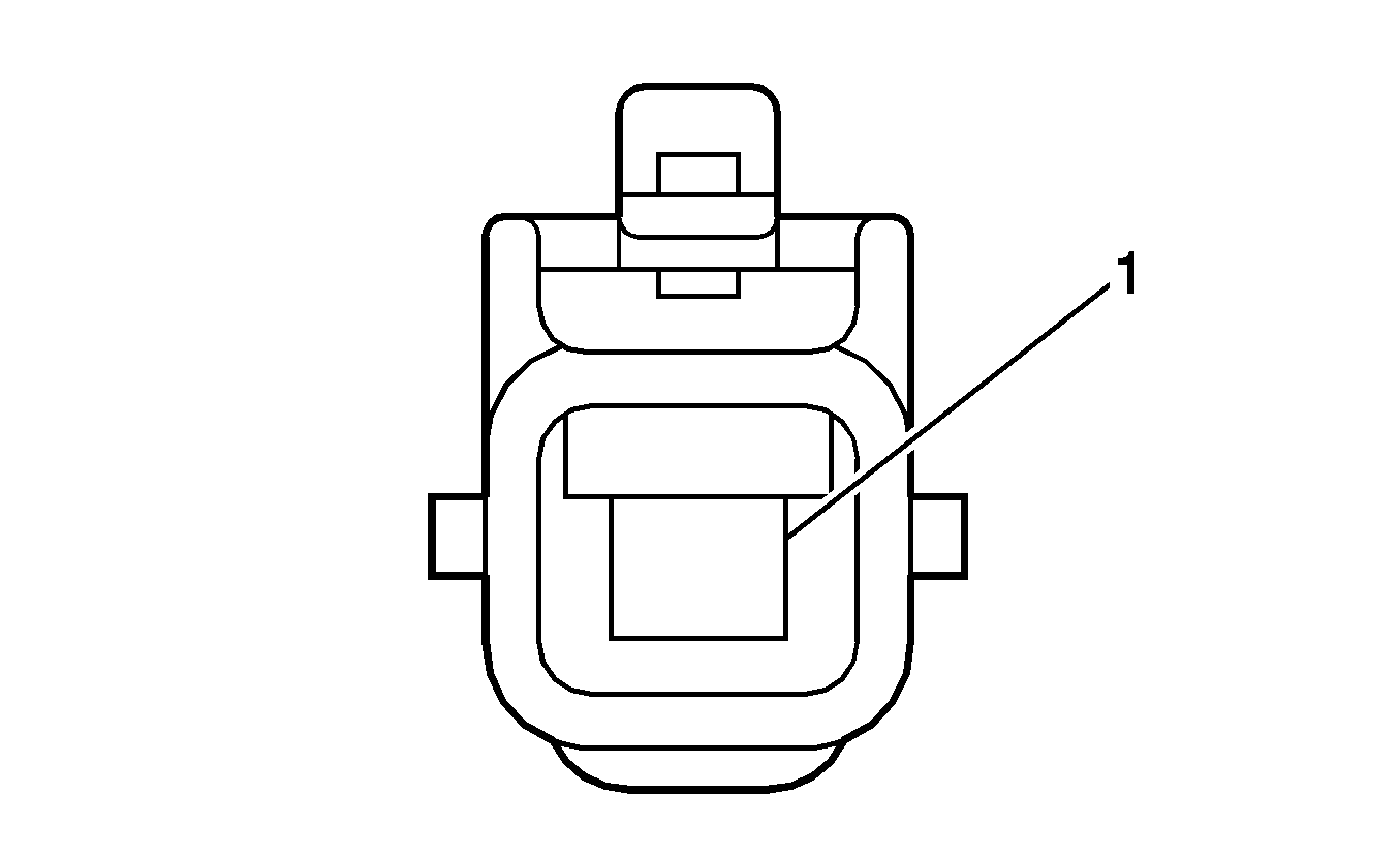
Connector Part Information
|
Pin | Wire | Circuit | Function |
|---|---|---|---|
1 | 3.0 D-BU | -- | Starter Solenoid Crank Voltage |
Starter Diode (LAY)
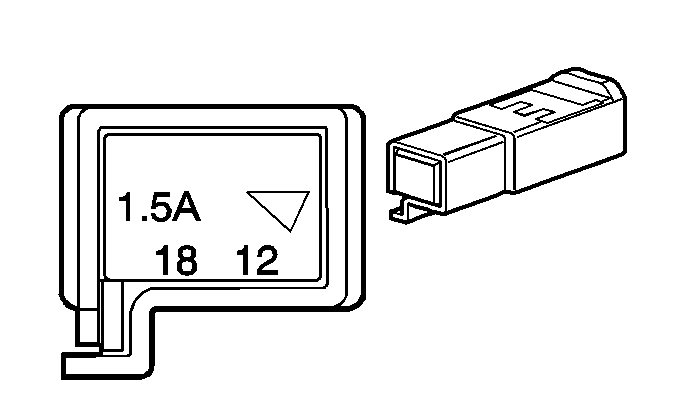
Connector Part Information
|
Pin | Wire | Circuit | Function |
|---|---|---|---|
1 | 0.35 BK | -- | Ignition Voltage |
2 | 0.35 WH | -- | Ignition Voltage |
Steering Angle Sensor
Connector Part Information
|
Pin | Wire | Circuit | Function |
|---|---|---|---|
1 | 0.35 WH/BK | -- | Ground |
2 | 0.35 WH | -- | High Speed GMLAN Serial Data Bus+ |
3 | 0.35 BN | -- | High Speed GMLAN Serial Data Bus- |
4 | 0.35 D-BU | -- | Ignition 1 Voltage |
5 | 0.35 RD | -- | Battery Positive Voltage |
Stop Lamp Switch
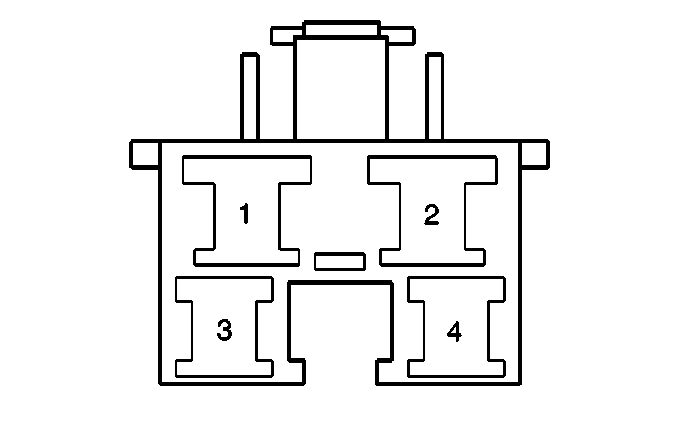
Connector Part Information
|
Pin | Wire | Circuit | Function |
|---|---|---|---|
1 | 0.85 L-BU | -- | Stop Lamp Switch Signal (Battery) |
2 | 0.85 WH | -- | Battery Positive Voltage |
3 | 0.3 BK | -- | Ignition 1 Voltage |
4 | 0.3 RD | -- | Stop Lamp Switch Signal (Ignition) |
Sunroof Control Module
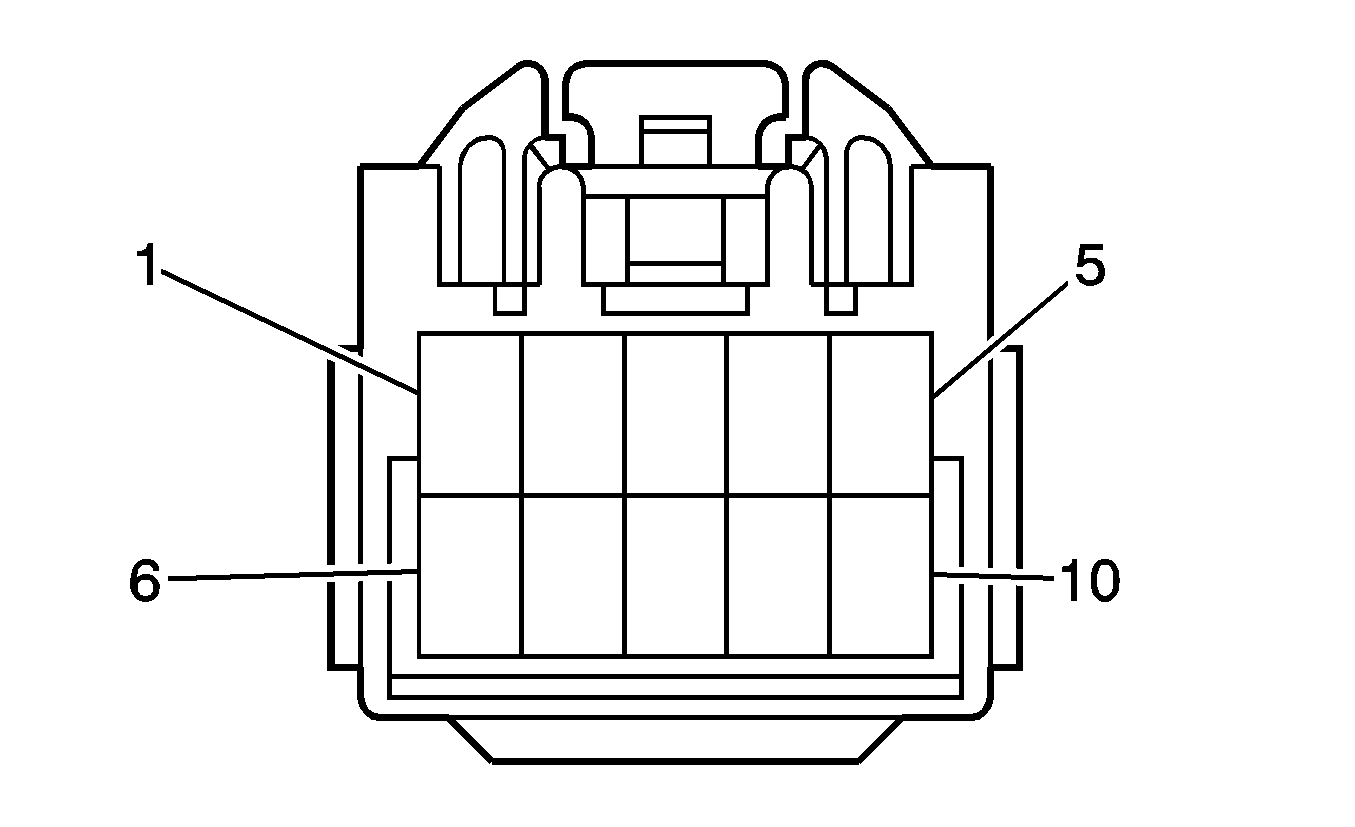
Connector Part Information
|
Pin | Wire | Circuit | Function |
|---|---|---|---|
1 | 0.35 D-GN | -- | Sunroof Switch Open Signal |
2 | 0.35 L-BU | -- | Sunroof Switch Close Signal |
3 | 1.0 YE | -- | Ignition 1 Voltage |
4 | -- | -- | Not Used |
5 | 1.0 WH/BK | -- | Ground |
6 | 0.35 RD | -- | Sunroof Switch Vent Signal |
7 | -- | -- | Not Used |
8 | 0.35 VT | -- | Vehicle Speed Signal |
9 | -- | -- | Not Used |
10 | 1.0 BG | -- | Battery Positive Voltage |
Tail Lamp - Left
Connector Part Information
|
Pin | Wire | Circuit | Function |
|---|---|---|---|
1 | 0.35 D-GN | -- | Park Lamp Supply Voltage |
2 | 0.5 D-BU | -- | Stop Lamp Supply Voltage |
3 | -- | -- | Not Used |
4 | 0.5 RD | -- | Backup Lamp Supply Voltage |
5 | 0.5 WH/BK | -- | Ground |
6 | 0.5 YE | -- | Flasher Relay Signal |
Tail Lamp - Right
Connector Part Information
|
Pin | Wire | Circuit | Function |
|---|---|---|---|
1 | 0.35 D-GN | -- | Park Lamp Supply Voltage |
2 | 0.5 D-BU | -- | Stop Lamp Supply Voltage |
3 | -- | -- | Not Used |
4 | 0.5 RD | -- | Backup Lamp Supply Voltage |
5 | 0.5 WH/BK | -- | Ground |
6 | 0.5 L-BU | -- | Flasher Relay Signal |
Theft Deterrent Alarm Siren
Connector Part Information
|
Pin | Wire | Circuit | Function |
|---|---|---|---|
1 | 0.35 D-GN | -- | Power Feed |
2-3 | -- | -- | Not Used |
4 | 0.35 L-BU | -- | Key Code Feed |
5 | 0.35 OG | -- | Data Transmit Feed |
6 | -- | -- | Not Used |
7 | 0.35 VT | -- | Ground |
Theft Deterrent Module (TDM) X1
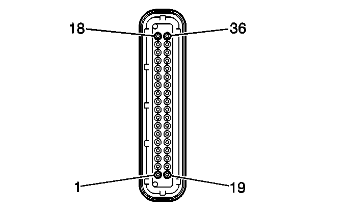
Connector Part Information
|
Pin | Wire | Circuit | Function |
|---|---|---|---|
1-2 | -- | -- | Not Used |
3 | 0.35 BG | -- | Glass Break ASW Sensor Signal |
4-6 | -- | -- | Not Used |
7 | 0.35 D-BU | -- | Key Switch Signal |
8 | -- | -- | Not Used |
9 | 0.35 D-BU | -- | Ignition 1 Voltage |
10 | -- | -- | Not Used |
11 | 0.35 RD | -- | Battery Positive Voltage |
12-15 | -- | -- | Not Used |
16 | 0.35 WH/BK | -- | Ground |
17-23 | -- | -- | Not Used |
24 | 0.35 L-GN | -- | Data Communication (-) |
25 | 0.35 WH | -- | Data Communication (+) |
26-28 | -- | -- | Not Used |
29 | 0.35 YE | -- | Security Indicator Lamp Supply Voltage |
30-36 | -- | -- | Not Used |
Theft Deterrent Module (TDM) X2
Connector Part Information
|
Pin | Wire | Circuit | Function |
|---|---|---|---|
1 | 0.35 BN | -- | Battery Positive Voltage |
2 | 0.35 BK | -- | Ignition 1 Voltage |
3 | 0.35 D-BU | -- | Ignition Key Switch Signal |
4 | 0.35 BG | -- | Data Transmit Feed |
5 | 0.35 VT | -- | Ground |
6 | -- | -- | Not Used |
7 | 0.35 RD | -- | Driver Door Jamb Switch Signal |
8 | 0.35 YE | -- | Security Indicator Lamp Control |
9 | 0.35 WH | -- | Data Link |
10 | -- | -- | Not Used |
11 | 0.35 WH/BK | -- | Ground |
12 | 0.35 L-GN | -- | Immobilizer Signal Out |
13 | 0.35 PK | -- | Immobilizer Signal in |
14 | 0.35 OG | -- | Power Feed |
15 | 0.35 L-BU | -- | Key Code Feed |
16 | 0.35 BN | -- | Ground |
Theft Deterrent Shock Sensor
Connector Part Information
|
Pin | Wire | Circuit | Function |
|---|---|---|---|
1 | 0.35 RD | -- | Battery Positive Voltage |
2 | -- | -- | Not Used |
3 | 0.35 D-BU | -- | Ignition Voltage |
4 | -- | -- | Not Used |
5 | 0.35 BG | -- | Shock Sensor Signal |
6 | 0.35 WH/BK | -- | Ground |
7 | 0.35 YE | -- | Microphone Signal (-) |
8 | 0.35 BK | -- | Microphone Signal (+) |
Theft Deterrent Shock Sensor Microphone
Connector Part Information
|
Pin | Wire | Circuit | Function |
|---|---|---|---|
A-B | -- | -- | Not Used |
C | 0.35 BK | -- | Microphone Signal (+) |
D | 0.35 YE | -- | Microphone Signal (-) |
Throttle Body
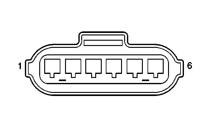
Connector Part Information
|
Pin | Wire | Circuit | Function |
|---|---|---|---|
1 | 0.5 BU | -- | TAC Motor Control - 2 |
2 | 0.5 PK | -- | TAC Motor Control - 1 |
3 | 0.5 BN | -- | Low Reference |
4 | 0.5 RD/D-GN | -- | TP Sensor 2 Signal (LAY) |
0.5 RD | -- | TP Sensor 2 Signal (LAX) | |
5 | 0.5 YE | -- | 5-Volt Reference |
6 | 0.5 L-GN | -- | TP Sensor 1 Signal |
Tire Pressure Indicator Reset Switch
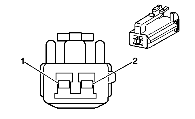
Connector Part Information
|
Pin | Wire | Circuit | Function |
|---|---|---|---|
1 | 0.35 L-BU | -- | Tire Pressure Reset Switch Signal |
2 | 0.35 WH/BK | -- | Ground |
Tire Pressure Module
Connector Part Information
|
Pin | Wire | Circuit | Function |
|---|---|---|---|
1 | 0.35 L-BU | -- | Tire Pressure Reset Switch Signal |
2 | 0.35 VT | -- | Vehicle Speed Sensor |
3 | 0.35 D-GN | -- | Low Speed Serial Data |
4 | 0.35 GY | -- | Engine Speed Signal |
5 | 0.35 PK | -- | Tire Pressure Indicator Control |
6 | 0.35 BK | -- | 5-Volt Reference |
7 | 0.35 D-BU | -- | Ignition 1 Voltage |
8 | -- | -- | Not Used |
9 | 0.35 BN | -- | Ground |
10 | 0.35 WH | -- | Low Speed Serial Data |
11 | 0.35 L-GN | -- | Ground |
12 | 0.35 RD | -- | Tire Pressure Receiver Signal |
Tire Pressure Receiver - Left Rear
Connector Part Information
|
Pin | Wire | Circuit | Function |
|---|---|---|---|
1 | 0.35 RD | -- | Tire Pressure Receiver Signal |
2-3 | -- | -- | Not Used |
4 | 0.35 L-GN | -- | Ground |
5 | 0.35 BK | -- | 5-Volt Reference |
Transfer Case Clutch Coil (F46)
Connector Part Information
|
Pin | Wire | Circuit | Function |
|---|---|---|---|
1 | 0.5 WH | -- | Transfer Case Clutch Control - High |
2 | 0.5 BK | -- | Transfer Case Clutch Control - Low |
Transfer Case Shift Control Module (F46)
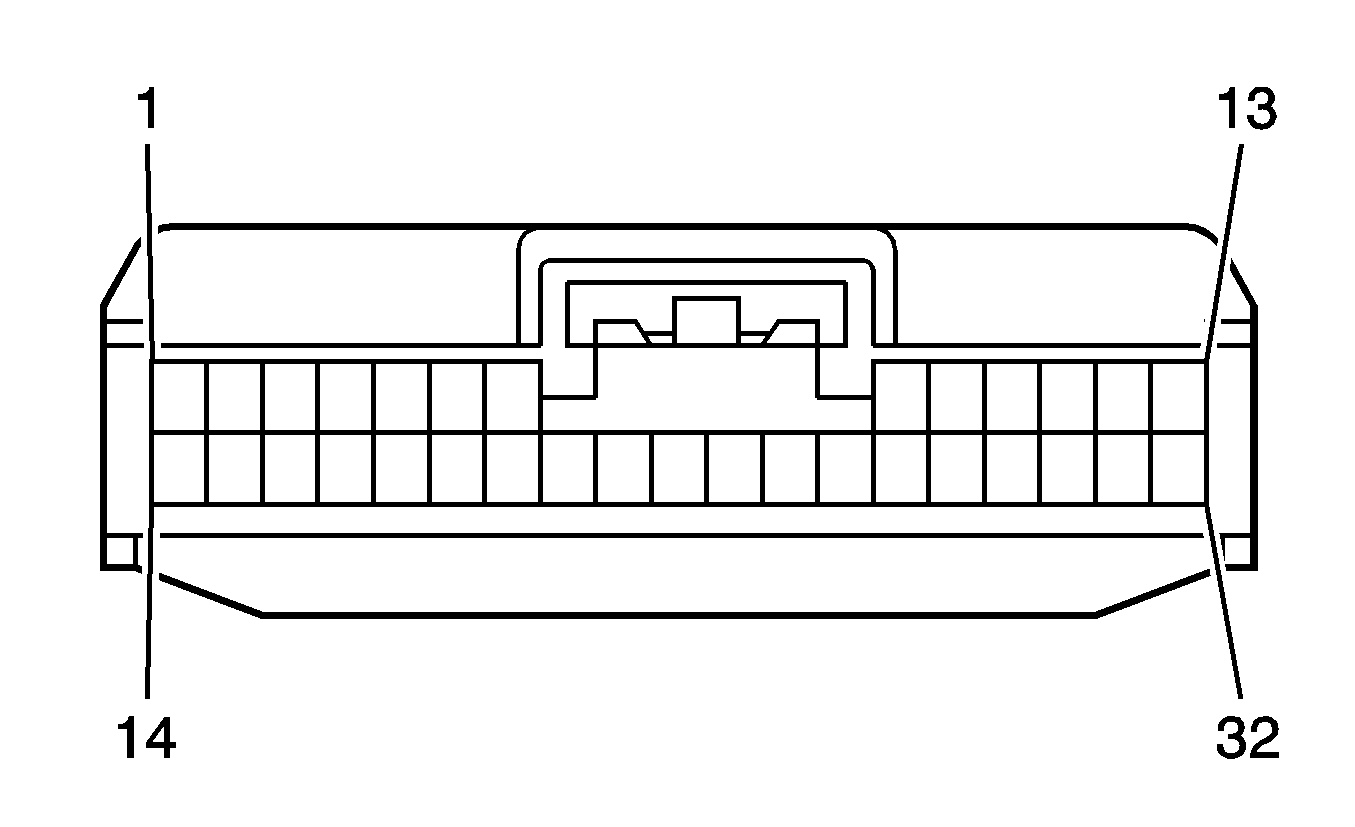
Connector Part Information
|
Pin | Wire | Circuit | Function |
|---|---|---|---|
1-8 | -- | -- | Not Used |
9 | 0.35 RD | -- | Battery Positive Voltage |
10 | -- | -- | Not Used |
11 | 0.35 D-BU | -- | Ignition 1 Voltage |
12 | -- | -- | Not Used |
13 | 0.35 WH | -- | Transfer Case Clutch Control - High |
14 | 0.35 D-BU | -- | High Speed GMLAN Serial Data Bus- |
15 | -- | -- | Not Used |
16 | 0.35 WH | -- | High Speed GMLAN Serial Data Bus+ |
17-22 | -- | -- | Not Used |
23 | 0.5 WH/BK | -- | Ground |
24-30 | -- | -- | Not Used |
31 | 0.01 BARE | -- | Drain Wire |
32 | 0.35 BK | -- | Transfer Case Clutch Control - Low |
Transmission Connector (MVA/MVB)
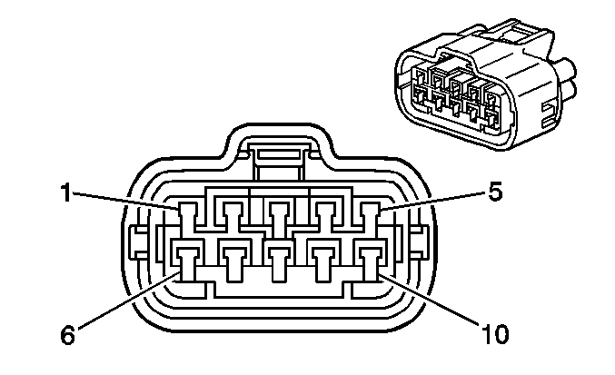
Connector Part Information
|
Pin | Wire | Circuit | Function |
|---|---|---|---|
1 | 0.5 YE | -- | TFT Sensor Signal (+) |
2 | 0.5 GY | -- | 5-Volt Reference (without MVA) |
0.5 L-GN | -- | 5-Volt Reference (MVA) | |
3 | 0.5 L-GN | -- | Shift Solenoid Valve S1 Control (without MVA) |
0.5 RD | -- | Shift Solenoid Valve S1 Control (MVA) | |
4 | 0.5 WH | -- | Shift Solenoid Valve SL2 High Control (without MVA) |
0.5 GY | -- | Shift Solenoid Valve SL2 High Control (MVA) | |
5 | 0.5 D-GN | -- | Shift Solenoid Valve SL1 High Control |
6 | 0.5 PK | -- | Low Reference |
7 | 0.5 VT | -- | Low Reference (MVA) |
8 | 0.5 VT | -- | Shift Solenoid Valve S2 Control (without MVA) |
0.5 WH | -- | Shift Solenoid Valve S2 Control (MVA) | |
9 | 0.5 BU | -- | Shift Solenoid Valve SL2 Control |
10 | 0.5 PK/D-GN | -- | Shift Solenoid Valve SLU Low Control |
Transmission Connector (MVD)
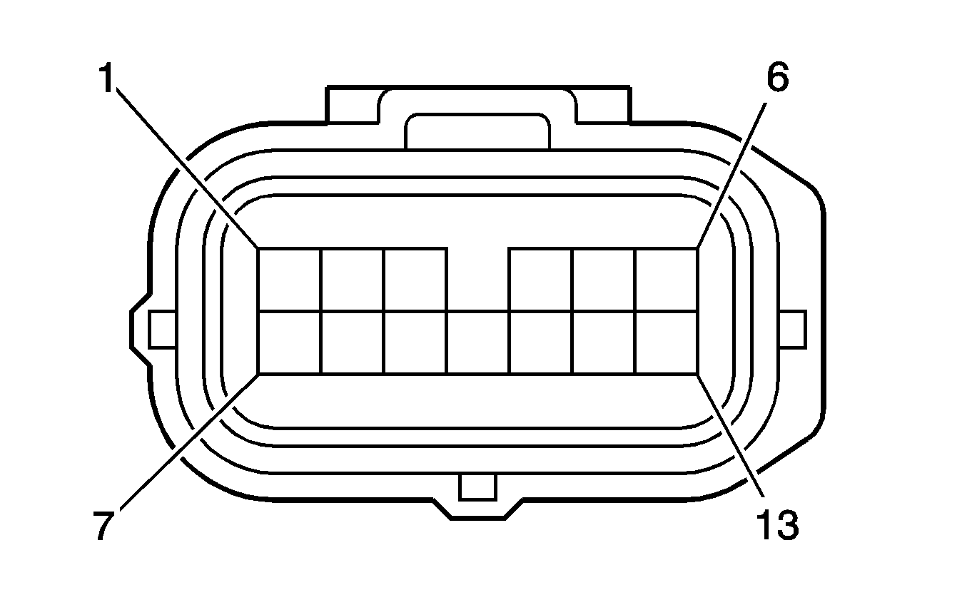
Connector Part Information
|
Pin | Wire | Circuit | Function |
|---|---|---|---|
1 | 0.5 YE | -- | TFT Sensor Signal |
2 | 0.5 L-GN | -- | Shift Solenoid Valve SLT High Control |
3 | 0.5 WH | -- | Shift Solenoid Valve SL1 Control |
4 | 0.5 VT | -- | Shift Solenoid Valve SL3 Control |
5 | 0.5 GY | -- | Shift Solenoid Valve ST |
6 | 0.5 D-GN | -- | Shift Solenoid Valve SLU High Control |
7 | 0.5 PK | -- | Low Reference |
8 | 0.5 VT | -- | Shift Solenoid Valve SLT Low Control |
9 | 0.5 YE | -- | Shift Solenoid Valve SL2 High Control |
10 | 0.5 RD | -- | Shift Solenoid Valve DSL Control |
11 | 0.5 BK | -- | Low Reference |
12 | 0.5 D-BU | -- | Shift Solenoid Valve SL2 Low Control |
13 | 0.5 PK/D-GN | -- | Shift Solenoid Valve SLU Low Control |
Turn Signal/Multifunction Switch
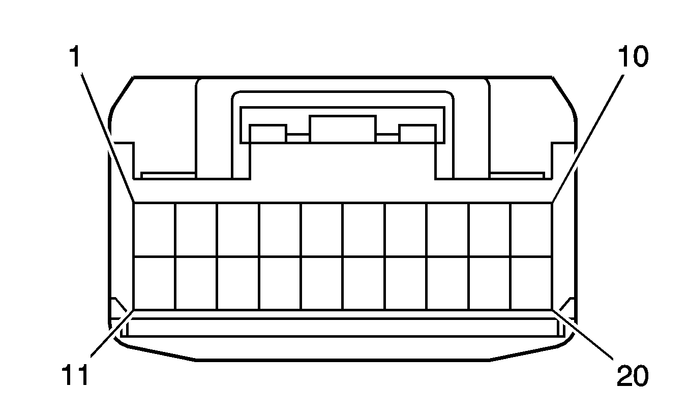
Connector Part Information
|
Pin | Wire | Circuit | Function |
|---|---|---|---|
1-2 | -- | -- | Not Used |
3 | 0.35 WH | -- | DRL Module - Low |
4 | 0.35 RD | -- | Fog Lamp Relay Control |
5-10 | -- | -- | Not Used |
11 | 0.35 L-GN | -- | High Beam Signal |
12 | 0.35 WH/BK | -- | Ground |
13 | 0.35 YE | -- | Right Turn Signal |
14 | -- | -- | Not Used |
15 | 0.35 PK | -- | Left Turn Signal |
16 | -- | -- | Not Used |
17 | 0.35 BK | -- | Headlamps Signal |
18 | 0.35 BN | -- | Parklamp/Headlamp Signal |
19 | -- | -- | Not Used |
20 | 0.35 D-GN | -- | Park Lamp Signal |
Vehicle Communication Interface Module (VCIM) X1
Connector Part Information
|
Pin | Wire | Function |
|---|---|---|
1 | 0.35 YE | Low Speed Serial Data |
2 | 0.35 L-GN | Rearview Mirror Indicator |
3 | 0.35 BG | Rearview Mirror Illumination |
4 | -- | Not Used |
5 | 0.5 BN | Ground |
6 | 0.35 RD | Accessory |
7 | 0.35 WH/BK | Ground |
8-10 | -- | Not Used |
11 | 0.35 L-BU | Signal |
12-14 | -- | Not Used |
15 | 0.35 PU | Battery Positive Voltage |
Vehicle Communication Interface Module (VCIM) X2
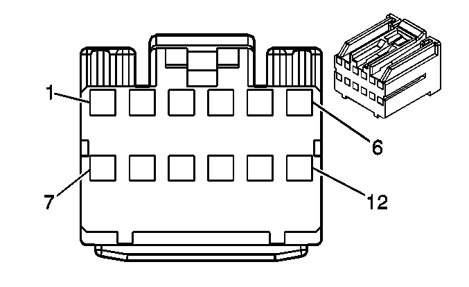
Connector Part Information
|
Pin | Wire | Function |
|---|---|---|
1 | 0.35 BK | Speaker Output Positive |
2 | 0.35 WH | Speaker Output Negative |
3-7 | -- | Not Used |
8 | BARE | Drain Wire |
9 | 0.35 RD | Microphone Positive |
10 | 0.35 D-GN | Microphone Negative |
11-12 | -- | Not Used |
Vehicle Communication Interface Module -- Auxiliary
Connector Part Information
|
Pin | Wire | Function |
|---|---|---|
1 | 0.35 YE | Antenna Signal |
2 | -- | Not Used |
3 | 0.35 D-BU | Right Front Door Lock Actuator Signal |
4 | 0.35 L-GN | Horn |
5 | 0.35 BG | Hazard Switch Signal |
6-8 | -- | Not Used |
9 | 0.5 L-BU | SIR Voltage |
10-11 | -- | Not Used |
12 | 0.35 GY | Battery Positive Voltage |
13 | 0.35 BK | Ignition Switch - Start Voltage |
14 | 0.35 PK | Battery Positive Voltage |
15 | 0.35 WH/BK | Ground |
16 | -- | Not Used |
Vehicle Stability Control (VSC) Module
Connector Part Information
|
Pin | Wire | Circuit | Function |
|---|---|---|---|
1-2 | -- | -- | Not Used |
3 | 0.35 WH/BK | -- | Ground |
4 | 0.35 WH | -- | Illumination (-) |
5 | 0.35 D-GN | -- | Illumination (+) |
6 | 0.35 GY | -- | Vehicle Stability Control Switch Input |
7-8 | -- | -- | Not Used |
Wheel Speed Sensor (WSS) - Left Front
Connector Part Information
|
Pin | Wire | Circuit | Function |
|---|---|---|---|
1 | 0.3 VT | -- | Left Front Wheel Speed Sensor Signal |
2 | 0.3 L-GN | -- | Left Front Wheel Speed Sensor Control |
Wheel Speed Sensor (WSS) - Left Rear
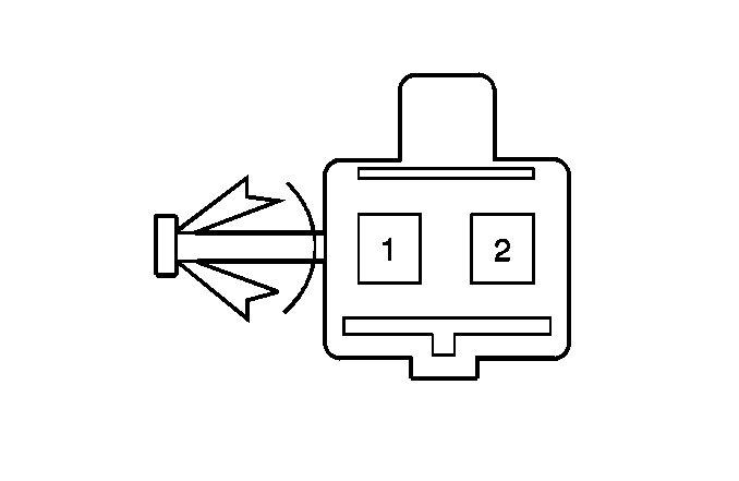
Connector Part Information
|
Pin | Wire | Circuit | Function |
|---|---|---|---|
1 | 0.35 BK | -- | Left Rear Wheel Speed Sensor Signal |
2 | 0.35 WH | -- | Left Rear Wheel Speed Sensor Control |
Wheel Speed Sensor (WSS) - Right Front
Connector Part Information
|
Pin | Wire | Circuit | Function |
|---|---|---|---|
1 | 0.3 L-GN | -- | Right Front Wheel Speed Sensor Signal |
2 | 0.3 BN | -- | Right Front Wheel Speed Sensor Control |
Wheel Speed Sensor (WSS) - Right Rear
Connector Part Information
|
Pin | Wire | Circuit | Function |
|---|---|---|---|
1 | 0.35 BK | -- | Right Rear Wheel Speed Sensor Signal |
2 | 0.35 WH | -- | Right Rear Wheel Speed Sensor Control |
Window Motor - Driver
Connector Part Information
|
Pin | Wire | Circuit | Function |
|---|---|---|---|
1 | 2.0 YE | -- | Window Motor - Up |
2 | 2.0 D-GN | -- | Window Motor - Down |
3-6 | -- | -- | Not Used |
Window Motor - Left Rear
Connector Part Information
|
Pin | Wire | Circuit | Function |
|---|---|---|---|
1 | 2.0 D-GN | -- | Window Motor - Up |
2 | 2.0 YE | -- | Window Motor - Down |
3-6 | -- | -- | Not Used |
Window Motor - Passenger
Connector Part Information
|
Pin | Wire | Circuit | Function |
|---|---|---|---|
1 | 2.0 BK | -- | Window Motor - Down |
2 | 2.0 D-BU | -- | Window Motor - Up |
3-6 | -- | -- | Not Used |
Window Motor - Right Rear
Connector Part Information
|
Pin | Wire | Circuit | Function |
|---|---|---|---|
1 | 2.0 RD | -- | Window Motor - Up |
2 | 2.0 D-GN | -- | Window Motor - Down |
3-6 | -- | -- | Not Used |
Window Switch - Left Rear
Connector Part Information
|
Pin | Wire | Circuit | Function |
|---|---|---|---|
1 | 2.0 YE | -- | Window Motor - Down |
2 | 2.0 D-BU | -- | Left Rear Window Motor (-) |
3 | 1.0 PK | -- | Window Motor - Power |
4 | 2.0 D-GN | -- | Window Motor - Up |
5 | 2.0 RD | -- | Left Rear Window Motor (+) |
Window Switch - Passenger
Connector Part Information
|
Pin | Wire | Circuit | Function |
|---|---|---|---|
1 | 2.0 BK | -- | Window Motor - Down |
2 | 2.0 BN | -- | Right Front Window Motor (-) |
3 | 1.0 YE | -- | Window Motor - Power |
4 | 2.0 D-BU | -- | Window Motor - Up |
5 | 2.0 D-GN | -- | Right Front Window Motor (+) |
Window Switch - Right Rear
Connector Part Information
|
Pin | Wire | Circuit | Function |
|---|---|---|---|
1 | 2.0 D-GN | -- | Window Motor - Down |
2 | 2.0 YE | -- | Right Rear Window Motor (-) |
3 | 1 BG | -- | Window Motor - Power |
4 | 2.0 RD | -- | Window Motor - Up |
5 | 2.0 BK | -- | Right Rear Window Motor (+) |
Windshield Washer Fluid Pump -- Front
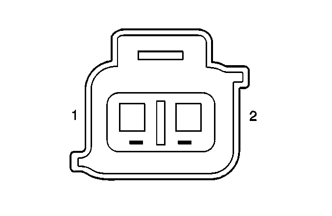
Connector Part Information
|
Pin | Wire | Circuit | Function |
|---|---|---|---|
1 | 0.85 BU | -- | Ignition 1 Voltage |
2 | 0.85 WH | -- | Washer Pump Control |
Windshield Washer Fluid Level Switch
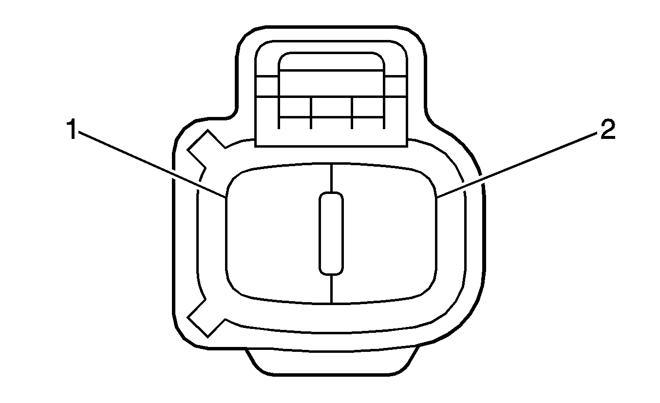
Connector Part Information
|
Pin | Wire | Circuit | Function |
|---|---|---|---|
1 | 0.3 OG | -- | Low Washer Fluid Indicator Control |
2 | 0.3 WH/BK | -- | Ground |
Windshield Wiper Motor
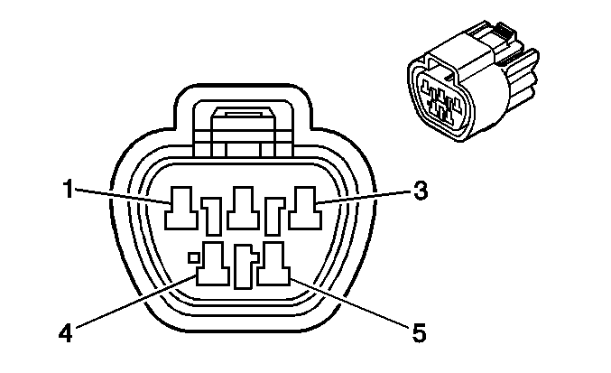
Connector Part Information
|
Pin | Wire | Circuit | Function |
|---|---|---|---|
1 | 2.0 D-GN | -- | Intermediate Speed Wiper Signal |
2 | 2.0 D-BU | -- | Battery Positive Voltage |
3 | 2.0 RD | -- | High Speed Wiper Signal |
4 | 2.0 WH/BK | -- | Ground |
5 | 2.0 BK | -- | Low Speed Wiper Signal |
Windshield Wiper/Washer Switch - Front X1
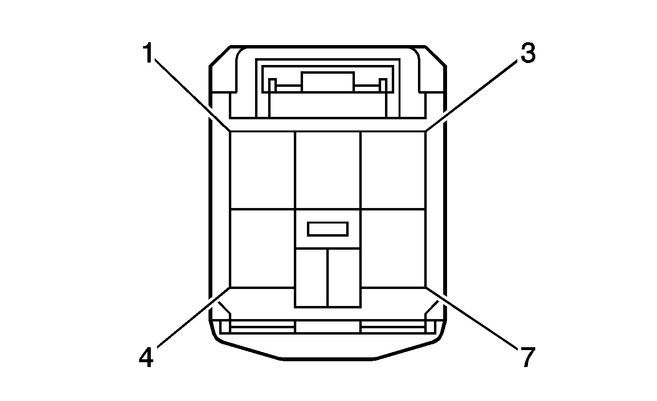
Connector Part Information
|
Pin | Wire | Circuit | Function |
|---|---|---|---|
1 | -- | -- | Not Used |
2 | 2.0 WH/BK | -- | Ground |
3 | 0.75 WH | -- | Washer Pump Control |
4 | -- | -- | Not Used |
5 | -- | -- | Not Used |
6 | 0.35 BN | -- | Rear Wiper - Common |
7 | 0.35 PK | -- | Rear Wiper - Voltage |
Windshield Wiper/Washer Switch - Front X2
Connector Part Information
|
Pin | Wire | Circuit | Function |
|---|---|---|---|
1 | 1.25 D-GN | -- | Intermediate Speed Wiper Signal |
2 | 1.25 D-BU | -- | Ignition 1 Voltage |
3 | 1.25 BK | -- | Low Speed Wiper Signal |
4 | 1.25 RD | -- | High Speed Wiper Signal |
5 | 0.5 L-GN | -- | Ground |
6-10 | -- | -- | Not Used |
Yaw Rate and Lateral Accelerometer Sensor
Connector Part Information
|
Pin | Wire | Circuit | Function |
|---|---|---|---|
1 | 0.35 WH/BK | -- | Ground |
2 | 0.35 WH | -- | High Speed GMLAN Serial Data Bus- |
3 | 0.35 D-BU | -- | High Speed GMLAN Serial Data Bus+ |
4 | 0.35 D-BU | -- | Ignition 1 Voltage |
5-6 | -- | -- | Not Used |
