Tools Required
Removal Procedure
Caution: Refer to Battery Disconnect Caution in the Preface section.
- Disconnect the negative battery cable.
- Drain the cooling system. Refer to
Cooling System Draining and Filling
in Engine Cooling.
- Remove the accessory drive belt. Refer to
Drive Belt Replacement
.
- Remove the generator from the engine. Refer to
Generator Replacement
in Engine Electrical.
- Install the engine support fixture. Refer to
Engine Support Fixture
.
- Remove the engine mount. Refer to
Engine Mount Replacement
.
- Remove the cylinder head cover. Refer to
Cylinder Head Cover Replacement
.
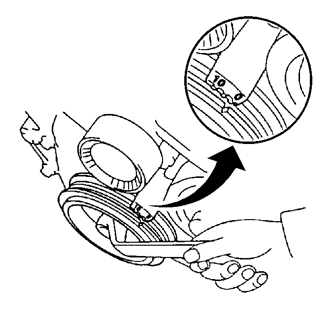
- Set the number 1 piston to the top dead center (TDC) position.
- Align the camshaft timing sprockets.
- Disconnect the power steering oil pressure switch connector.
- Raise the vehicle. Support the vehicle. Refer to
Lifting and Jacking the Vehicle
in General Information.
- Remove the right engine splash shield. Refer to
Engine Splash Shield Replacement - Right Side
in Body Front End.
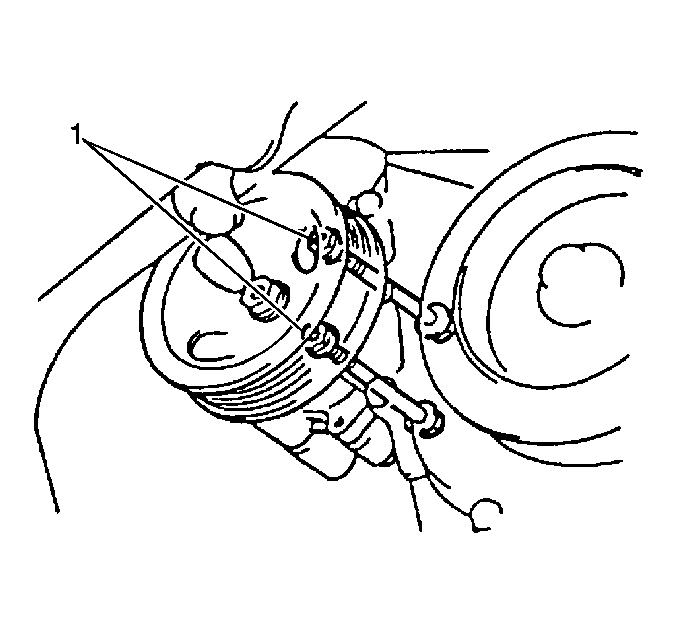
- Remove the 2 power steering pump through bolts and the nuts (1).
- Remove the power steering pump from the mounting surface.
Move the pump to the side.
- Remove the accessory drive belt. Refer to
Drive Belt Replacement
.
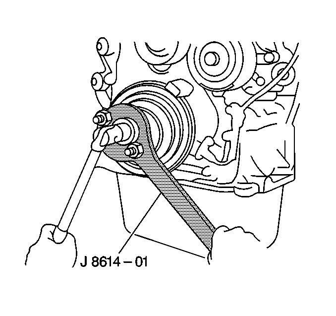
- Remove the crankshaft pulley retaining bolt using
J 8614-01
to prevent crankshaft rotation when loosening the bolt.
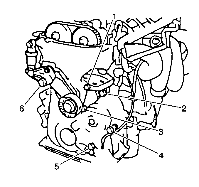
- Remove the following components:
| • | The crankshaft position sensor bolt (5) |
- Lower the vehicle.
- Remove the following components from the mounting surface:
| • | The drive belt tensioner bolt |
| • | The drive belt tensioner nut |
| • | The drive belt tensioner |
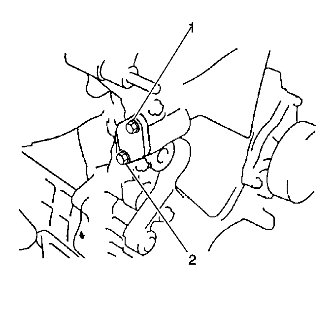
- Remove the timing chain tensioner bolts (1, 2).
- Remove the timing chain tensioner.
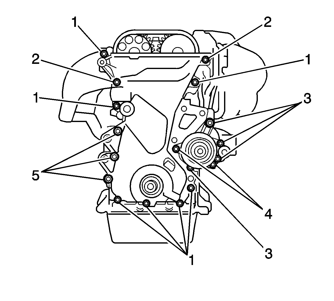
- Remove the following fasteners:
| • | The timing chain cover bolts (2-5) |
| • | The timing chain cover nuts (1) |
- Remove the timing chain cover.
Installation Procedure
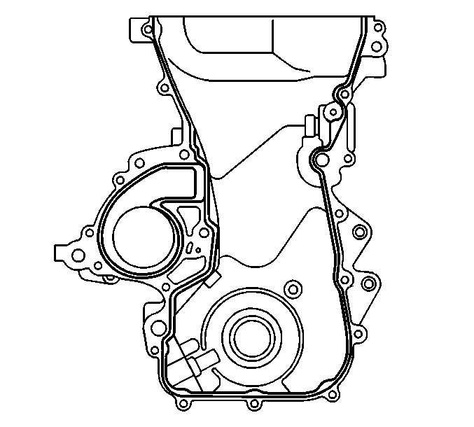
- Apply a continuous bead of GM P/N 12346240 (Canadian P/N 10953493) or an equivalent to the timing chain
cover mating surface.

- Install the timing chain cover water pump and o-ring.
Install the following fasteners and uniformly tighten the bolts
and nuts in several steps in order to secure the cover:
Tighten
| • | Tighten the timing chain cover bolts (1) (25 mm (0.98 in) length) to 13 N·m (10 lb in).
|
| • | Tighten the timing chain cover bolts (3) (35 mm (1.38 in) length) to 11 N·m (8 lb ft).
|
| • | Tighten the timing chain cover bolts (4) (30 mm (0.79 in) length) to 9 N·m (80 lb in).
|
| • | Tighten the timing chain cover bolts (5) (45 mm (1.77 in) length) to 19 N·m (14 lb ft).
|
| • | Tighten the timing chain cover nuts (1) to 10 N·m (89 lb in).
|
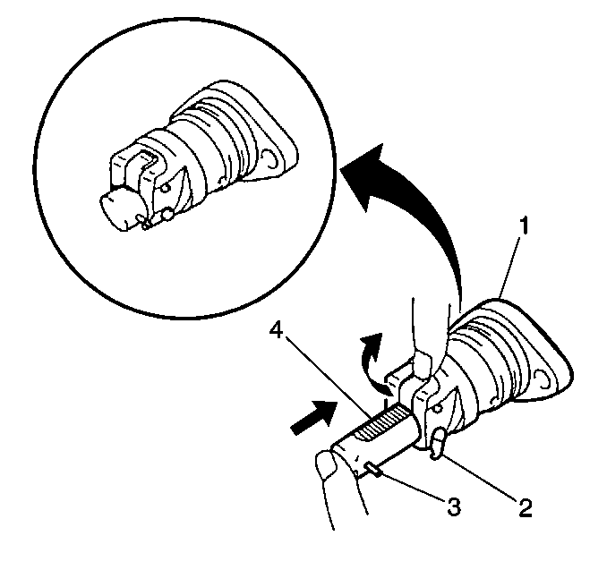
- Use the following steps in order to install the timing chain tensioner:
| 3.1. | Fully press the plunger (4). |
| 3.2. | Apply the hook (2) to the pin (3). |
| 3.3. | Install the timing chain tensioner. |
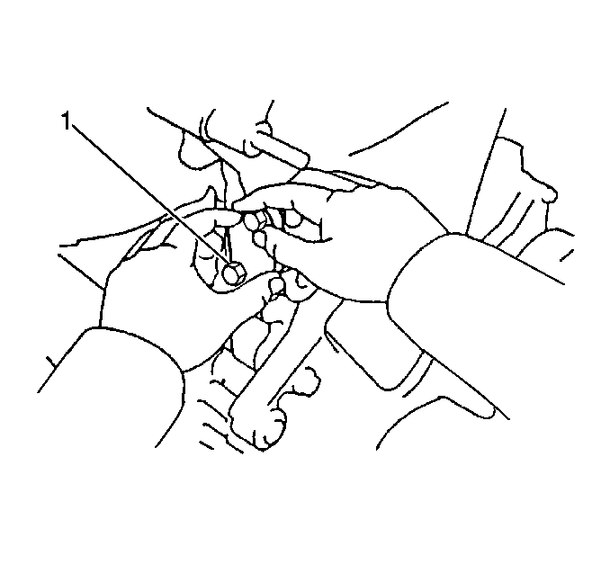
- Install the timing chain tensioner. Secure the timing chain tensioner using 2 bolts (1).
Tighten
Tighten the timing chain tensioner bolts to 10 N·m (89 lb in).

- Install the right side engine mounting bracket. Secure the bracket using 3 bolts.
Tighten
Tighten the engine mounting bracket bolts to 54 N·m (40 lb ft).
- Install the drive belt tensioner. Secure the tensioner using 1 bolt and 1 nut.
Tighten
| • | Tighten the bolt to 69 N·m (51 lb ft). |
| • | Tighten the nut to 29 N·m (21 lb ft). |
- Raise and properly support the vehicle. Refer to
Lifting and Jacking the Vehicle
in General Information.
- Install the crankshaft position sensor. Secure the sensor using 1 bolt (5).
Tighten
Tighten the crankshaft position sensor bolt to 12 N·m (106 lb in).
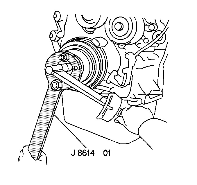
- Lubricate the front seal and the sealing surface of the crankshaft pulley with Chassis Grease GM P/N 1051344 (Canadian P/N 993037)
or equivalent.
- Install the crankshaft pulley onto the crankshaft indexing keyway.
- Install the crankshaft pulley retaining bolt using
J 8614-01
to prevent crankshaft rotation when tightening the bolt.
Tighten
Tighten the bolt to 142 N·m (105 lb ft).

- Install the power steering pump.
- Use the following fasteners in order to secure the power steering pump:
Tighten
Tighten the power steering pump bolts to 37 N·m (27 lb ft).
- Install the right engine splash shield. Refer to
Engine Splash Shield Replacement - Left Side
in Body Front End.
- Lower the vehicle.
- Connect the power steering oil pressure switch connector.
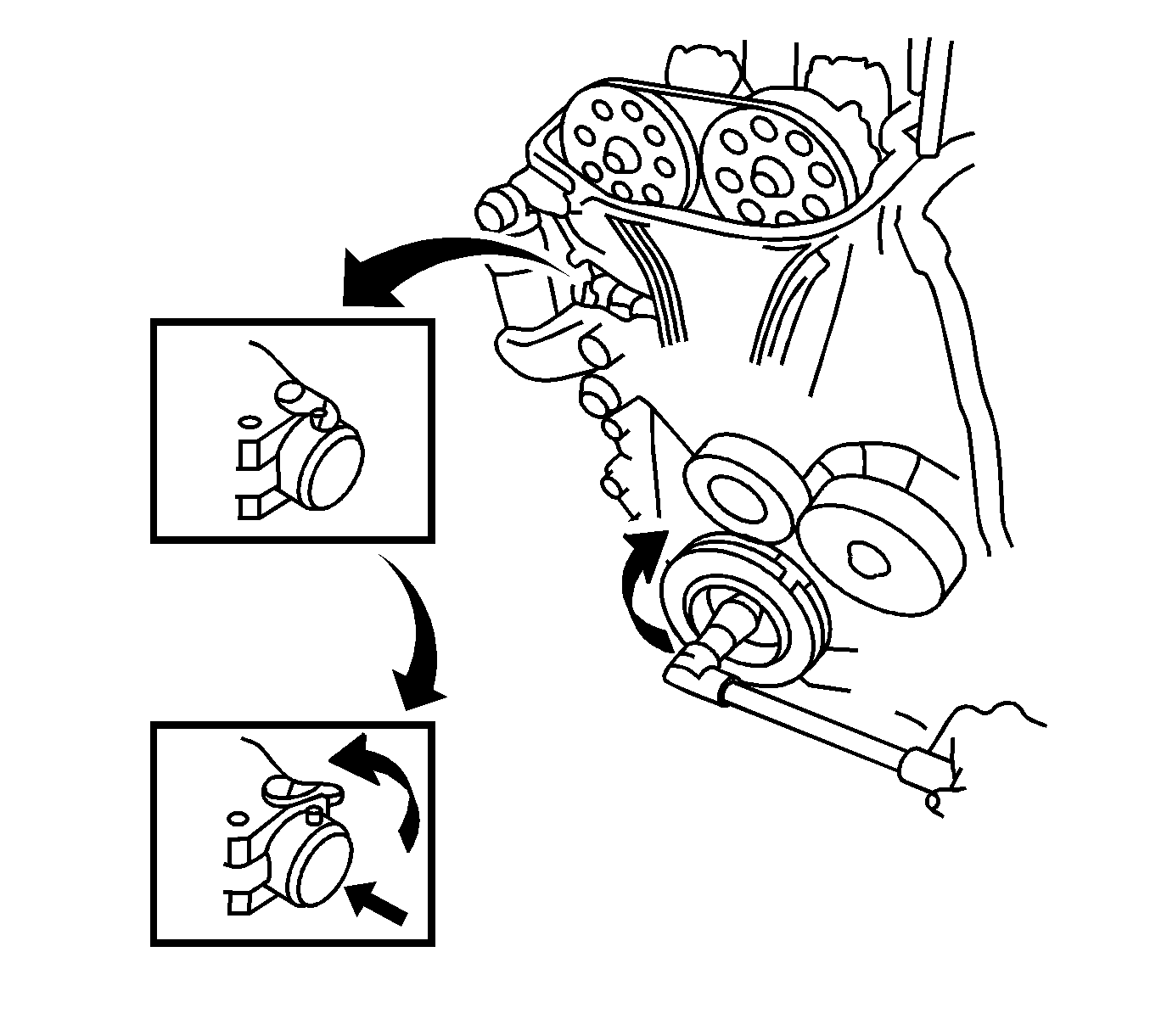
- Rotate the crankshaft clockwise 1 revolution. Ensure that the plunger on the timing chain tensioner has released.
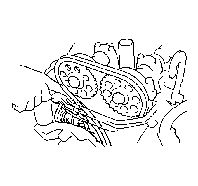
- Complete the following steps if the plunger does not release:
| 18.1. | Use a screwdriver or your finger in order to press the timing chain dampener into the timing chain tensioner. |
| 18.2. | Release the hook from the pin. |
| 18.3. | Verify proper timing chain alignment after the plunger has released. |
- Install the cylinder head cover. Refer to
Cylinder Head Cover Replacement
.
- Install the engine mount. Refer to
Engine Mount Replacement
.
- Remove the engine support fixture. Refer to
Engine Support Fixture
.
- Install the generator. Refer to
Generator Replacement
in Engine Electrical.
- Fill the cooling system. Refer to
Cooling System Draining and Filling
in Engine Cooling.
- Connect the negative battery cable.
Tighten
Tighten the battery cable bolt to 15 N·m (11 lb ft).


