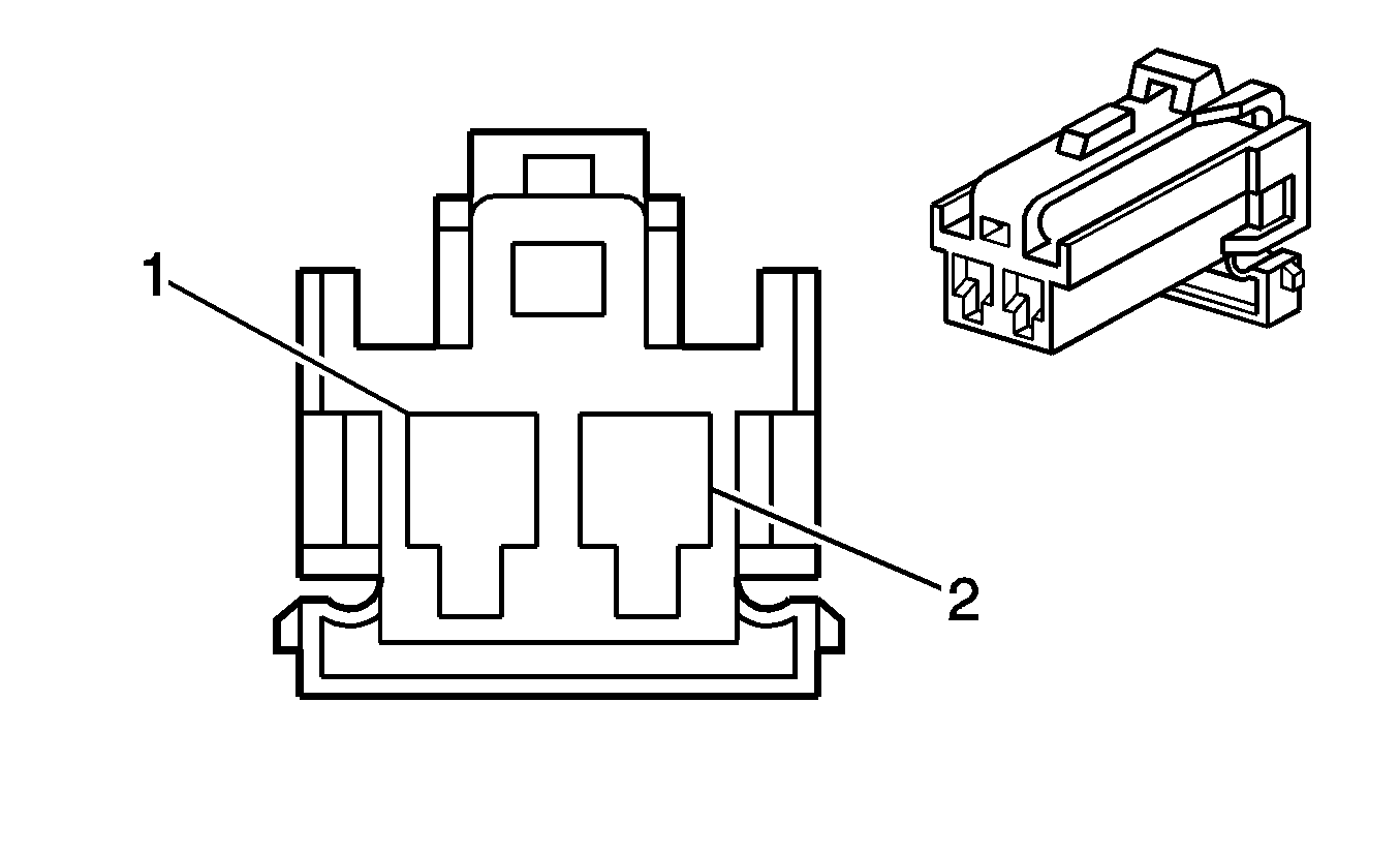
| Table 1: | Hood Ajar Switch |
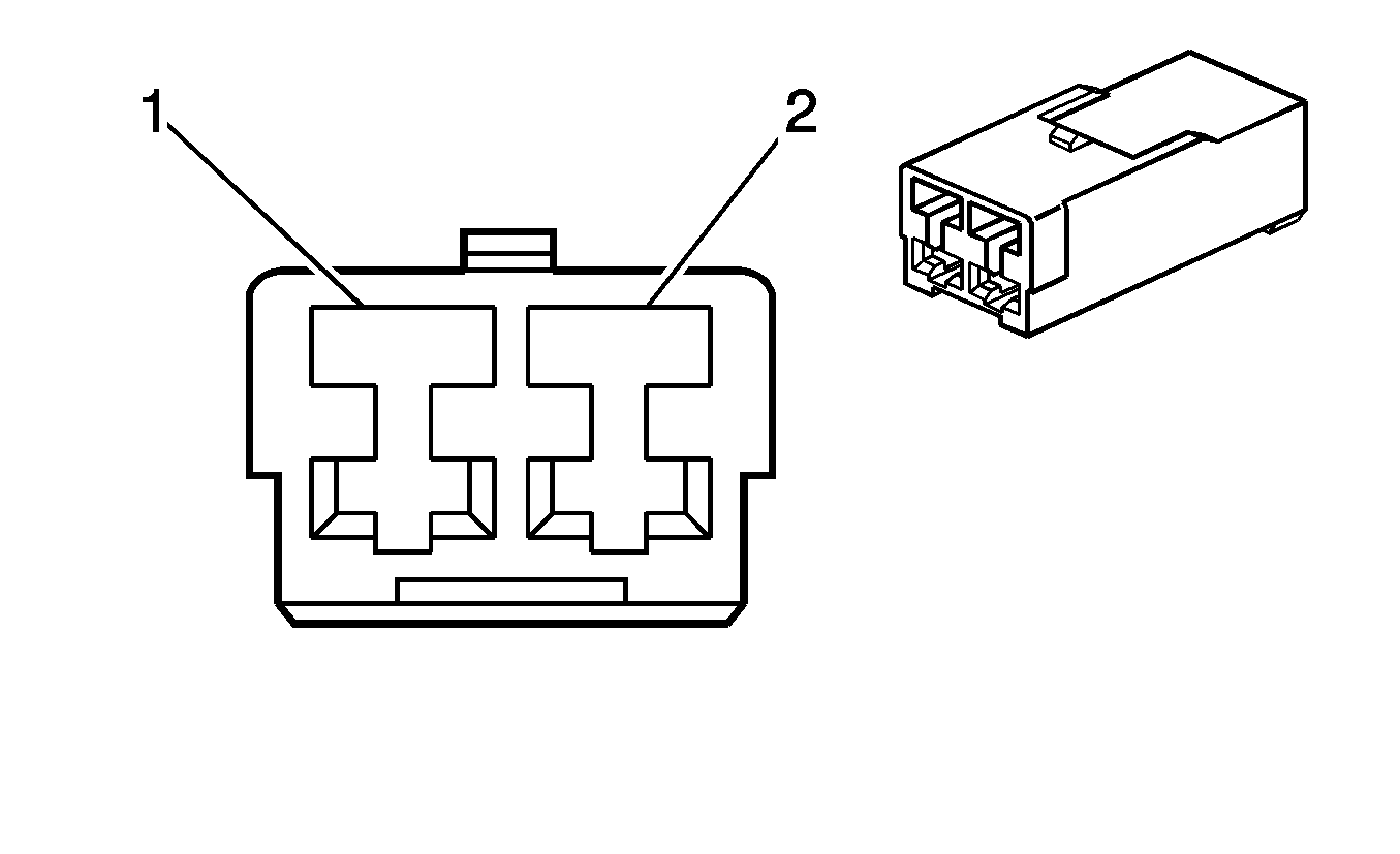
| Table 2: | Lock Cylinder Switch - Rear Compartment |
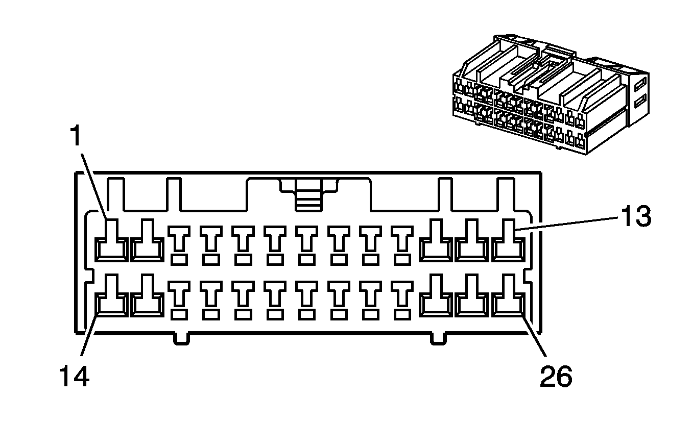
| Table 3: | Remote Control Door Lock Receiver (RCDLR) |
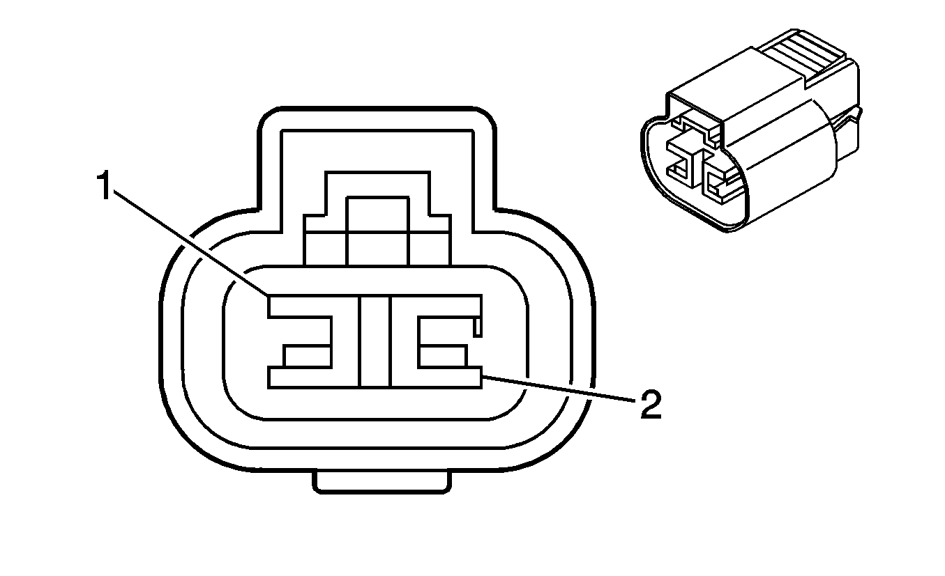
| Table 4: | Theft Deterrent Alarm |
| Table 5: | Theft Deterrent Control Module |
| |||||||
|---|---|---|---|---|---|---|---|
Connector Part Information |
| ||||||
Pin | Wire Color | Circuit No. | Function | ||||
1 | BN/BK | 109 | Hood Ajar Switch Signal | ||||
2 | OG | 1440 | Battery Positive Voltage | ||||
| |||||||
|---|---|---|---|---|---|---|---|
Connector Part Information |
| ||||||
Pin | Wire Color | Circuit No. | Function | ||||
1 | D-BU | 737 | Rear Compartment Lid Ajar Switch Signal | ||||
2 | BK | 850 | Ground | ||||
| |||||||
|---|---|---|---|---|---|---|---|
Connector Part Information |
| ||||||
Pin | Wire Color | Circuit No. | Function | ||||
1 | D-GN/WH | 261 | Arm Alarm Signal | ||||
2 | BK | 650 | Ground | ||||
3 | -- | -- | Not Used | ||||
4 | D-BU | 49 | Tamper Switch Signal (4 Door) | ||||
5 | OG/BK | 737 | Rear Compartment Lid Ajar Switch Signal | ||||
6 | -- | -- | Not Used | ||||
7 | BN/BK | 109 | Hood Ajar Switch Signal | ||||
8 | D-GN/WH | 157 | Courtesy Lamp Control | ||||
9 | GY | 195 | Door Lock Control | ||||
10 | GY/D-GN | 355 | Low Speed Cooling Fan Relay Control | ||||
11 | YE/D-GN | 356 | Driver Door Lock Relay Unlock Control | ||||
12 | D-BU | 49 | Tamper Switch Signal | ||||
13 | D-BU | 15 | Right Turn Signal Lamps Supply Voltage | ||||
14 | -- | -- | Not Used | ||||
15 | PK | 239 | Ignition 1 Voltage | ||||
16 | -- | -- | Not Used | ||||
17 | BK/WH | 2051 | Serial Data | ||||
18 | L-GN | 80 | Key In Ignition Switch Signal | ||||
19 | YE | 749 | Security Indicator Control | ||||
20 | D-BU | 49 | Tamper Switch Signal | ||||
21-24 | -- | -- | Not Used | ||||
25 | OG | 1340 | Battery Positive Voltage | ||||
26 | L-BU | 14 | Left Turn Signal Lamps Supply Voltage | ||||
| |||||||
|---|---|---|---|---|---|---|---|
Connector Part Information |
| ||||||
Pin | Wire Color | Circuit No. | Function | ||||
1 | D-GN/WH | 261 | Arm Alarm Signal | ||||
2 | BN | 641 | Ignition 3 Voltage | ||||
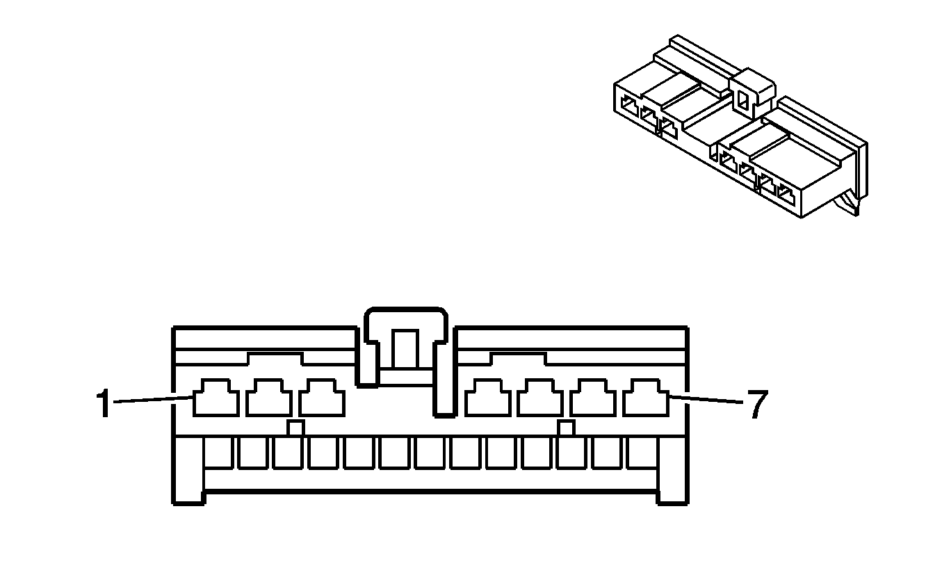
| |||||||
|---|---|---|---|---|---|---|---|
Connector Part Information |
| ||||||
Pin | Wire Color | Circuit No. | Function | ||||
1 | PK | 239 | Ignition 1 Voltage | ||||
2 | OG | 240 | Battery Positive Voltage | ||||
3 | -- | -- | Not Used | ||||
4 | BK | 450 | Ground | ||||
5 | D-BU/WH | 1800 | Battery Positive Voltage | ||||
6 | BK/WH | 2051 | Serial Data | ||||
7 | YE | 749 | Security Indicator Control | ||||
