Special Tools
SA9805E
/KM-796-A Fuel Line Separator
Removal Procedure
Important:
| • | The fuel tank must be drained with a suitable, commercially-available fuel removal unit and suction hose - follow safety regulations and national legislation. The fuel tank is fitted with a refill limit float valve. This is located on the filler
neck in the fuel tank. To prevent damaging the refill limit float valve, a suitable suction hose must be used. |
| • | In the presence of fuel vapors or escaping fuel - observe safety regulations and national legislation. Store drained fuel in a suitable, sealable container. |
- Open the hood.
Caution: Refer to Battery Disconnect Caution in the Preface section.
- Disconnect the battery.
- Disconnect the ground clamp from negative terminal.
Remove the nut
- Remove the right rear wheel.
- Raise the vehicle halfway.

- Remove the right rear wheel housing inner paneling.
Remove the 2 nuts (1) and 2 bolts (2).

- Disconnect the wiring harness of pressure sensor (atmospheric pressure) (1).
| • | Disconnect the wiring harness plug (2). |
| • | Disconnect 3 cable ties (3). |
- Raise the vehicle halfway.

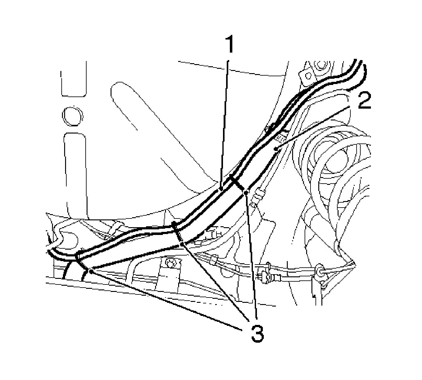
- Disconnect the wiring harness of pressure sensor (atmospheric pressure) (1) from the fuel filler tube (2).
- Disconnect 3 cable ties (3).
- Remove the complete exhaust system. Refer to
Exhaust System Replacement
.

- Disconnect the wiring harness plug of fuel tank fuel pump module (1).

- Disconnect the vent hose (3) from vent pipe (1).
- Disconnect the quick-release fitting (2) using
SA9805E
/KM-796-A .

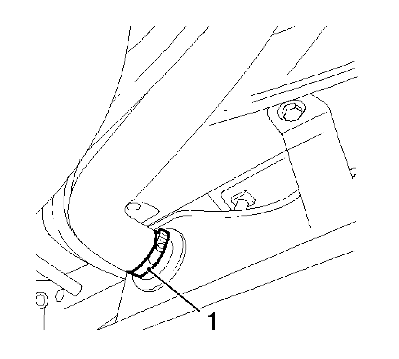
- Disconnect the fuel filler tube from the fuel tank.
Release the clamp (1).

- Disconnect the rear fuel lines (3, 5) from the middle fuel lines (1, 2).
- Disconnect the 2 quick-release fittings.
Press release (4).

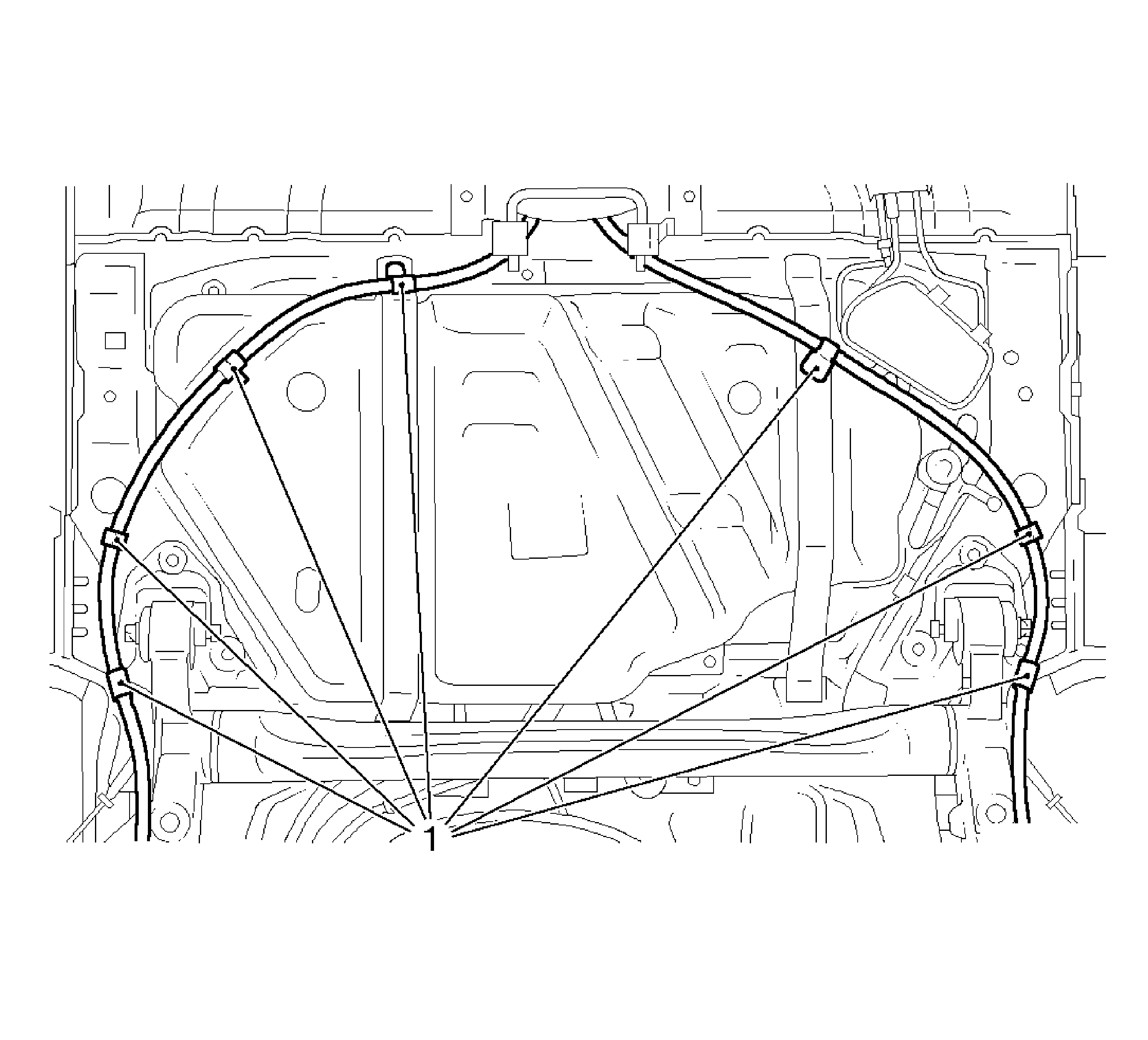
- Remove the parking brake cable from bracket (1) in 7 places.
- Retract the jack.

- Remove the 2 fuel tank holding straps.
Remove the 4 bolts (1).
Important: Wiring harness must be passed over rear axle.
- With the aid of an assistant, remove fuel tank.

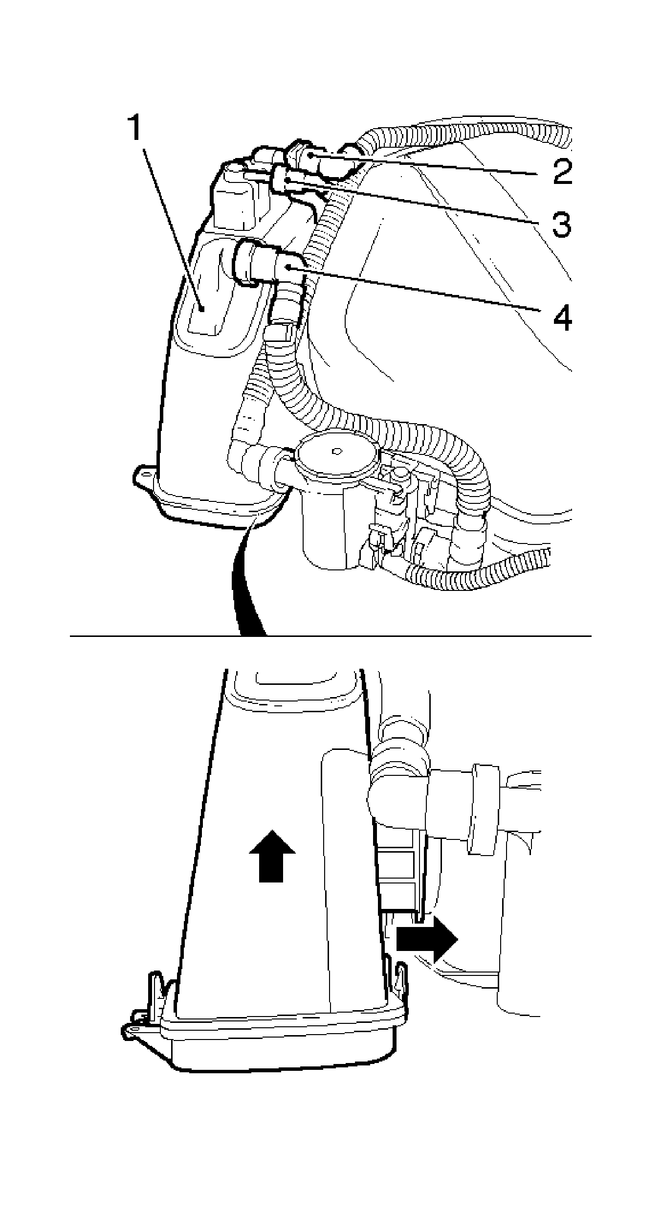
- Remove the evaporative emission canister (1).
| • | Remove the vent line from fuel tank to evaporative emission canister (2). |
| • | Disconnect the quick-release fitting. |
| • | Remove the vent line from evaporative emission canister to rear purge valve (4). |
| • | Disconnect the quick-release fitting. |
| • | Disconnect the rear vent line (3). |
| • | Disconnect the quick-release fitting. |
| • | Release the bracket and remove the evaporative emission canister. |
- Remove the rear vent line from the bracket.
Installation Procedure
- Install the rear vent line at bracket.
- Install the evaporative emission canister.
| • | Install the evaporative emission canister at bracket. |
| • | Install the rear vent line. |
| • | Connect the quick-release fitting. |
| • | Connect the vent line at evaporative emission canister to rear purge valve. |
| • | Connect the quick-release fitting. |
| • | Connect the vent line at fuel tank to evaporative emission canister. |
| • | Connect the quick-release fitting. |
- With the aid of an assistant, position the fuel tank to the vehicle.
Notice: Refer to Fastener Notice in the Preface section.
- Connect the 2 fuel tank holding straps.
Tighten
Tighten the 4 fuel tank holding strap bolts to 23 N·m (17 lb ft).
- Extend the jack.
- Install the parking brake cable to bracket in 7 places.
- Install the rear fuel lines to middle fuel lines.
Connect the 2 quick-release fittings.
- Install the fuel filler tube to fuel tank.
Tighten
Tighten the clamp to 3.5 N·m (31 lb in).
- Connect the vent hose to vent pipe.
Connect the quick-release fitting.
- Connect the wiring harness plug of fuel tank fuel pump module.
- Install the complete exhaust system. Refer to
Exhaust System Replacement
.
- Connect the wiring harness of pressure sensor (atmospheric pressure).
Connect the 3 cable ties.
- Lower the vehicle halfway.
- Connect the wiring harness of pressure sensor (atmospheric pressure).
| • | Connect the wiring harness plug. |
| • | Connect the 3 cable ties. |
- Install the right rear wheel housing inner paneling.
Install the 2 nuts and 2 bolts.
Tighten
| • | Tighten the 2 rear wheel housing inner paneling nuts to 2.5 N·m (22 lb in). |
| • | Tighten the 2 rear wheel housing inner paneling bolts to 2.5 N·m (22 lb in). |
- Mount the right rear wheel .
- Lower the vehicle halfway.
Tighten
Tighten the right rear wheel bolts to 110 N·m (81 lb ft).
- Connect the battery.
- Connect the ground clamp to negative terminal.
Tighten
Tighten the ground clamp nut to 5 N·m (44 lb in).
- For programming procedures, refer to
Control Module References
.
- Close the hood.


