X100 Transmission Harness to Automatic Transmission Harness (MNF)

|

|
Connector Part Information
| Connector Part Information
|
Terminal Part Information
| Terminal Part Information
|
Pin | Wire Color | Circuit No. | Function | Pin | Wire Color | Circuit No. | Function |
|---|---|---|---|---|---|---|---|
1 | 0.5 BK/GN | 1525 | Shift Solenoid Supply Voltage 1 | 1 | 0.5 WH | 1525 | Shift Solenoid Supply Voltage 1 |
2 | 0.5 BK/WH | 1527 | Shift Solenoid Supply Voltage 3 | 2 | 0.5 RD | 1527 | Shift Solenoid Supply Voltage 3 |
3 | 0.5 WH/GN | 1530 | Transmission Mainline Pressure Solenoid Control | 3 | 0.5 OG | 1530 | Transmission Mainline Pressure Solenoid Control |
4 | 0.5 BK/BU | 585 | Transmission Oil Temperature Sensor Signal | 4 | 0.5 OG | 585 | Transmission Oil Temperature Sensor Signal |
5 | 0.5 YE/RD | 1230 | Transmission Speed Sensor Signal | 5 | 0.5 YE/BK | 1230 | Transmission Speed Sensor Signal |
6 | 0.5 YE/VT | 400 | Vehicle Speed Sensor Signal | 6 | 0.5 YE | 400 | Vehicle Speed Sensor Signal |
7-8 | -- | -- | Not Used | 7-8 | -- | -- | Not Used |
9 | 0.5 BK/VT | 1526 | Shift Solenoid Supply Voltage 2 | 9 | 0.5 BK | 1526 | Shift Solenoid Supply Voltage 2 |
10 | 0.5 WH/BK | 1994 | Shift Solenoid Control 4 | 10 | 0.5 YE | 1994 | Shift Solenoid Control 4 |
11 | 0.5 BU/WH | 5503 | Low Reference | 11 | 0.5 GN | 5503 | Low Reference |
12 | 0.5 BN/BK | 586 | Low Reference | 12 | 0.5 OG | 586 | Low Reference |
13 | 0.5 YE/BK | 1231 | Low Reference | 13 | 0.5 GN | 1231 | Low Reference |
14 | 0.5 YE/BN | 401 | Low Reference | 14 | 0.5 GY | 401 | Low Reference |
15 | 0.5 BN/GN | 2879 | Low Reference | 15 | 0.5 TN | 2879 | Low Reference |
16 | -- | -- | Not Used | 16 | -- | -- | Not Used |
X101 Body Harness to Left Front Wheel Speed Sensor Harness
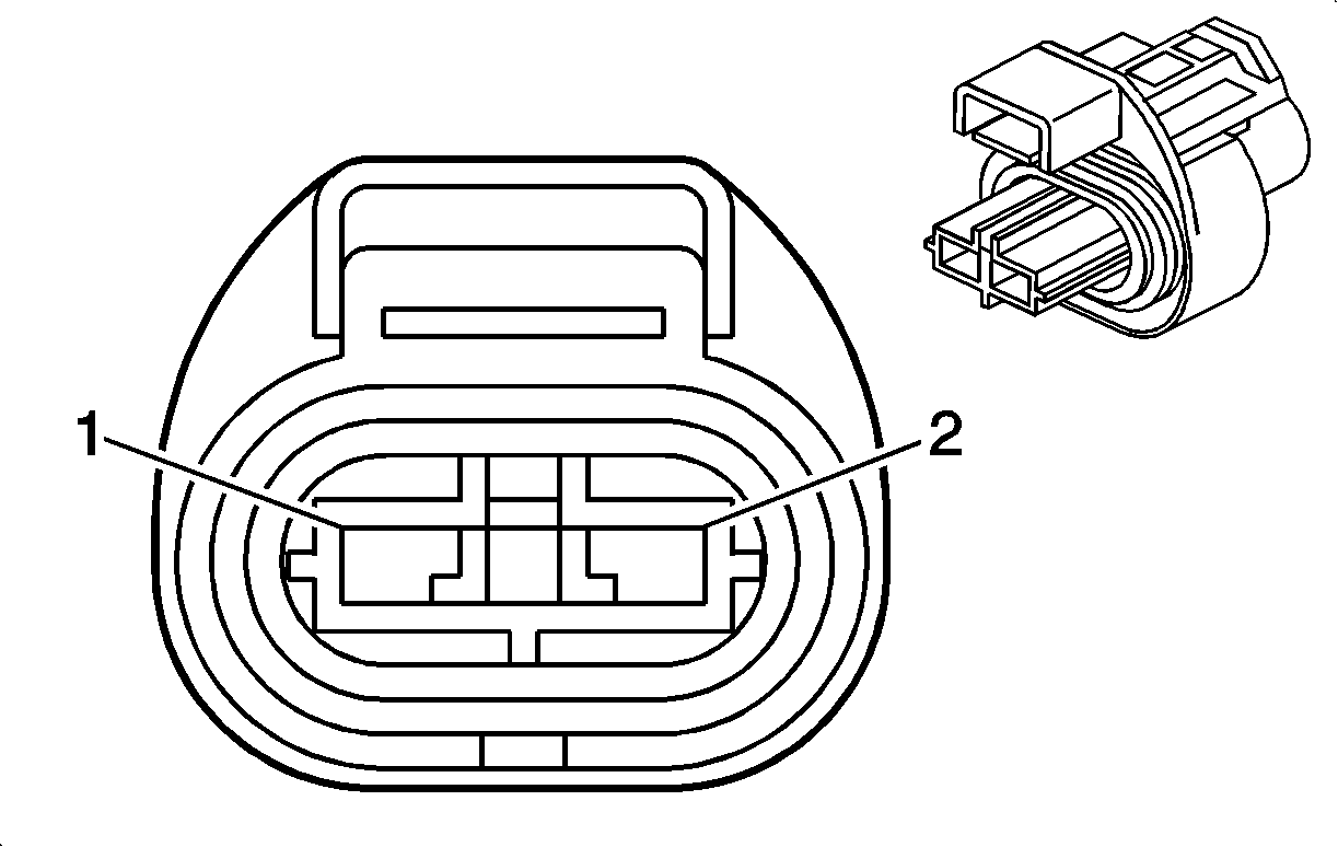
|

|
Connector Part Information
| Connector Part Information
|
Terminal Part Information
| Terminal Part Information
|
Pin | Wire Color | Circuit No. | Function | Pin | Wire Color | Circuit No. | Function |
|---|---|---|---|---|---|---|---|
1 | 0.5 BU/WH | 830 | Wheel Speed Sensor Signal Left Front | 1 | 0.5 BU/WH | 830 | Wheel Speed Sensor Signal Left Front |
2 | 0.5 BN/WH | 873 | Low Reference | 2 | 0.5 BN/WH | 873 | Low Reference |
X102 Forward Lamp Harness to Right Front Wheel Speed Sensor Harness

|

|
Connector Part Information
| Connector Part Information
|
Terminal Part Information
| Terminal Part Information
|
Pin | Wire Color | Circuit No. | Function | Pin | Wire Color | Circuit No. | Function |
|---|---|---|---|---|---|---|---|
1 | 0.5 BU/RD | 872 | Wheel Speed Sensor Signal Right Front | 1 | 0.5 BU/RD | 872 | Wheel Speed Sensor Signal Right Front |
2 | 0.5 BN/RD | 833 | Low Reference | 2 | 0.5 BN/RD | 833 | Low Reference |
X103 Forward Lamp Harness to Left Headlamp Harness
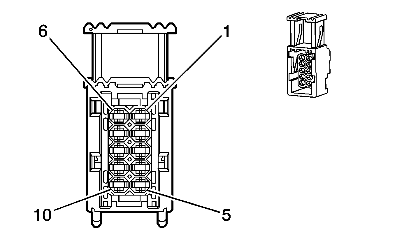
|
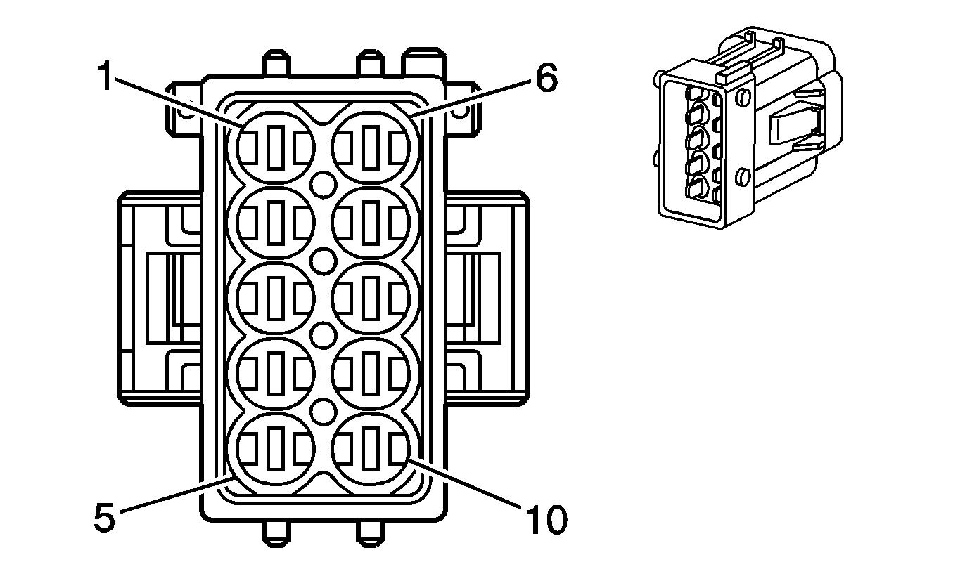
|
Connector Part Information
| Connector Part Information
|
Terminal Part Information
| Terminal Part Information
|
Pin | Wire Color | Circuit No. | Function | Pin | Wire Color | Circuit No. | Function |
|---|---|---|---|---|---|---|---|
1 | 1.5 BN | 1150 | Ground | 1 | BK | 1150 | Ground |
BK | 1150 | Ground | |||||
2 | 1 WH | 711 | Left Headlamp High Beam Supply Voltage | 2 | BK | 711 | Left Headlamp High Beam Supply Voltage |
3 | 1 YE | 712 | Left Headlamp Low Beam Supply Voltage | 3 | BK | 712 | Left Headlamp Low Beam Supply Voltage |
4 | 0.5 GY/BK | 709 | Left Park Lamp Supply Voltage | 4 | BK | 709 | Left Park Lamp Supply Voltage |
5 | 0.5 BK/WH | 1314 | Left Front Turn Signal Lamp Supply Voltage | 5 | BK | 1314 | Left Front Turn Signal Lamp Supply Voltage |
6-8 | -- | -- | Not Used | 6-8 | -- | -- | Not Used |
9 | 1.5 BN | 1150 | Ground | 9 | BK | 1150 | Ground |
10 | 1.5 BN | 1150 | Ground | 10 | BK | 1150 | Ground |
X104 Forward Lamp Harness to Right Headlamp Harness

|

|
Connector Part Information
| Connector Part Information
|
Terminal Part Information
| Terminal Part Information
|
Pin | Wire Color | Circuit No. | Function | Pin | Wire Color | Circuit No. | Function |
|---|---|---|---|---|---|---|---|
1 | 1.5 BN | 1050 | Ground | 1 | BK | 1050 | Ground |
BK | 1050 | Ground | |||||
2 | 1 WH | 311 | Right Headlamp High Beam Supply Voltage | 2 | BK | 311 | Right Headlamp High Beam Supply Voltage |
3 | 1 YE | 312 | Right Headlamp Low Beam Supply Voltage | 3 | BK | 312 | Right Headlamp Low Beam Supply Voltage |
4 | 0.5 GY/BK | 309 | Right Park Lamp Supply Voltage | 4 | BK | 309 | Right Park Lamp Supply Voltage |
5 | 0.5 BK/WH | 1315 | Right Front Turn Signal Lamp Supply Voltage | 5 | BK | 1315 | Right Front Turn Signal Lamp Supply Voltage |
6-8 | -- | -- | Not Used | 6-8 | -- | -- | Not Used |
9 | 1.5 BN | 1050 | Ground | 9 | BK | 1050 | Ground |
10 | 1.5 BN | 10150 | Ground | 10 | BK | 1050 | Ground |
X105 Forward Lamp Harness to Right Front Wheel Speed Sensor Harness

|

|
Connector Part Information
| Connector Part Information
|
Terminal Part Information
| Terminal Part Information
|
Pin | Wire Color | Circuit No. | Function | Pin | Wire Color | Circuit No. | Function |
|---|---|---|---|---|---|---|---|
1 | 0.5 BU/RD | 872 | Wheel Speed Sensor Signal Right Front | 1 | 0.5 BU/RD | 872 | Wheel Speed Sensor Signal Right Front |
2 | 0.5 BN/RD | 833 | Low Reference | 2 | 0.5 BN/RD | 833 | Low Reference |
X106 Power Steering Harness to Body Harness

|

|
Connector Part Information
| Connector Part Information
|
Terminal Part Information
| Terminal Part Information
|
Pin | Wire Color | Circuit No. | Function | Pin | Wire Color | Circuit No. | Function |
|---|---|---|---|---|---|---|---|
1 | 0.5 BK | 639 | Run/Crank Ignition 1 Voltage | 1 | 0.5 BK | 639 | Run/Crank Ignition 1 Voltage |
2 | 0.75 GN | 2500 | High Speed GMLAN Serial Data (+) (NS2/NR1) | 2 | 0.75 GN | 2500 | High Speed GMLAN Serial Data (+) |
3 | 0.75 WH | 2501 | High Speed GMLAN Serial Data (-) (NS2/NR1) | 3 | 0.75 WH | 2501 | High Speed GMLAN Serial Data (-) |
4 | 0.5 GN/WH | 377 | Serial Data (- NS2/NR1) | 4 | 0.5 GN/WH | 377 | Serial Data |
5 | 0.5 BU/WH | 225 | Generator Turn On Signal (- NS2/NR1) | 5 | 0.5 BU/WH | 225 | Generator Turn On Signal |
X107 Body Harness to Forward Lamp Harness

|

|
Connector Part Information
| Connector Part Information
|
Terminal Part Information
| Terminal Part Information
|
Pin | Wire Color | Circuit No. | Function | Pin | Wire Color | Circuit No. | Function |
|---|---|---|---|---|---|---|---|
1-6 | -- | -- | Not Used | 1-6 | -- | -- | Not Used |
7 | 0.5 YE/GY | 6776 | Middle Front Impact Sensing Module 2 Supply Voltage | 7 | 0.5 YE/GY | 6776 | Middle Front Impact Sensing Module 2 Supply Voltage |
8 | 0.5 GN/WH | 6777 | Middle Front Impact Sensing Module 2 Signal | 8 | 0.5 GN/WH | 6777 | Middle Front Impact Sensing Module 2 Signal |
9 | 0.5 BU/RD | 872 | Wheel Speed Sensor Signal Right Front | 9 | 0.5 BU/RD | 872 | Wheel Speed Sensor Signal Right Front |
10 | 0.5 BN/RD | 833 | Low Reference | 10 | 0.5 BN/RD | 833 | Low Reference |
11 | -- | -- | Not Used | 11 | -- | -- | Not Used |
12 | 0.5 BK/WH | 6168 | Middle Front Impact Sensing Module Supply Voltage | 12 | 0.5 BK/WH | 6168 | Middle Front Impact Sensing Module Supply Voltage |
13 | 0.5 OG/BK | 6169 | Middle Front Impact Sensing Module Signal | 13 | 0.5 OG/BK | 6169 | Middle Front Impact Sensing Module Signal |
14 | 0.5 BK/GN | 1415 | Right Front Turn Signal Switch Signal | 14 | 0.5 BK/GN | 1415 | Right Front Turn Signal Switch Signal |
15 | 0.5 BK/WH | 1414 | Left Front Turn Signal Switch Signal | 15 | 0.5 BK/WH | 1414 | Left Front Turn Signal Switch Signal |
16-32 | -- | -- | Not Used | 16-32 | -- | -- | Not Used |
33 | 2.5 RD | 342 | Battery Positive Voltage | 33 | 2.5 RD | 342 | Battery Positive Voltage |
34-48 | -- | -- | Not Used | 34-48 | -- | -- | Not Used |
X108 Body Harness to Engine and Transmission Harness

|

|
Connector Part Information
| Connector Part Information
|
Terminal Part Information
| Terminal Part Information
|
Pin | Wire Color | Circuit No. | Function | Pin | Wire Color | Circuit No. | Function |
|---|---|---|---|---|---|---|---|
1 | 0.5 BN/YE | 251 | Low Reference | 1 | 0.5 BU/TN | 251 | Low Reference |
2 | 0.5 BN | 30 | Fuel Level Sensor Signal | 2 | 0.5 BU | 30 | Fuel Level Sensor Signal |
3 | 1 BU | 5372 | Ignition Voltage | 3 | 1 RD/BK | 5291 | Ignition Voltage |
4 | 1 GN | 2350 | EVAP Canister Vent Solenoid Control | 4 | 1 TN | 2350 | EVAP Canister Vent Solenoid Control |
5 | 0.5 BN/YE | 998 | MIL Control | 5 | 0.5 BK | 998 | MIL Control |
6 | 0.5 BK | 1039 | ECM Starter Control | 6 | 0.5 BU/BK | 1039 | ECM Starter Control (M25) |
7 | 0.5 VT | 1935 | CPP Starter Control | 7 | 0.5 BU/BK | 1935 | CPP Starter Control (M25) |
8-10 | -- | -- | Not Used | 8-10 | -- | -- | Not Used |
X109 Engine Harness to Engine and Transmission Harness

|

|
Connector Part Information
| Connector Part Information
|
Terminal Part Information
| Terminal Part Information
|
Pin | Wire Color | Circuit No. | Function | Pin | Wire Color | Circuit No. | Function |
|---|---|---|---|---|---|---|---|
1 | 0.5 BU/WH | 225 | Generator Turn On Signal | 1 | 0.5 BU/WH | 225 | Generator Turn On Signal |
2 | 2.5 BK/RD | 6 | Starter Solenoid Crank Voltage | 2 | 2.5 BK/RD | 6 | Starter Solenoid Crank Voltage |
3-6 | -- | -- | Not Used | 3-6 | -- | -- | Not Used |
X110 Engine and Transmission Harness to Engine Control Module Harness

|

|
Connector Part Information
| Connector Part Information
|
Terminal Part Information
| Terminal Part Information
|
Pin | Wire Color | Circuit No. | Function | Pin | Wire Color | Circuit No. | Function |
|---|---|---|---|---|---|---|---|
1-2 | -- | -- | Not Used | 1-2 | -- | -- | Not Used |
3 | 1 BN/BK | 260 | Fuel Injection Control | 3 | 1 RD/BU | 260 | Fuel Injection Control |
4 | -- | -- | Not Used | 4 | -- | -- | Not Used |
5 | 1.5 BK | 39 | Run/Crank Ignition 1 Voltage | 5 | 1.5 BK | 39 | Run/Crank Ignition 1 Voltage |
6-7 | -- | -- | Not Used | 6-7 | -- | -- | Not Used |
8 | 2.5 OG/BK | 5291 | Ignition Voltage | 8 | 2.5 OG/BK | 5291 | Ignition Voltage |
9-11 | -- | -- | Not Used | 9-11 | -- | -- | Not Used |
X111 Cooling Fan Harness to Forward Lamp Harness

|

|
Connector Part Information
| Connector Part Information
|
Terminal Part Information
| Terminal Part Information
|
Pin | Wire Color | Circuit No. | Function | Pin | Wire Color | Circuit No. | Function |
|---|---|---|---|---|---|---|---|
1 | 1.5 BK/WH | 59 | A/C Compressor Clutch Supply Voltage (C60) | 1 | 1.5 BK/WH | 59 | A/C Compressor Clutch Supply Voltage (C60) |
2 | 1.5 BN/RD | 1250 | Ground | 2 | 1.5 BN | 1250 | Ground |
3 | 6 RD/WH | 532 | Cooling Fan Motor Supply Voltage 2 (MNF) | 3 | 6 RD/WH | 532 | Cooling Fan Motor Supply Voltage 2 (MNF) |
4 | -- | -- | Not Used | 4 | -- | -- | Not Used |
5 | 0.5 BK/WH | 2700 | 5 Volt Reference 1 (C60) | 5 | 0.5 BK/WH | 2700 | 5 Volt Reference 1 (C60) |
6 | 0.5 GN | 380 | A/C Refrigerant Pressure Sensor Signal (C60) | 6 | 0.5 GN | 380 | A/C Refrigerant Pressure Sensor Signal (C60) |
7 | 0.5 BN/BK | 5514 | Low Reference (C60) | 7 | 0.5 BN/BK | 5514 | Low Reference (C60) |
8-11 | -- | -- | Not Used | 8-9 | -- | -- | Not Used |
12 | 4 RD/WH | 532 | Cooling Fan Motor Supply Voltage 2 (M25) | 12 | 4 RD/WH | 532 | Cooling Fan Motor Supply Voltage 2 (M25) |
6 BN/GN | 504 | Low Reference (MNF) | 6 RD/WH | 504 | Low Reference (MNF) | ||
13 | 4 RD/YE | 409 | Cooling Fan Motor Supply Voltage 1 | 13 | 4 RD/YE | 409 | Cooling Fan Motor Supply Voltage 1 |
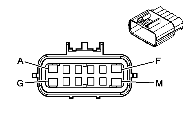
X112 Forward Lamp Harness to Fog Lamp Harness
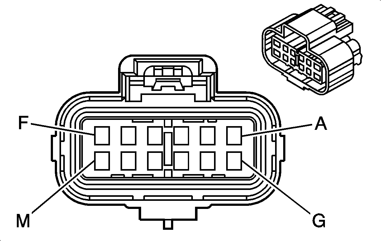
|
|
Connector Part Information
| Connector Part Information
|
Terminal Part Information
| Terminal Part Information
|
Pin | Wire Color | Circuit No. | Function | Pin | Wire Color | Circuit No. | Function |
|---|---|---|---|---|---|---|---|
A | 1.5 BN | 1150 | Ground (T96) | A | 1.5 BN | 1150 | Ground (T96) |
B | 1.5 BN/GY | 5061 | Left Front Fog Lamp Supply Voltage (T96) | B | 1.5 BN/GY | 5061 | Left Front Fog Lamp Supply Voltage (T96) |
C | 1.5 BN | 1050 | Ground (T96) | C | 1.5 BN | 1050 | Ground (T96) |
D | 1.5 BN/GN | 5062 | Right Front Fog Lamp Supply Voltage (T96) | D | 1.5 BN/GN | 5062 | Right Front Fog Lamp Supply Voltage (T96) |
E | 0.5 BU | 636 | Outside Ambient Air Temperature Sensor Signal | E | 0.5 BU | 636 | Outside Ambient Air Temperature Sensor Signal |
F | 0.5 BU/BN | 61 | Low Reference | F | 0.5 BU/BN | 61 | Low Reference |
G | 0.5 BN | 1150 | Ground | G | 0.5 BN | 1150 | Ground |
H | 0.5 BK/WH | 1414 | Left Front Turn Signal Switch Signal | H | 0.5 BK/WH | 1414 | Left Front Turn Signal Switch Signal |
J | 0.5 BN | 1050 | Ground | J | 0.5 BN | 1050 | Ground |
K | 0.5 BK/GN | 1415 | Right Front Turn Signal Switch Signal | K | 0.5 BK/GN | 1415 | Right Front Turn Signal Switch Signal |
L | 0.5 BU | 636 | Outside Ambient Air Temperature Sensor Signal | L | 0.5 BU | 636 | Outside Ambient Air Temperature Sensor Signal |
M | 0.5 BU/BN | 61 | Low Reference | M | 0.5 BU/BN | 61 | Low Reference |
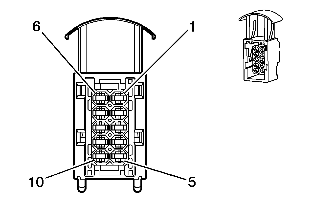
X113 Transmission Harness to Engine and Transmission Harness (MNF)
|

|
Connector Part Information
| Connector Part Information
|
Terminal Part Information
| Terminal Part Information
|
Pin | Wire Color | Circuit No. | Function | Pin | Wire Color | Circuit No. | Function |
|---|---|---|---|---|---|---|---|
1 | 1.5 BK | 539 | Run/Crank Ignition 1 Voltage | 1 | 1.5 BK | 539 | Run/Crank Ignition 1 Voltage |
2 | 0.5 GN | 2500 | High Speed GMLAN Serial Data (+) | 2 | 0.5 BU | 2500 | High Speed GMLAN Serial Data (+) |
3 | 0.5 WH | 2501 | High Speed GMLAN Serial Data (-) | 3 | 0.5 GN | 2501 | High Speed GMLAN Serial Data (-) |
4 | 0.5 GN | 2500 | High Speed GMLAN Serial Data (+) | 4 | 0.5 BU | 2500 | High Speed GMLAN Serial Data (+) |
5 | 0.5 WH | 2501 | High Speed GMLAN Serial Data (-) | 5 | 0.5 GN | 2501 | High Speed GMLAN Serial Data (-) |
6 | 0.75 RD | 3740 | Battery Positive Voltage | 6 | 0.75 RD | 3740 | Battery Positive Voltage |
7 | 0.5 WH | 771 | Transmission Position Switch Bit 1 Signal | 7 | 0.5 WH | 771 | Transmission Position Switch Bit 1 Signal |
8 | 0.5 GN | 772 | Transmission Position Switch Bit 2 Signal | 8 | 0.5 GN/WH | 772 | Transmission Position Switch Bit 2 Signal |
9 | 0.5 GY | 773 | Transmission Position Switch Bit 3 Signal | 9 | 0.5 GY | 773 | Transmission Position Switch Bit 3 Signal |
10 | 0.5 WH/YE | 1371 | Transmission Position Switch Bit 4 Signal | 10 | 0.5 WH/YE | 1371 | Transmission Position Switch Bit 4 Signal |
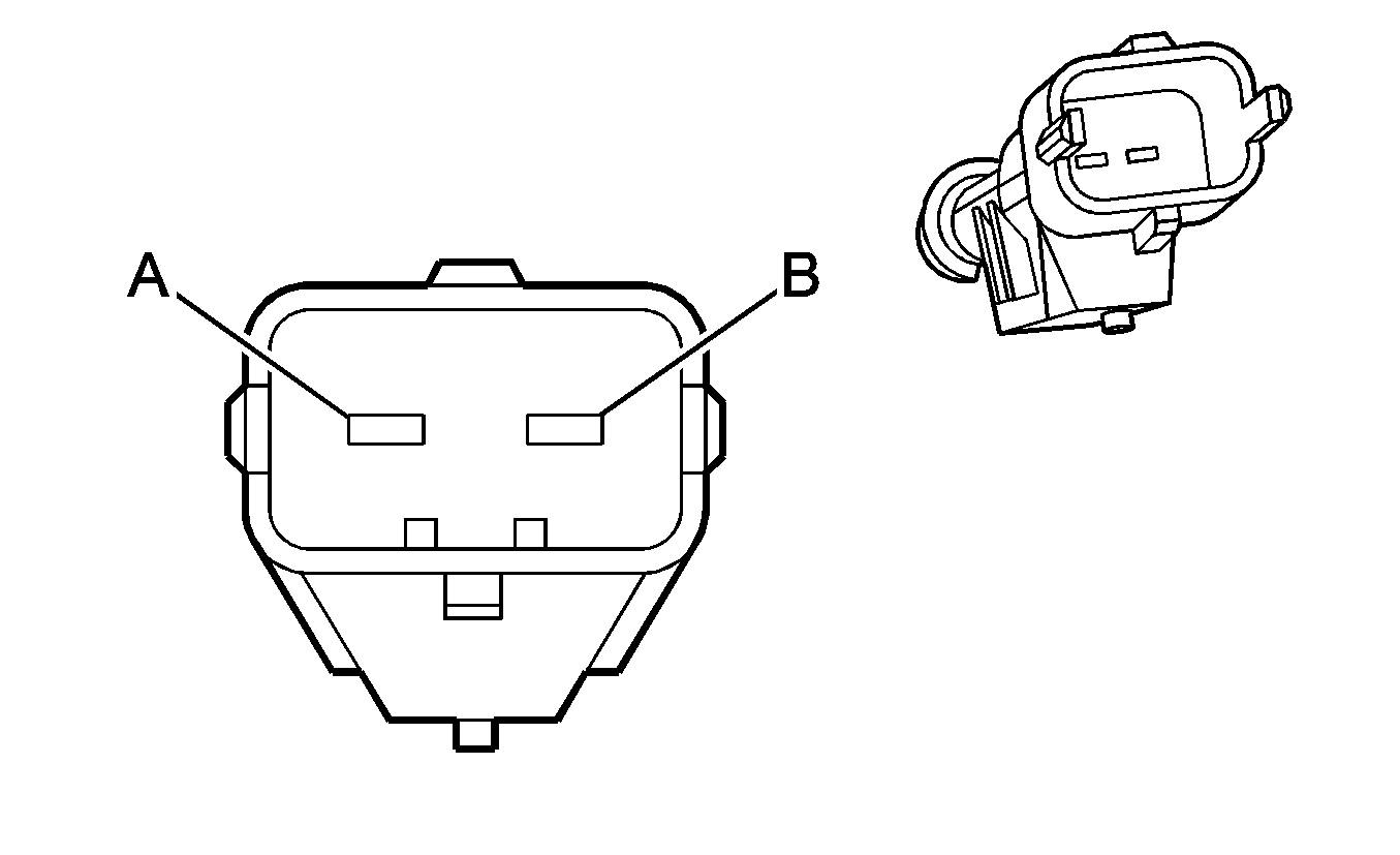
X114 Brake Booster Vacuum Pump Motor Harness to Body Harness

|
|
Connector Part Information
| Connector Part Information
|
Terminal Part Information
| Terminal Part Information
|
Pin | Wire Color | Circuit No. | Function | Pin | Wire Color | Circuit No. | Function |
|---|---|---|---|---|---|---|---|
A | 2.5 BN | 1350 | Ground | A | 2.5 BN | 1350 | Ground |
B | 2.5 BK | 7448 | Brake Booster Pump Supply Voltage | B | 2.5 BK | 7448 | Brake Booster Pump Supply Voltage |
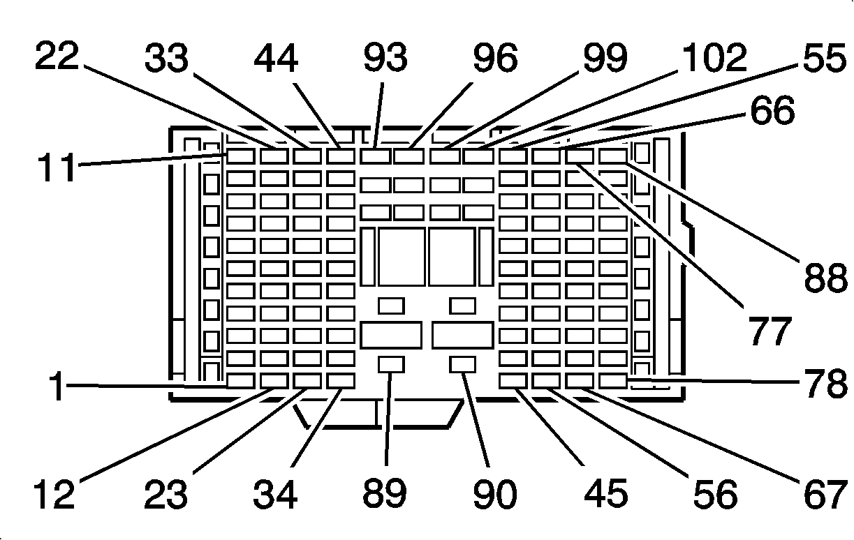
X200 Instrument Panel Harness to Body Harness
|

|
Connector Part Information
| Connector Part Information
|
Terminal Part Information
| Terminal Part Information
|
Pin | Wire Color | Circuit No. | Function | Pin | Wire Color | Circuit No. | Function |
|---|---|---|---|---|---|---|---|
1 | 0.5 BN/RD | 1271 | Low Reference | 1 | 0.5 BN/RD | 1271 | Low Reference |
2 | 0.5 BK/RD | 1164 | 5 Volt Reference 1 | 2 | 0.5 BK/RD | 1164 | 5 Volt Reference 1 |
3 | 0.5 WH/YE | 1161 | Accelerator Pedal Position Signal 1 | 3 | 0.5 WH/YE | 1161 | Accelerator Pedal Position Signal 1 |
4 | 0.5 BN/WH | 1272 | Low Reference | 4 | 0.5 BN/WH | 1272 | Low Reference |
5 | 0.5 BK/YE | 1274 | 5 Volt Reference 2 | 5 | 0.5 BK/YE | 1274 | 5 Volt Reference 2 |
6 | 0.5 WH/GN | 1162 | Accelerator Pedal Position Signal 2 | 6 | 0.5 WH/GN | 1162 | Accelerator Pedal Position Signal 2 |
7 | 0.5 RD | 1542 | Battery Positive Voltage (C60) | 7 | 0.5 RD | 1542 | Battery Positive Voltage |
8 | 0.5 OG/WH | 5018 | Occupant Sensor Serial Data | 8 | 0.5 OG/WH | 5018 | Occupant Sensor Serial Data |
9-11 | -- | -- | Not Used | 9-11 | -- | -- | Not Used |
12 | 0.75 BK | 839 | Run/Crank Ignition 1 Voltage | 12 | 0.75 BK | 839 | Run/Crank Ignition 1 Voltage |
13 | 0.5 BK/YE | 1733 | Inadvertant Power Courtesy Lamp | 13 | 0.5 BK/YE | 1733 | Inadvertant Power Courtesy Lamp |
14-15 | -- | -- | Not Used | 14-15 | -- | -- | Not Used |
16 | 0.5 GY/YE | 1382 | LED Dimming Signal | 16 | 0.5 GY/YE | 1382 | LED Dimming Signal |
17 | 0.75 RD | 1742 | Battery Positive Voltage | 17 | 0.75 RD | 1742 | Battery Positive Voltage |
18 | 0.5 VT | 1935 | CPP Starter Control | 18 | 0.5 VT | 1935 | CPP Starter Control |
19 | 0.5 BU/BN | 1903 | ABS Wheel Speed Sensor Signal Left Front | 19 | 0.5 BU/BN | 1903 | ABS Wheel Speed Sensor Signal Left Front |
20 | 0.5 BK | 1039 | ECM Starter Control | 20 | 0.5 BK | 1039 | ECM Starter Control |
21 | 0.5 BK/BN | 848 | Brake Switch Signal | 21 | 0.5 BK/BN | 848 | Brake Switch Signal |
22 | 0.5 BN/GY | 17 | Stop Lamp Switch Signal | 22 | 0.5 BN/GY | 17 | Stop Lamp Switch Signal |
23 | 0.5 RD/BU | 5293 | Ignition Voltage | 23 | 0.5 RD/BU | 5293 | Ignition Voltage |
24 | 0.5 RD | 302 | Battery Positive Voltage | 24 | 0.5 RD | 302 | Battery Positive Voltage |
25 | 0.5 GN/WH | 377 | Serial Data | 25 | 0.5 GN/WH | 377 | Serial Data |
26 | 0.75 RD | 1442 | Battery Positive Voltage | 26 | 0.75 RD | 1442 | Battery Positive Voltage |
27 | 0.75 BN/BU | 118 | Left Front Speaker Signal (-) | 27 | 0.75 BN/BU | 118 | Left Front Speaker Signal (-) |
28 | 0.75 BU | 201 | Left Front Speaker (+) | 28 | 0.75 BU | 201 | Left Front Speaker (+) |
29 | 0.75 YE | 200 | Right Front Speaker (+) | 29 | 0.75 YE | 200 | Right Front Speaker (+) |
30 | 0.75 BN/YE | 117 | Right Front Speaker Signal (-) | 30 | 0.75 BN/YE | 117 | Right Front Speaker Signal (-) |
31 | 0.75 GN | 199 | Left Rear Speaker (+) | 31 | 0.75 GN | 199 | Left Rear Speaker (+) |
32 | 0.75 BN/GN | 116 | Left Rear Speaker Signal (-) | 32 | 0.75 BN/GN | 116 | Left Rear Speaker Signal (-) |
33-36 | -- | -- | Not Used | 33-36 | -- | -- | Not Used |
37 | 0.5 BK | 1039 | Run/Crank Ignition 1 Voltage | 37 | 0.5 BK | 1039 | Run/Crank Ignition 1 Voltage |
38 | 0.5 GY | 379 | Cruise Control Clutch Pedal Position Switch Signal | 38 | 0.5 GY | 379 | Cruise Control Clutch Pedal Position Switch Signal |
39-40 | -- | -- | Not Used | 39-40 | -- | -- | Not Used |
41 | 0.5 VT/BN | 5968 | Driver Door Lock Status Indicator Signal | 41 | 0.5 VT/BN | 5968 | Driver Door Lock Status Indicator Signal |
42 | -- | -- | Not Used | 42 | -- | -- | Not Used |
43 | 0.75 BK | 3 | Run/Crank Ignition 1 Voltage | 43 | 0.75 BK | 3 | Run/Crank Ignition 1 Voltage |
44 | 0.5 BK | 239 | Run/Crank Ignition 1 Voltage | 44 | 0.5 BK | 239 | Run/Crank Ignition 1 Voltage |
45 | 0.75 RD | 3140 | Battery Positive Voltage | 45 | 0.75 RD | 3140 | Battery Positive Voltage |
46 | 0.75 RD | 1540 | Battery Positive Voltage | 46 | 0.75 RD | 1540 | Battery Positive Voltage |
47 | 0.5 BN/RD | 1134 | Park Brake Switch Signal | 47 | 0.5 BN/RD | 1134 | Park Brake Switch Signal |
48 | 0.5 BN/GY | 1462 | Driver Heated Seat Switch Control (KA1) | 48 | 0.5 BN/GY | 1462 | Driver Heated Seat Switch Control (KA1) |
49 | 0.5 BK/YE | 1505 | Front Passenger Heated Seat Switch Control (KA1) | 49 | 0.5 BK/YE | 1505 | Front Passenger Heated Seat Switch Control (KA1) |
50 | 0.5 GN | 5060 | Low Speed GMLAN Serial Data | 50 | 0.5 GN | 5060 | Low Speed GMLAN Serial Data |
51 | 0.5 GN | 5060 | Low Speed GMLAN Serial Data | 51 | 0.5 GN | 5060 | Low Speed GMLAN Serial Data |
52 | 0.5 WH | 2501 | High Speed GMLAN Serial Data (-) | 52 | 0.5 WH | 2501 | High Speed GMLAN Serial Data (-) |
53 | 0.5 GN | 2500 | High Speed GMLAN Serial Data (+) | 53 | 0.5 GN | 2500 | High Speed GMLAN Serial Data (+) |
54 | -- | -- | Not Used | 54 | -- | -- | Not Used |
55 | 0.5 BN/WH | 28 | Horn Relay Control | 55 | 0.5 BN/WH | 28 | Horn Relay Control |
56-57 | -- | -- | Not Used | 56-57 | -- | -- | Not Used |
58 | 0.5 GN/WH | 2514 | Keypad Signal | 58 | 0.5 GN/WH | 2514 | Keypad Signal |
59 | 0.5 OG/BK | 2518 | 10-Volt Reference | 59 | 0.5 OG/BK | 2518 | 10-Volt Reference |
60 | 0.5 YE/BK | 2516 | Keypad Green LED | 60 | 0.5 YE/BK | 2516 | Keypad Green LED |
61 | 0.5 BN/WH | 2517 | Keypad Red LED | 61 | 0.5 BN/WH | 2517 | Keypad Red LED |
62 | 0.5 WH | 194 | Door Unlock Control | 62 | 0.5 WH | 194 | Door Unlock Control |
63-64 | -- | -- | Not Used | 63-64 | -- | -- | Not Used |
65 | 0.5 BN/YE | 998 | MIL Control | 65 | 0.5 BN/YE | 998 | MIL Control |
66 | 0.35 BK | 5193 | Low Reference | 66 | 0.35 BK | 5193 | Low Reference |
67-76 | -- | -- | Not Used | 67-76 | -- | -- | Not Used |
77 | 0.35 BU/RD | 5191 | Cellular Telephone Microphone Signal | 77 | 0.35 BU/RD | 5191 | Cellular Telephone Microphone Signal |
78-86 | -- | -- | Not Used | 78-86 | -- | -- | Not Used |
87 | 0.75 BN/WH | 115 | Right Rear Speaker Signal (-) | 87 | 0.75 BN/WH | 115 | Right Rear Speaker Signal (-) |
88 | 0.75 WH | 46 | Right Rear Speaker (+) | 88 | 0.75 WH | 46 | Right Rear Speaker (+) |
89 | -- | -- | Not Used | 89 | -- | -- | Not Used |
90 | 4 BK | 1241 | Run Ignition 3 Voltage | 90 | 4 BK | 1241 | Run Ignition 3 Voltage |
91 | 1.5 RD | 502 | Battery Positive Voltage | 91 | 1.5 RD | 502 | Battery Positive Voltage |
92 | -- | -- | Not Used | 92 | -- | -- | Not Used |
93 | 2.5 RD | 3040 | Battery Positive Voltage | 93 | 2.5 RD | 3040 | Battery Positive Voltage |
94-102 | -- | -- | Not Used | 94-102 | -- | -- | Not Used |
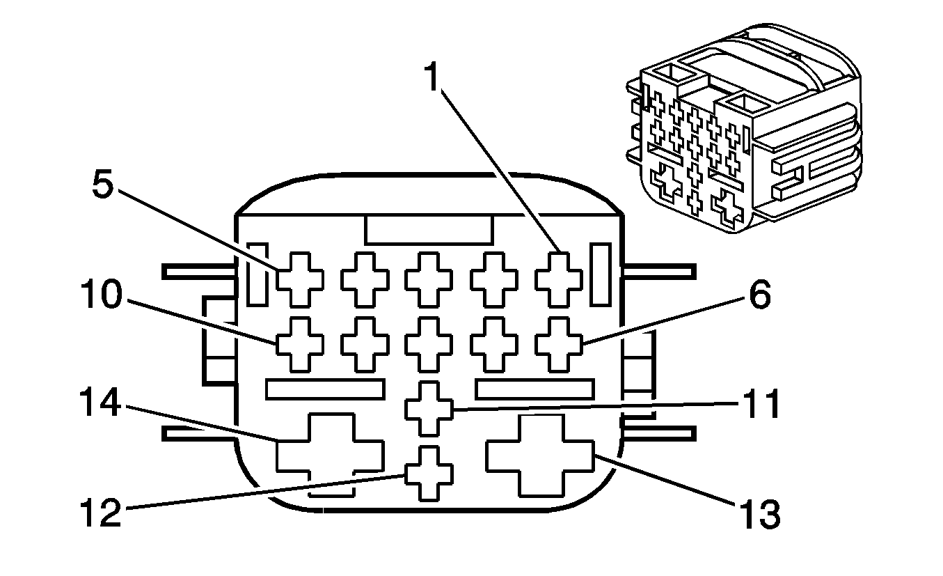
X201 Instrument Panel Harness to HVAC Harness
|
Connector Part Information
| Connector Part Information
|
Terminal Part Information
| Terminal Part Information
|
Pin | Wire Color | Circuit No. | Function | Pin | Wire Color | Circuit No. | Function |
|---|---|---|---|---|---|---|---|
1 | 1 BN | 1650 | Ground | 1 | 1 YE/BK | 1650 | Ground |
2 | 0.5 GY/YE | 1382 | LED Dimming Signal | 2 | 0.5 GN | 1382 | LED Dimming Signal |
3 | -- | -- | Not Used | 3 | -- | -- | Not Used |
4 | 0.5 BK/WH | 292 | Rear Defog Switch Signal | 4 | 0.5 BU | 292 | Rear Defog Switch Signal |
5 | 0.5 BN/WH | 193 | Rear Defog Relay Control | 5 | 0.5 BN/WH | 193 | Rear Defog Relay Control |
6 | 0.5 BK/VT | 66 | A/C Request Signal (C60) | 6 | 0.5 BK/WH | 66 | A/C Request Signal (C60) |
7 | -- | -- | Not Used | 7 | -- | -- | Not Used |
8 | 0.5 RD | 1542 | Battery Positive Voltage (C60) | 8 | 0.5 OG | 1542 | Battery Positive Voltage (C60) |
9 | 0.75 BK | 839 | Run/Crank Ignition 1 Voltage | 9 | 0.75 YE/GN | 839 | Run/Crank Ignition 1 Voltage |
10-12 | -- | -- | Not Used | 10-12 | -- | -- | Not Used |
13 | 4 BK | 1241 | Run Ignition 3 Voltage | 13 | 4 RD | 1241 | Run Ignition 3 Voltage |
14 | 4 BN | 1850 | Ground | 14 | 4 BK | 1850 | Ground |
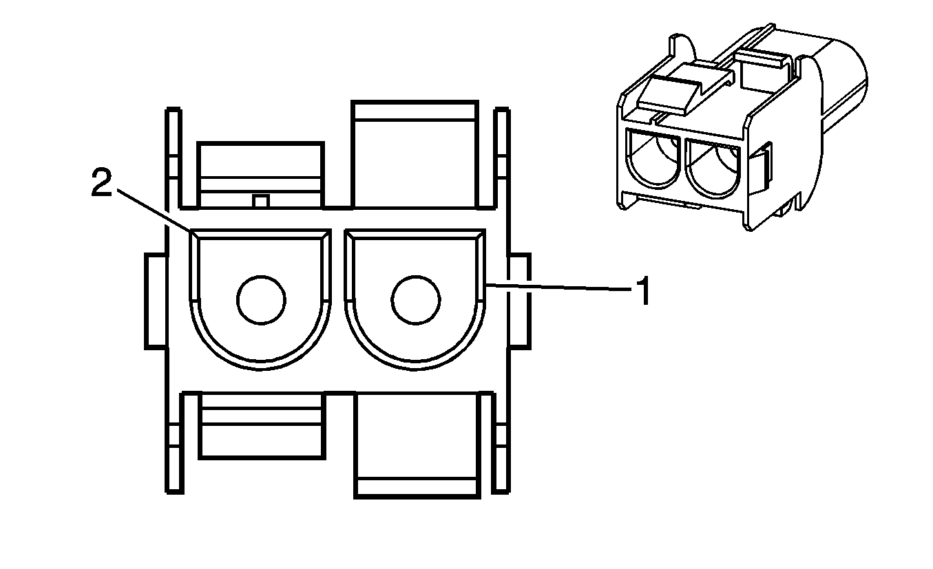
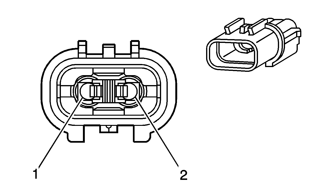
X203 Instrument Panel Harness to Body Harness
|
|
Connector Part Information
| Connector Part Information
|
Terminal Part Information
| Terminal Part Information
|
Pin | Wire Color | Circuit No. | Function | Pin | Wire Color | Circuit No. | Function |
|---|---|---|---|---|---|---|---|
1 | 0.35 COAX | 6794 | GSM Antenna Signal | 1 | 0.35 COAX | 6794 | GSM Antenna Signal |
2 | 0.35 COAX | 5174 | Antenna Navigation Signal | 2 | 0.35 COAX | 5174 | Antenna Navigation Signal |
X204 Instrument Panel Harness to Transmission Harness (MNF)

|

|
Connector Part Information
| Connector Part Information
|
Terminal Part Information
| Terminal Part Information
|
Pin | Wire Color | Circuit No. | Function | Pin | Wire Color | Circuit No. | Function |
|---|---|---|---|---|---|---|---|
1 | 1 BN | 2150 | Ground | 1 | 1 BN | 2150 | Ground (MNF) |
2 | 0.5 BN/GY | 17 | Stop Lamp Switch Signal | 2 | 0.5 BN/GY | 17 | Stop Lamp Switch Signal (MNF) |
3 | 0.5 GY/YE | 1382 | LED Dimming Signal | 3 | 0.5 GY/YE | 1382 | LED Dimming Signal (MNF) |
4-12 | -- | -- | Not Used | 4-12 | -- | -- | Not Used |
X250 Instrument Panel Harness to HVAC Auxiliary Harness

|
Connector Part Information
| Connector Part Information
|
Terminal Part Information
| Terminal Part Information
|
Pin | Wire Color | Circuit No. | Function | Pin | Wire Color | Circuit No. | Function |
|---|---|---|---|---|---|---|---|
1 | BK | 839 | Run/Crank Ignition 1 Voltage | 1 | -- | -- | Option Not Available |
2 | -- | -- | Not Used | 2 | -- | -- | Option Not Available |
3 | GN | 5060 | Low Speed GMLAN Serial Data | 3 | -- | -- | Option Not Available |
4-6 | -- | -- | Not Used | 4-6 | -- | -- | Option Not Available |
7 | BN | 1850 | Ground | 7 | -- | -- | Option Not Available |
8-9 | -- | -- | Not Used | 8-9 | -- | -- | Option Not Available |
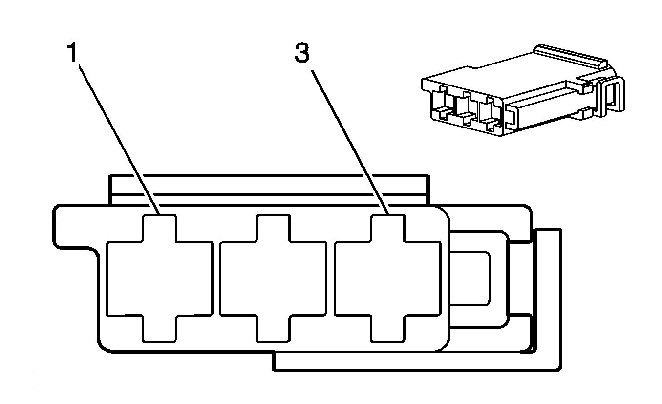
X302 Radio Auxiliary Harness to Instrument Panel Harness
|

|
Connector Part Information
| Connector Part Information
|
Terminal Part Information
| Terminal Part Information
|
Pin | Wire Color | Circuit No. | Function | Pin | Wire Color | Circuit No. | Function |
|---|---|---|---|---|---|---|---|
1 | 0.35 VT/RD | 5841 | Upfitter Provision | 1 | 0.35 VT/RD | 5841 | Right Auxiliary Audio Signal 2 |
2 | 0.35 VT/WH | 5839 | Upfitter Provision | 2 | 0.35 VT/WH | 5839 | Left Auxiliary Audio Signal 2 |
3 | 0.35 BK | 5842 | Upfitter Provision | 3 | 0.35 BK | 5842 | Auxiliary Audio Screen 2 |
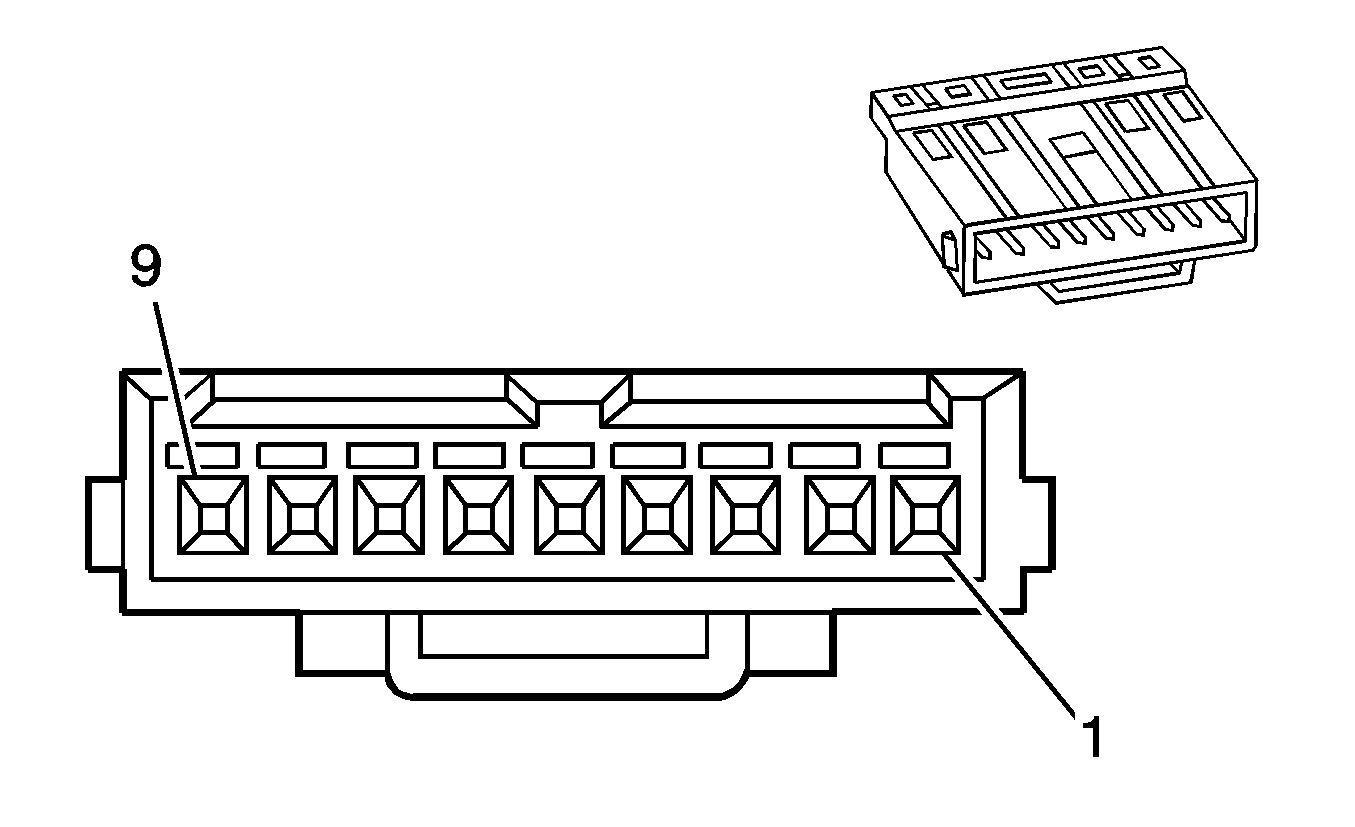
X303 Dome Lamp Harness to Body Harness (- C3U)

|
|
Connector Part Information
| Connector Part Information
|
Terminal Part Information
| Terminal Part Information
|
Pin | Wire Color | Circuit No. | Function | Pin | Wire Color | Circuit No. | Function |
|---|---|---|---|---|---|---|---|
1 | 0.5 FW | 157 | Interior Lamp Control | 1 | 0.5 GY | 157 | Interior Lamp Control |
2 | -- | -- | Not Used | 2 | -- | -- | Not Used |
3 | 0.5 FW | 1732 | Inadvertant Power Courtesy Lamp | 3 | 0.5 RD/BU | 1732 | Inadvertant Power Courtesy Lamp |
4 | 0.5 FW | 1550 | Ground | 4 | 0.5 BN | 1550 | Ground |
5-9 | -- | -- | Not Used | 5-9 | -- | -- | Not Used |
X304 Body Harness to Driver Seat Harness

|

|
Connector Part Information
| Connector Part Information
Connector Part Information
|
Terminal Part Information
| Terminal Part Information
Connector Part Information
Terminal Part Information
Connector Part Information
Terminal Part Information
Connector Part Information
Terminal Part Information
|
Pin | Wire Color | Circuit No. | Function | Pin | Wire Color | Circuit No. | Function |
|---|---|---|---|---|---|---|---|
1 | 0.5 OG/BU | 2137 | Left Front Side Impact Module High Control | 1 | 0.5 BU | 2137 | Left Front Side Impact Module High Control |
2 | 0.5 BU | 2138 | Left Front Side Impact Module Low Control | 2 | 0.5 BN | 2138 | Left Front Side Impact Module Low Control |
3-6 | -- | -- | Not Used | 1-4 | -- | -- | Not Available |
7 | 0.5 BN/GY | 1462 | Heated Seat Switch Signal (KA1) | 1 | 0.5 BN/GY | 1462 | Heated Seat Switch Signal (KA1) |
8 | 1.5 BK | 1041 | Run Ignition 3 Voltage (KA1) | 2 | 1.5 BK | 1041 | Run Ignition 3 Voltage (KA1) |
9 | 1 BN | 2150 | Ground (KA1) | 3 | 1 BN | 2150 | Ground (KA1) |
10 | -- | -- | Not Used (KA1) | 4 | -- | -- | Not Used (KA1) |
11 | 0.5 BN/WH | 238 | Driver Seat Belt Switch Signal | 1 | 0.5 BK | 238 | Driver Seat Belt Switch Signal |
12 | 0.5 VT/BK | 1363 | Low Reference | 2 | 0.5 BK | 1363 | Low Reference |
13-14 | -- | -- | Not Used | 1-2 | -- | -- | Not Used |
15 | 0.5 OG/BN | 2118 | Driver Seat Belt Pretensioner High Control | 3 | 0.5 BU | 2118 | Driver Seat Belt Pretensioner High Control |
16 | 0.5 BN | 2119 | Driver Seat Belt Pretensioner Low Control | 4 | 0.5 BN | 2119 | Driver Seat Belt Pretensioner Low Control |
X305 Body Harness to Passenger Seat Harness

|

|
Connector Part Information
| Connector Part Information
Connector Part Information
|
Terminal Part Information
| Terminal Part Information
Connector Part Information
Terminal Part Information
Connector Part Information
Terminal Part Information
Connector Part Information
Terminal Part Information
Connector Part Information
Terminal Part Information
|
Pin | Wire Color | Circuit No. | Function | Pin | Wire Color | Circuit No. | Function |
|---|---|---|---|---|---|---|---|
1 | 0.5 OG/BK | 2103 | Right Side Impact Module High Control | 1 | 0.5 BU | 2103 | Right Side Impact Module High Control |
2 | 0.5 BK/WH | 2104 | Right Side Impact Module Low Control | 2 | 0.5 BN | 2104 | Right Side Impact Module Low Control |
3-4 | -- | -- | Not Used | 1-2 | -- | -- | Not Used |
5 | 0.5 BU/YE | 5056 | Passenger Seat Position Switch Signal | 3 | 0.5 BK | 5056 | Passenger Seat Position Switch Signal |
6 | 0.5 BU/BK | 1361 | Low Reference | 4 | 0.5 BN | 1361 | Low Reference |
7 | 0.5 BK/YE | 1505 | Passenger Heated Seat Switch Signal (KA1) | 1 | 0.5 BN/GY | 1505 | Passenger Heated Seat Switch Signal (KA1) |
8 | 1.5 BK | 1341 | Run Ignition 3 Voltage (KA1) | 2 | 1.5 BK | 1341 | Run Ignition 3 Voltage (KA1) |
9 | 1 BN | 2150 | Ground (KA!) | 3 | 1 BN | 2150 | Ground (KA1) |
10 | -- | -- | Not Used (KA1) | 4 | -- | -- | Not Used (KA1) |
11 | 0.5 BU | 1362 | Passenger Seat Belt Switch Signal | 1 | 0.5 BK | 1362 | Passenger Seat Belt Switch Signal |
12 | 0.5 BU/BK | 1361 | Passenger Seat Belt Switch Low Reference | 2 | 0.5 BK | 1361 | Passenger Seat Belt Switch Low Reference |
13-14 | -- | -- | Not Used | 1-2 | -- | -- | Not Used |
15 | 0.5 OG/GY | 2116 | Passenger Seat Belt Pretensioner High Control | 3 | 0.5 BU | 2116 | Passenger Seat Belt Pretensioner High Control |
16 | 0.5 BU | 2117 | Passenger Seat Belt Pretensioner Low Control | 4 | 0.5 BN | 2117 | Passenger Seat Belt Pretensioner Low Control |
X306 Transmission Harness to Automatic Transmission Shift Lock Control Jumper Harness (MNF)

|
Connector Part Information
| Connector Part Information
|
Terminal Part Information
| Terminal Part Information
|
Pin | Wire Color | Circuit No. | Function | Pin | Wire Color | Circuit No. | Function |
|---|---|---|---|---|---|---|---|
1 | 0.5 GN | 1078 | Ignition Key/Shifter Interlock Solenoid Lock Signal | 1 | 0.5 GN | 1078 | Ignition Key/Shifter Interlock Solenoid Lock Signal |
2-5 | -- | -- | Not Used | 2-5 | -- | -- | Not Used |
6 | 0.5 BN | 2150 | Ground | 6 | 0.5 BN | 2150 | Ground |
7 | -- | -- | Not Used | 7 | -- | -- | Not Used |
8 | 0.5 BN/GY | 17 | Stop Lamp Switch Signal | 8 | 0.5 YE | 17 | Stop Lamp Switch Signal |
9 | -- | -- | Not Used | 9 | -- | -- | Not Used |
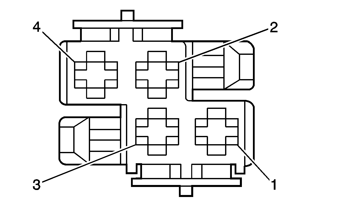
X307 Body harness to Sunroof Harness (C3U)
|

|
Connector Part Information
| Connector Part Information
|
Terminal Part Information
| Terminal Part Information
|
Pin | Wire Color | Circuit No. | Function | Pin | Wire Color | Circuit No. | Function |
|---|---|---|---|---|---|---|---|
1 | 2.5 BN | 1550 | Ground | 1 | 2.5 BK | 1550 | Ground |
2 | 2.5 RD | 140 | Battery Positive Voltage | 2 | 2.5 RD | 140 | Battery Positive Voltage |
3 | 2.5 BN | 1550 | Ground | 3 | 2.5 BK | 1550 | Ground |
4 | 2.5 RD | 142 | Battery Positive Voltage | 4 | 2.5 RD | 142 | Battery Positive Voltage |
X308 Body harness to Sunroof Harness (C3U)

|

|
Connector Part Information
| Connector Part Information
|
Terminal Part Information
| Terminal Part Information
|
Pin | Wire Color | Circuit No. | Function | Pin | Wire Color | Circuit No. | Function |
|---|---|---|---|---|---|---|---|
1 | 0.5 BU/WH | 110 | Sunroof Switch Close Signal | 1 | 0.5 OG | 110 | Sunroof Switch Close Signal |
2 | 0.5 GN/WH | 129 | Sunroof Shade Switch Close Signal | 2 | 0.5 OG | 129 | Sunroof Shade Switch Close Signal |
3 | 0.5 GY | 157 | Interior Lamp Control | 3 | 0.5 YE | 157 | Interior Lamp Control |
4 | 0.5 RD/BU | 1732 | Inadvertant Power Courtesy Lamp | 5 | 0.5 GN | 1732 | Inadvertant Power Courtesy Lamp |
5 | 0.5 BN | 1550 | Ground | 5 | 0.5 WH | 1550 | Ground |
6 | 0.5 GY/YE | 1382 | LED Dimming Signal | 6 | 0.5 RD | 1382 | LED Dimming Signal |
7 | 0.5 BK | 4 | Accessory Voltage | 7 | 0.5 BU | 4 | Accessory Voltage |
8 | -- | -- | Not Used | 8 | 0.5 | GY | Not Used |
9 | -- | -- | Not Used | 9 | -- | -- | Not Used |
X309 Body Harness to Instrument Panel Harness

|

|
Connector Part Information
| Connector Part Information
|
Terminal Part Information
| Terminal Part Information
|
Pin | Wire Color | Circuit No. | Function | Pin | Wire Color | Circuit No. | Function |
|---|---|---|---|---|---|---|---|
1 | -- | -- | Not Used | 1 | -- | -- | Not Used |
2 | 0.35 BK | 5172 | Antenna Radio Signal | 2 | 0.35 BK | 5172 | Antenna Radio Signal |
X400 Fuel Tank Harness to Body Harness

|

|
Connector Part Information
| Connector Part Information
|
Terminal Part Information
| Terminal Part Information
|
Pin | Wire Color | Circuit No. | Function | Pin | Wire Color | Circuit No. | Function |
|---|---|---|---|---|---|---|---|
A | 1.5 RD/BU | 120 | Fuel Pump Supply Voltage | A | 1.5 RD/BU | 120 | Fuel Pump Supply Voltage |
B | 1.5 BN | 2350 | Ground | B | 1.5 BN | 2350 | Ground |
C | 0.5 BN/YE | 251 | Low Reference | C | 0.5 BN/YE | 251 | Low Reference |
D | 0.5 GN/BU | 30 | Fuel Level Sensor Signal | D | 0.5 GN/BU | 30 | Fuel Level Sensor Signal |
E | 0.5 BK/YE | 2709 | 5 Volt Reference 1 | E | 0.5 BK/YE | 2709 | 5 Volt Reference 1 |
F | 0.5 BU/WH | 890 | Fuel Tank Pressure Sensor Signal | F | 0.5 BU/WH | 890 | Fuel Tank Pressure Sensor Signal |
G | 0.5 BK/GN | 2759 | Low Reference | G | 0.5 BK/GN | 2759 | Low Reference |
H | 0.5 BK/BN | 474 | 5 Volt Reference 1 | H | 0.5 BK/BN | 474 | 5 Volt Reference 1 |
J | 0.5 GN/BN | 5266 | Ambient Air Pressure Sensor Signal | J | 0.5 GN/BN | 5266 | Ambient Air Pressure Sensor Signal |
K | 0.5 GN/BK | 6014 | Low Reference | K | 0.5 GN/BK | 6014 | Low Reference |
L | 1 BU | 5372 | Ignition Voltage | L | 1 BU | 5372 | Ignition Voltage |
M | 1 BN | 2350 | EVAP Canister Vent Solenoid Control | M | 1 BN | 2350 | EVAP Canister Vent Solenoid Control |
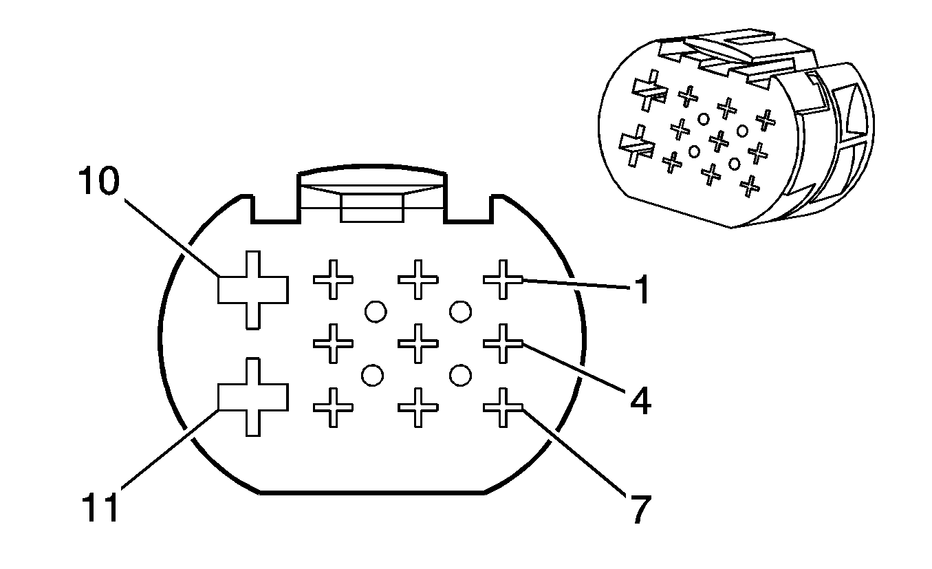
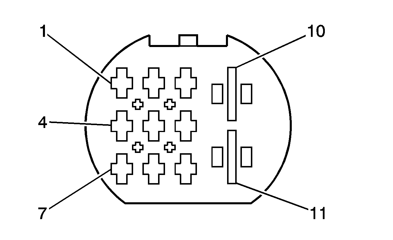
X401 Liftgate Extension Harness to Rear Body Harness
|
|
Connector Part Information
| Connector Part Information
|
Terminal Part Information
| Terminal Part Information
|
Pin | Wire Color | Circuit No. | Function | Pin | Wire Color | Circuit No. | Function |
|---|---|---|---|---|---|---|---|
1 | 0.5 BU/YE | 5797 | Rear Closure Handle Switch Open Signal | 1 | 0.5 BU/YE | 5797 | Rear Closure Handle Switch Open Signal |
2 | 0.75 BN/WH | 5799 | Lift Gate Open/Close Motor Close Control | 2 | 0.75 BN/WH | 5799 | Lift Gate Open/Close Motor Close Control |
3 | 0.5 BK/BU | 1303 | Liftgate Ajar Switch Signal | 3 | 0.5 BK/BU | 1303 | Liftgate Ajar Switch Signal |
4 | -- | -- | Not Used | 4 | -- | -- | Not Used |
5 | 0.5 BK/YE | 820 | CHMSL Supply Voltage | 5 | 0.5 BK/YE | 820 | CHMSL Supply Voltage |
6 | 1.5 BK | 1939 | Run/Crank Ignition 1 Voltage | 6 | 1.5 BK | 1939 | Run/Crank Ignition 1 Voltage |
7 | 1.5 BU | 393 | Rear Window Wiper Motor Control | 7 | 1.5 BU | 393 | Rear Window Wiper Motor Control |
8-9 | -- | -- | Not Used | 8-9 | -- | -- | Not Used |
10 | 4 BN | 2550 | Ground | 10 | 4 BN | 2550 | Ground |
11 | 2.5 BK | 293 | Rear Defog Element Supply Voltage | 11 | 2.5 BK | 293 | Rear Defog Element Supply Voltage |
X402 Rear Facia Harness to Body Rear Harness

|

|
Connector Part Information
| Connector Part Information
|
Terminal Part Information
| Terminal Part Information
|
Pin | Wire Color | Circuit No. | Function | Pin | Wire Color | Circuit No. | Function |
|---|---|---|---|---|---|---|---|
1 | 0.5 GY/GN | 1255 | Side Marker Supply Voltage Signal | 1 | 0.5 GY/GN | 1255 | Side Marker Supply Voltage Signal |
2 | -- | -- | Not Used | 2 | -- | -- | Not Used |
3 | 0.5 BN | 2550 | Ground | 3 | 0.5 BN | 2550 | Ground |
4-5 | -- | -- | Not Used | 4-5 | -- | -- | Not Used |
6 | 0.5 GY/GN | 1255 | Side Marker/License Supply Voltage Signal | 6 | 0.5 GY/GN | 1255 | License Supply Voltage Signal |
X403 Rear Axle ABS Harness to Body Harness

|

|
Connector Part Information
| Connector Part Information
|
Terminal Part Information
| Terminal Part Information
|
Pin | Wire Color | Circuit No. | Function | Pin | Wire Color | Circuit No. | Function |
|---|---|---|---|---|---|---|---|
1 | 0.5 BN/RD | 883 | Low Reference | 1 | 0.5 BN/RD | 883 | Low Reference |
2 | -- | -- | Not Used | 2 | -- | -- | Not Used |
3 | 0.5 BN/BU | 885 | Low Reference | 3 | 0.5 BN/BU | 885 | Low Reference |
4 | 0.5 BU/RD | 882 | Wheel Speed Sensor Signal Right Rear | 4 | 0.5 BU/RD | 882 | Wheel Speed Sensor Signal Right Rear |
5 | -- | -- | Not Used | 5 | -- | -- | Not Used |
6 | 0.5 BU | 884 | Wheel Speed Sensor Signal Left Rear | 6 | 0.5 BU | 884 | Wheel Speed Sensor Signal Left Rear |
X500 Body Harness to Driver Door Harness

|

|
Connector Part Information
| Connector Part Information
|
Terminal Part Information
| Terminal Part Information
|
Pin | Wire Color | Circuit No. | Function | Pin | Wire Color | Circuit No. | Function |
|---|---|---|---|---|---|---|---|
1 | 2.5 RD | 2040 | Battery Positive Voltage | 1 | 2.5 RD | 2040 | Battery Positive Voltage |
2 | 2.5 BN | 1550 | Ground | 2 | 2.5 BN | 1550 | Ground |
3 | 0.75 GY/WH | 7305 | Emergency Door Unlock 2 Signal | 3 | 0.75 GY/WH | 7305 | Emergency Door Unlock 2 Signal |
4 | 0.75 WH | 7304 | Emergency Door Unlock 1 Signal | 4 | 0.75 WH | 7304 | Emergency Door Unlock 1 Signal |
5 | -- | -- | Not Used | 5 | -- | -- | Not Used |
6 | 0.5 WH/GY | 49 | Driver Door Ajar Switch Signal | 6 | 0.5 WH/GY | 49 | Driver Door Ajar Switch Signal |
7 | 0.5 YE/GN | 166 | Power Window Master Switch Right Front Up Signal | 7 | 0.5 YE/GN | 166 | Power Window Master Switch Right Front Up Signal |
8 | 0.5 YE/BN | 167 | Power Window Master Switch Right Front Down Signal | 8 | 0.5 YE/BN | 167 | Power Window Master Switch Right Front Down Signal |
9 | 0.5 BN/BK | 5200 | Power Window Comfort Close Signal | 9 | 0.5 BN/BK | 5200 | Power Window Comfort Close Signal |
10 | 0.75 BU | 201 | Left Front Speaker (+) | 10 | 0.75 BU | 201 | Left Front Speaker (+) |
11 | 0.75 BN/BU | 118 | Left Front Speaker Signal (-) | 11 | 0.75 BN/BU | 118 | Left Front Speaker Signal (-) |
12 | 0.5 BU/BK | 6162 | Outside Right Mirror Vertical Position Control | 12 | 0.5 BU/BK | 6162 | Outside Right Mirror Vertical Position Control |
13 | 0.5 BN | 6163 | Outside Mirror Position Motor Drain Wire | 13 | 0.5 BN | 6163 | Outside Mirror Position Motor Drain Wire |
14 | 0.5 GN/BK | 6161 | Outside Right Mirror Horizontal Position Control | 14 | 0.5 GN/BK | 6161 | Outside Right Mirror Horizontal Position Control |
15 | 0.75 WH/BK | 2267 | Mirror Heating Element Supply Voltage | 15 | 0.75 WH/BK | 2267 | Mirror Heating Element Supply Voltage |
16 | 0.5 VT/GN | 168 | Power Window Master Switch Left Rear Up Signal (5 Door) | 16 | 0.5 VT/GN | 168 | Power Window Master Switch Left Rear Up Signal (5 Door) |
17 | 0.5 VT/BN | 169 | Power Window Master Switch Left Rear Down Signal (5 Door) | 17 | 0.5 VT/BN | 169 | Power Window Master Switch Left Rear Down Signal (5 Door) |
18 | 0.5 BK | 4 | Accessory Voltage | 18 | 0.5 BK | 4 | Accessory Voltage |
19 | 0.5 BU/GN | 170 | Power Window Master Switch Right Rear Up Signal (5 Door) | 19 | 0.5 BU/GN | 170 | Power Window Master Switch Right Rear Up Signal (5 Door) |
20 | 0.5 BU/BN | 171 | Power Window Master Switch Right Rear Down Signal (5 Door) | 20 | 0.5 BU/BN | 171 | Power Window Master Switch Right Rear Down Signal (5 Door) |
21 | 0.5 WH/BU | 1307 | Power Window Master Switch Lockout Signal (5 Door) | 21 | 0.5 WH/BU | 1307 | Power Window Master Switch Lockout Signal (5 Door) |
22-34 | -- | -- | Not Used | 22-34 | -- | -- | Not Used |
X600 Body Harness to Passenger Door Harness

|

|
Connector Part Information
| Connector Part Information
|
Terminal Part Information
| Terminal Part Information
|
Pin | Wire Color | Circuit No. | Function | Pin | Wire Color | Circuit No. | Function |
|---|---|---|---|---|---|---|---|
1 | 2.5 RD | 2140 | Battery Positive Voltage | 1 | 2.5 RD | 2140 | Battery Positive Voltage |
2 | 2.5 BN | 2050 | Ground | 2 | 2.5 BN | 2050 | Ground |
3 | 0.75 GY/WH | 7305 | Emergency Door Unlock 2 Signal | 3 | 0.75 GY/WH | 7305 | Emergency Door Unlock 2 Signal |
4 | 0.75 WH | 7304 | Emergency Door Unlock 1 Signal | 4 | 0.75 WH | 7304 | Emergency Door Unlock 1 Signal |
5 | -- | -- | Not Used | 5 | -- | -- | Not Used |
6 | 0.5 GY | 746 | Right Front Door Ajar Switch Signal | 6 | 0.5 GY | 746 | Right Front Door Ajar Switch Signal |
7 | 0.5 YE/GN | 166 | Power Window Master Switch Right Front Up Signal | 7 | 0.5 YE/GN | 166 | Power Window Master Switch Right Front Up Signal |
8 | 0.5 YE/BN | 167 | Power Window Master Switch Right Front Down Signal | 8 | 0.5 YE/BN | 167 | Power Window Master Switch Right Front Down Signal |
9 | 0.5 BN/BK | 5200 | Power Window Comfort Close Signal | 9 | 0.5 BN/BK | 5200 | Power Window Comfort Close Signal |
10 | 0.75 YE | 200 | Right Front Speaker (+) | 10 | 0.75 YE | 200 | Right Front Speaker (+) |
11 | 0.75 BN/YE | 117 | Right Front Speaker Signal (-) | 11 | 0.75 BN/YE | 117 | Right Front Speaker Signal (-) |
12 | 0.5 BU/BK | 6162 | Outside Right Mirror Vertical Position Control | 12 | 0.5 BU/BK | 6162 | Outside Right Mirror Vertical Position Control |
13 | 0.5 BN | 6163 | Outside Mirror Position Motor Drain Wire | 13 | 0.5 BN | 6163 | Outside Mirror Position Motor Drain Wire |
14 | 0.5 GN/BK | 6161 | Outside Right Mirror Horizontal Position Control | 14 | 0.5 GN/BK | 6161 | Outside Right Mirror Horizontal Position Control |
15 | 0.75 WH/BK | 2267 | Mirror Heating Element Supply Voltage | 15 | 0.75 WH/BK | 2267 | Mirror Heating Element Supply Voltage |
16-17 | -- | -- | Not Used | 16-17 | -- | -- | Not Used |
18 | 0.5 BK | 4 | Accessory Voltage | 18 | 0.5 BK | 4 | Accessory Voltage |
19-34 | -- | -- | Not Used | 19-34 | -- | -- | Not Used |
X700 Body Harness to Left Rear Door Harness (5 Door)

|

|
Connector Part Information
| Connector Part Information
|
Terminal Part Information
| Terminal Part Information
|
Pin | Wire Color | Circuit No. | Function | Pin | Wire Color | Circuit No. | Function |
|---|---|---|---|---|---|---|---|
1 | 2.5 RD | 2240 | Battery Positive Voltage | 1 | 2.5 RD | 2240 | Battery Positive Voltage |
2 | 2.5 BN | 2350 | Ground | 2 | 2.5 BN | 2350 | Ground |
3 | 0.75 GY/WH | 7305 | Emergency Door Unlock 2 Signal | 3 | 0.75 GY/WH | 7305 | Emergency Door Unlock 2 Signal |
4 | 0.75 WH | 7304 | Emergency Door Unlock 1 Signal | 4 | 0.75 WH | 7304 | Emergency Door Unlock 1 Signal |
5 | -- | -- | Not Used | 5 | -- | -- | Not Used |
6 | 0.5 GY | 747 | Left Rear Door Ajar Switch Signal | 6 | 0.5 GY | 747 | Left Rear Door Ajar Switch Signal |
6 | 0.5 GY | 747 | Left Rear Door Ajar Switch Signal | 6 | 0.5 GY | 747 | Left Rear Door Ajar Switch Signal |
7 | -- | -- | Not Used | 12 | -- | -- | Not Used |
8 | -- | -- | Not Used | 11 | -- | -- | Not Used |
9 | -- | -- | Not Used | 10 | -- | -- | Not Used |
10 | 0.5 WH/BU | 1307 | Power Window Master Switch Lockout Signal | 9 | 0.5 WH/BU | 1307 | Power Window Master Switch Lockout Signal |
11 | 0.5 VT/GN | 168 | Power Window Master Switch Left Rear Up Signal | 8 | 0.5 VT/GN | 168 | Power Window Master Switch Left Rear Up Signal |
12 | 0.5 VT/BN | 169 | Power Window Master Switch Left Rear Down Signal | 7 | 0.5 VT/BN | 169 | Power Window Master Switch Left Rear Down Signal |
13 | -- | -- | Not Used | 19 | -- | -- | Not Used |
14 | -- | -- | Not Used | 14 | -- | -- | Not Used |
15 | -- | -- | Not Used | 17 | -- | -- | Not Used |
16 | 0.75 GN | 199 | Left Rear Speaker (+) | 16 | 0.75 GN | 199 | Left Rear Speaker (+) |
17 | 0.75 BN/GN | 116 | Left Rear Speaker Signal (-) | 15 | 0.75 BN/GN | 116 | Left Rear Speaker Signal (-) |
18 | -- | -- | Not Used | 18 | -- | -- | Not Used |
19 | 0.5 BN/BK | 5200 | Power Window Comfort Close Signal | 13 | 0.5 BN/BK | 5200 | Power Window Comfort Close Signal |
X800 Body Harness to Right Rear Door Harness (5 Door)

|

|
Connector Part Information
| Connector Part Information
|
Terminal Part Information
| Terminal Part Information
|
Pin | Wire Color | Circuit No. | Function | Pin | Wire Color | Circuit No. | Function |
|---|---|---|---|---|---|---|---|
1 | 2.5 RD | 2340 | Battery Positive Voltage | 1 | 2.5 RD | 2340 | Battery Positive Voltage |
2 | 2.5 BN | 2050 | Ground | 2 | 2.5 BN | 2350 | Ground |
3 | 0.75 GY/WH | 7305 | Emergency Door Unlock 2 Signal | 3 | 0.75 GY/WH | 7305 | Emergency Door Unlock 2 Signal |
4 | 0.75 WH | 7304 | Emergency Door Unlock 1 Signal | 4 | 0.75 WH | 7304 | Emergency Door Unlock 1 Signal |
5 | -- | -- | Not Used | 5 | -- | -- | Not Used |
6 | 0.5 GY | 748 | Right Rear Door Ajar Switch Signal | 6 | 0.5 GY | 748 | Right Rear Door Ajar Switch Signal |
7 | -- | -- | Not Used | 12 | -- | -- | Not Used |
8 | -- | -- | Not Used | 11 | -- | -- | Not Used |
9 | -- | -- | Not Used | 10 | -- | -- | Not Used |
10 | 0.5 WH/BU | 1307 | Power Window Master Switch Lockout Signal | 9 | 0.5 WH/BU | 1307 | Power Window Master Switch Lockout Signal |
11 | 0.5 BU/GN | 170 | Power Window Master Switch Right Rear Up Signal | 8 | 0.5 VT/GN | 168 | Power Window Master Switch Right Rear Up Signal |
12 | 0.5 BU/BN | 171 | Power Window Master Switch Right Rear Down Signal | 7 | 0.5 VT/BN | 169 | Power Window Master Switch Right Rear Down Signal |
13 | -- | -- | Not Used | 19 | -- | -- | Not Used |
14 | -- | -- | Not Used | 14 | -- | -- | Not Used |
15 | -- | -- | Not Used | 17 | -- | -- | Not Used |
16 | 0.75 WH | 46 | Right Rear Speaker (+) | 16 | 0.75 GN | 199 | Right Rear Speaker (+) |
17 | 0.75 BN/WH | 115 | Right Rear Speaker Signal (-) | 15 | 0.75 BN/WH | 115 | Right Rear Speaker Signal (-) |
18 | -- | -- | Not Used | 18 | -- | -- | Not Used |
19 | 0.5 BN/BK | 5200 | Power Window Comfort Close Signal | 13 | 0.5 BN/BK | 5200 | Power Window Comfort Close Signal |
X901 Liftgate Extension Harness to Liftgate Harness

|

|
Connector Part Information
| Connector Part Information
|
Terminal Part Information
| Terminal Part Information
|
Pin | Wire Color | Circuit No. | Function | Pin | Wire Color | Circuit No. | Function |
|---|---|---|---|---|---|---|---|
1 | 0.5 BU/YE | 5797 | Rear Closure Handle Switch Open Signal | 1 | 0.5 BU/YE | 5797 | Rear Closure Handle Switch Open Signal |
2 | 0.75 BN/WH | 5799 | Lift Gate Open/Close Motor Close Control | 2 | 0.75 BN/WH | 5799 | Lift Gate Open/Close Motor Close Control |
3 | 0.5 BK/BU | 1303 | Liftgate Ajar Switch Signal | 3 | 0.5 BK/BU | 1303 | Liftgate Ajar Switch Signal |
4 | -- | -- | Not Used | 4 | -- | -- | Not Used |
5 | 0.5 BK/YE | 820 | CHMSL Supply Voltage | 5 | 0.5 BK/YE | 820 | CHMSL Supply Voltage |
6 | 1.5 BK | 1939 | Run/Crank Ignition 1 Voltage | 6 | 1.5 BK | 1939 | Run/Crank Ignition 1 Voltage |
7 | 1.5 BU | 393 | Rear Window Wiper Motor Control | 7 | 1.5 BU | 393 | Rear Window Wiper Motor Control |
8-9 | -- | -- | Not Used | 8-9 | -- | -- | Not Used |
10 | 4 BN | 2550 | Ground | 10 | 4 BN | 2550 | Ground |
11 | 2.5 BK | 293 | Rear Defog Element Supply Voltage | 11 | 2.5 BK | 293 | Rear Defog Element Supply Voltage |
