DTC P1574 2.2L
Circuit Description
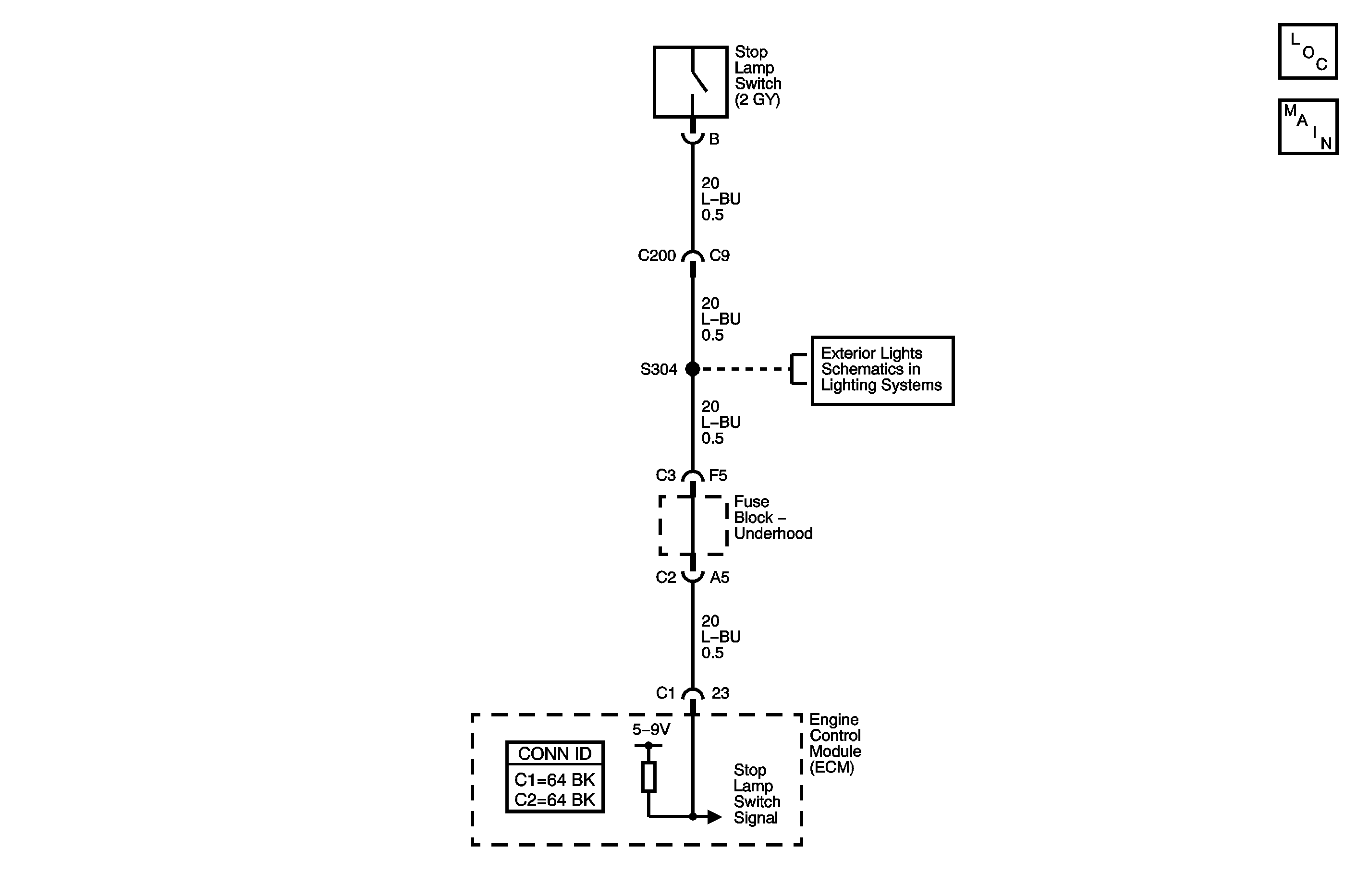
This diagnostic test functions on the assumption that a sudden decrease in vehicle speed is caused by a brake pedal application. When the engine control module (ECM) detects that there is a 4.2 km/h (2.6 mph) or greater decrease in vehicle speed within 0.25 second and a transition of the cruise/brake switch without a transition of the stop lamp switch, the ECM sets DTC P1574.
DTC Descriptor
This diagnostic procedure supports the following DTC:
DTC P1574 Stop Lamp Switch Circuit
Conditions for Running the DTC
| • | DTCs P0502, P0503, P0719, and P0724 are not set. |
| • | The engine speed is greater than 700 RPM. |
| • | The traction control system or the antilock brake system are not active and have not failed. |
| • | The vehicle speed is greater than 48 km/h (30 mph) in order to enable the diagnostic. |
| • | The diagnostic will disable when the wheel speed is less than 16 km/h (10 mph). |
Conditions for Setting the DTC
| • | The vehicle speed decreases by at least 4.2 km/h (2.6 mph) within 0.25 second. |
| • | The ECM detects a cruise/brake transition. |
| • | The ECM does not detect a stop lamp switch transition. |
Action Taken When the DTC Sets
| • | The ECM sets the stop lamp switch status to released. |
| • | The ECM disables the operation of the cruise control system. |
Conditions for Clearing the DTC
| • | A history DTC will clear after 40 malfunction-free warm-up cycles. |
| • | The ECM receives a clear code command from the scan tool. |
Diagnostic Aids
In order to avoid a misdiagnosis, perform the following:
| • | Inspect for proper operation of the stop lamps. Refer to Exterior Lighting Systems Description and Operation . |
| • | Inspect for proper adjustment of the stop lamps. Refer to Stop Lamp Switch Adjustment . |
| • | Inspect for proper adjustment of the cruise control release switch. Refer to Cruise Release Switch Adjustment . |
| • | For an intermittent condition, refer to Testing for Intermittent Conditions and Poor Connections . |
Step | Action | Yes | No |
|---|---|---|---|
Schematic Reference : Cruise Control Schematics Connector End View Reference: Cruise Control Connector End Views or Lighting Systems Connector End Views | |||
1 | Did you perform the Diagnostic System Check - Vehicle? | Go to Step 2 | |
2 |
Does the Brake Pedal Switch parameter display Released? | Go to Step 3 | Go to Diagnostic Aids |
3 | Do the stop lamps operate properly? | Go to Step 4 | Go to Stop Lamps Inoperative |
4 | Test the stop lamp switch signal circuit for an open or for a high resistance. Refer to Circuit Testing and Wiring Repairs . Did you complete the repair? | Go to Step 7 | Go to Step 5 |
5 | Inspect for poor connections at the harness connector of the engine control module (ECM). Refer to Testing for Intermittent Conditions and Poor Connections and Connector Repairs . Did you find and correct the condition? | Go to Step 7 | Go to Step 6 |
6 | Replace the ECM. Refer to Control Module References for replacement, setup, and programming. Did you complete the replacement? | Go to Step 7 | -- |
7 |
Does the DTC reset? | Go to Step 2 | System OK |
DTC P1574 3.5L

Circuit Description
This diagnostic test functions on the assumption that a sudden decrease in vehicle speed is caused by a brake pedal application. When the powertrain control module (PCM) detects that there is a 4.2 km/h (2.6 mph) or greater decrease in vehicle speed within 0.25 second and a transition of the cruise/brake switch without a transition of the stop lamp switch, the PCM sets DTC P1574.
DTC Descriptor
This diagnostic procedure supports the following DTC:
DTC P1574 Stop Lamp Switch Circuit
Conditions for Running the DTC
| • | DTCs P0502, P0503, P0719, and P0724 are not set. |
| • | The engine speed is greater than 700 RPM. |
| • | The traction control system or the antilock brake system are not active and have not failed. |
| • | The vehicle speed is greater than 48 km/h (30 mph) in order to enable the diagnostic. |
| • | The diagnostic will disable when the wheel speed is less than 16 km/h (10 mph). |
Conditions for Setting the DTC
| • | The vehicle speed decreases by at least 4.2 km/h (2.6 mph) within 0.25 second. |
| • | The PCM detects a cruise/brake transition. |
| • | The PCM does not detect a stop lamp switch transition. |
Action Taken When the DTC Sets
| • | The PCM sets the stop lamp switch status to released. |
| • | The PCM disables the operation of the cruise control system. |
| • | The Service Vehicle Soon (SVS) light may be illuminated. |
Conditions for Clearing the DTC
| • | A history DTC will clear after 40 malfunction-free warm-up cycles. |
| • | The PCM receives a clear code command from the scan tool. |
Diagnostic Aids
In order to avoid a misdiagnosis, perform the following:
| • | Inspect for proper operation of the stop lamps. Refer to Exterior Lighting Systems Description and Operation . |
| • | Inspect for proper adjustment of the stop lamps. Refer to Stop Lamp Switch Adjustment . |
| • | Inspect for proper adjustment of the cruise control release switch. Refer to Cruise Release Switch Adjustment . |
| • | For an intermittent condition, refer to Testing for Intermittent Conditions and Poor Connections . |
Step | Action | Yes | No |
|---|---|---|---|
Schematic Reference : Cruise Control Schematics Connector End View Reference: Cruise Control Connector End Views or Lighting Systems Connector End Views | |||
1 | Did you perform the Diagnostic System Check - Vehicle? | Go to Step 2 | |
2 |
Does the Brake Pedal Switch parameter display Released? | Go to Step 3 | Go to Diagnostic Aids |
3 | Do the stop lamps operate properly? | Go to Step 4 | Go to Stop Lamps Inoperative |
4 | Test the stop lamp switch signal circuit for an open or for a high resistance. Refer to Circuit Testing and Wiring Repairs . Did you complete the repair? | Go to Step 7 | Go to Step 5 |
5 | Inspect for poor connections at the harness connector of the PCM. Refer to Testing for Intermittent Conditions and Poor Connections and Connector Repairs . Did you find and correct the condition? | Go to Step 7 | Go to Step 6 |
6 | Replace the PCM. Refer to Control Module References for replacement, setup, and programming. Did you complete the replacement? | Go to Step 7 | -- |
7 |
Does the DTC reset? | Go to Step 2 | System OK |
