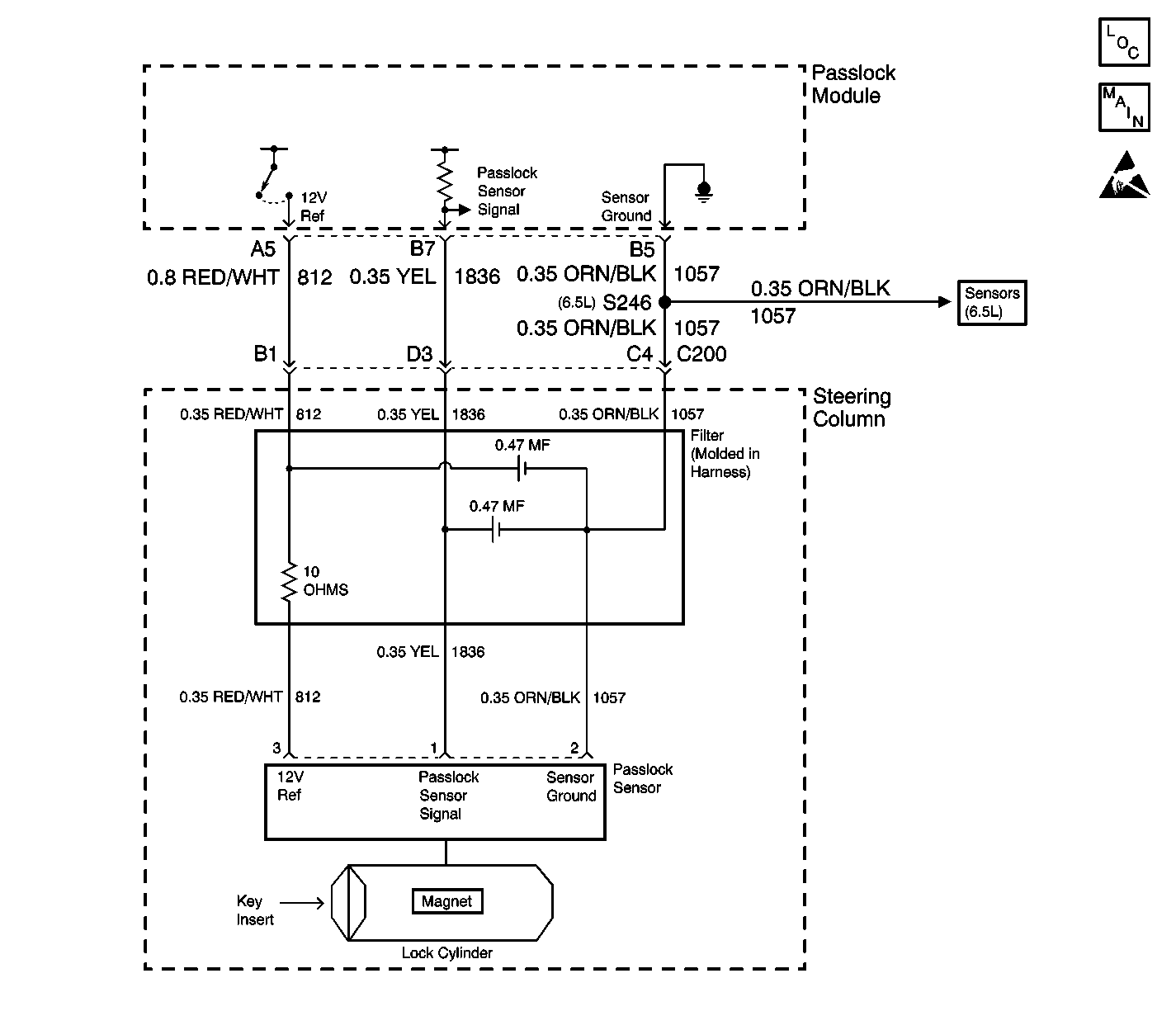
Circuit Description
The Passlock™ Module will read an analog voltage from the Passlock™ Sensor. Based on an internal reference, the Passlock™ Module will determine if the measured voltage is open, shorted to ground, a valid code, or a tamper code. In this case, the Passlock™ Module is reading a tamper code.
Conditions for Setting the DTC
| • | The Passlock™ Module will inspect for a tamper code when the ignition is rotated from ON to crank. |
| • | The Passlock™ Module is reading a tamper code form the Passlock™ Sensor for longer than 1.0 second. |
Action Taken When the DTC Sets
| • | The vehicle will not run. The security telltale will be flashing. |
| • | The Passlock™ state is Tamper. |
Conditions for Clearing the DTC
| • | The DTC will clear after an ignition cycle has occurred without the fault. |
| • | Passlock™ Module history codes will be cleared after 100 ignition cycles with no current codes active. |
| • | Using a scan tool. |
Diagnostic Aids
| • | Prior to replacing a Passlock™ Module, insure all the diagnostics have been completed, Refer to Diagnostic Trouble Code (DTC) List/Type for troubleshooting priority. |
| • | Perform a visual inspection of the wiring and the connectors. |
| • | Inspect the Passlock™ Sensor harness for an intermittent or poor connections (including the in-line connector). Refer to Testing for Intermittent Conditions and Poor Connections . |
Test Description
The numbers below refer to the numbers on the diagnostic table.
-
This step test if DTC B3033 is intermittent.
-
This test inspects for a mechanical condition.
-
This step will determine if the condition is in the Passlock™ Module or the Passlock™ Sensor.
Step | Action | Value(s) | Yes | No | ||||||||||||
|---|---|---|---|---|---|---|---|---|---|---|---|---|---|---|---|---|
1 | Did you perform the VTD Diagnostic System Check? | -- | Go to Step 2 | |||||||||||||
Did DTC B3033 set? | -- | Go to Step 3 | Go to Testing for Intermittent Conditions and Poor Connections in Wiring Systems | |||||||||||||
Inspect the Ignition Lock Cylinder mechanical assembly. Is there binding or has the cylinder magnet, located at the side of the Lock Cylinder, been damaged? | -- | Go to Step 7 | Go to Step 5 | |||||||||||||
4 | Replace the Passlock™ Sensor in the electronic column lock module assembly using the appropriate procedure from the following list:
Is the repair complete? | -- | Go to Step 8 | -- | ||||||||||||
Is the voltage within the specified range? | 4.9-5.0 volts | Go to Step 4 | Go to Step 6 | |||||||||||||
6 | Replace the Passlock™ Module. Refer to Theft Deterrent Module Replacement . Is the repair complete? | -- | Go to Step 8 | -- | ||||||||||||
7 | Replace the Ignition Lock Cylinder, refer to Ignition Lock Cylinder Replacement - On Vehicle in Steering Wheel and Column. Is the repair complete? | -- | -- | |||||||||||||
8 |
Is the repair complete? | -- | -- |
