Removal Procedure
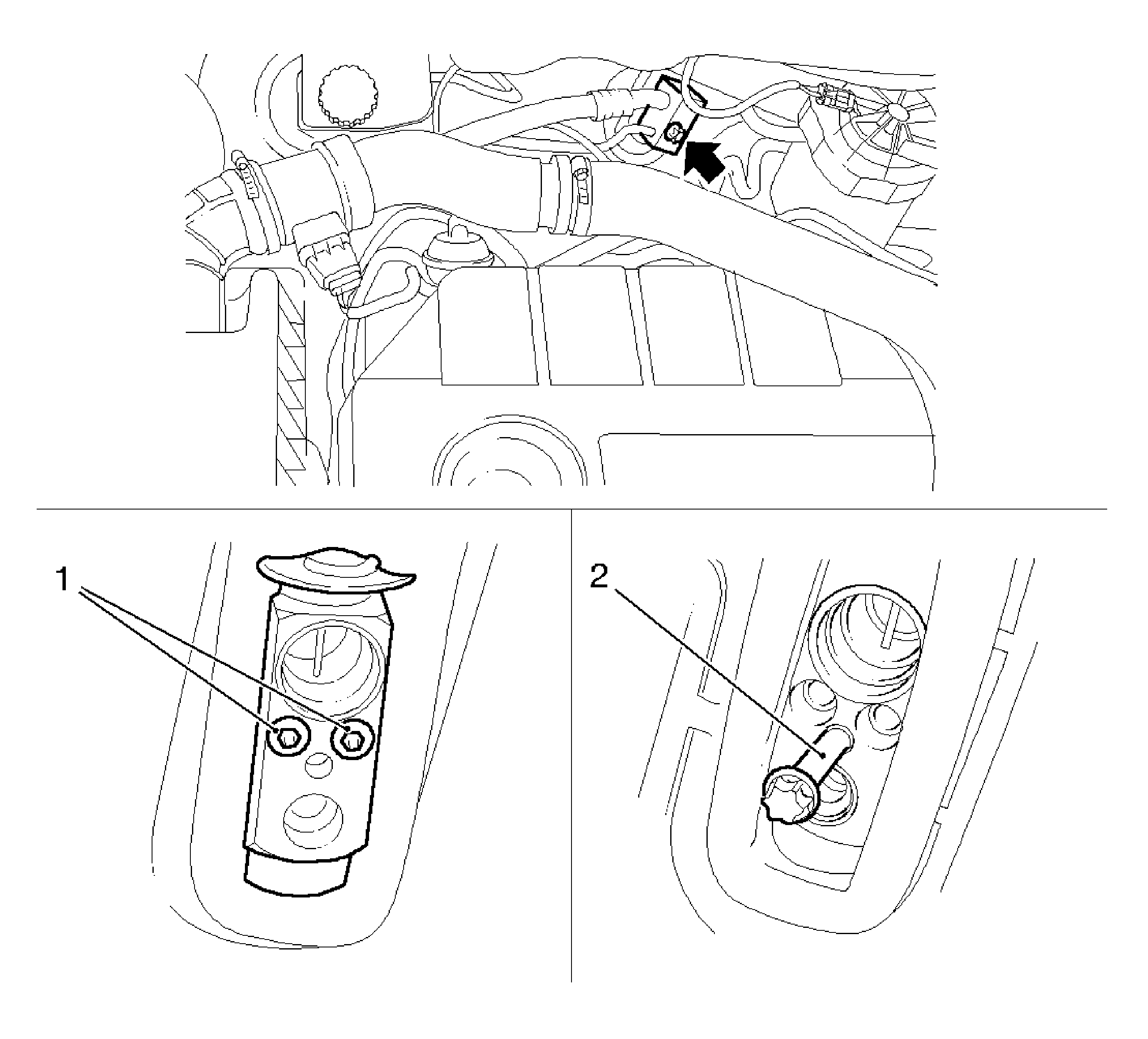
- For vehicles equipped with air conditioning (A/C) remove the block connector and the refrigerant lines from expansion valve.
| 1.2. | Detach the refrigerant lines. |
Important: If installation is postponed, close off lines and connections.
- Remove the thermostatically controlled expansion valve (TXV) (1).
Insert the bolt, block connector refrigerant line in the expansion valve (2) and remove the expansion valve.
- For vehicles equipped with A/C, remove the expansion valve retaining plate.
Important: Depressurize the cooling system by opening and re-closing closure cap on coolant compensation tank.
- Drain the coolant.
Collect the coolant in a drip pan.

- Remove the condensation drain hose (1).
Remove the 2 bolts.
Important: Mark the coolant hose (3) and connection (2) before removal to avoid confusion when refitting.
- Disconnect the coolant hose.
| 6.1. | Detach the 2 coolant hoses. |
| 6.2. | Release the 2 quick-release fittings. |
- Remove the instrument panel (I/P) trim panel. Refer to
Instrument Panel Trim Panel Replacement
.
- Remove the inflatable restraint I/P module. Refer to
Inflatable Restraint Instrument Panel Module Replacement
.
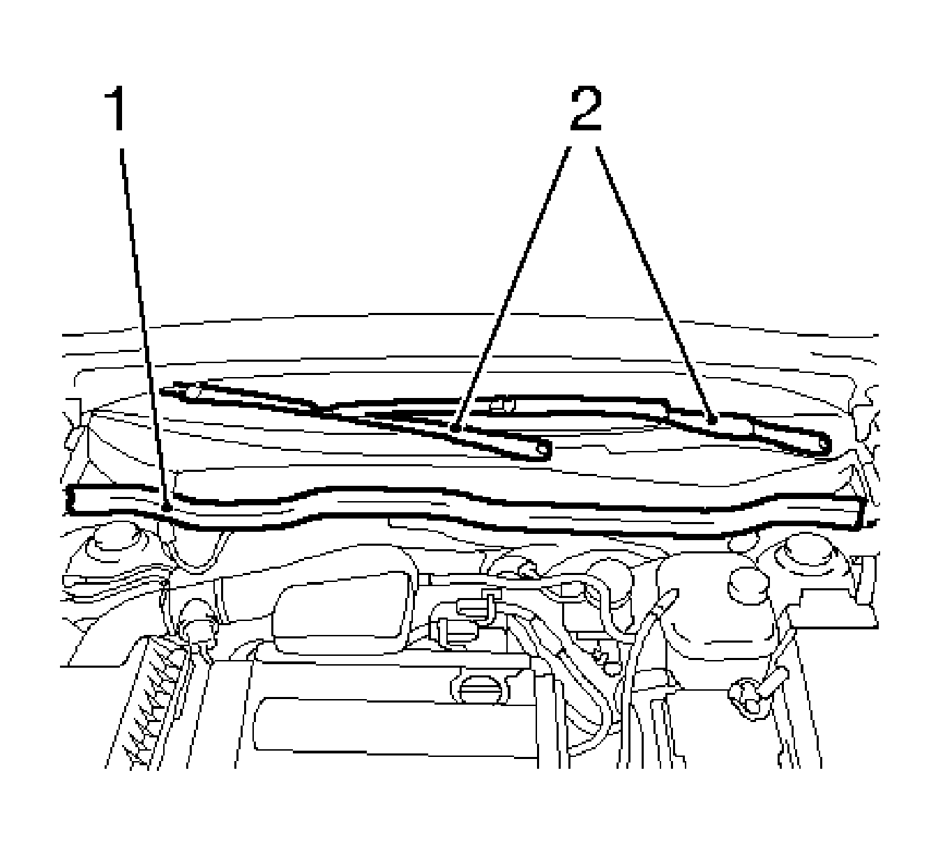
- Remove the air inlet screen (1).
- Remove the windshield wiper arms (2).
| 10.1. | Remove the 2 covers. |
| 10.3. | Remove the 2 washers. |
| 10.4. | Detach the 2 wiper arms from the shaft. |
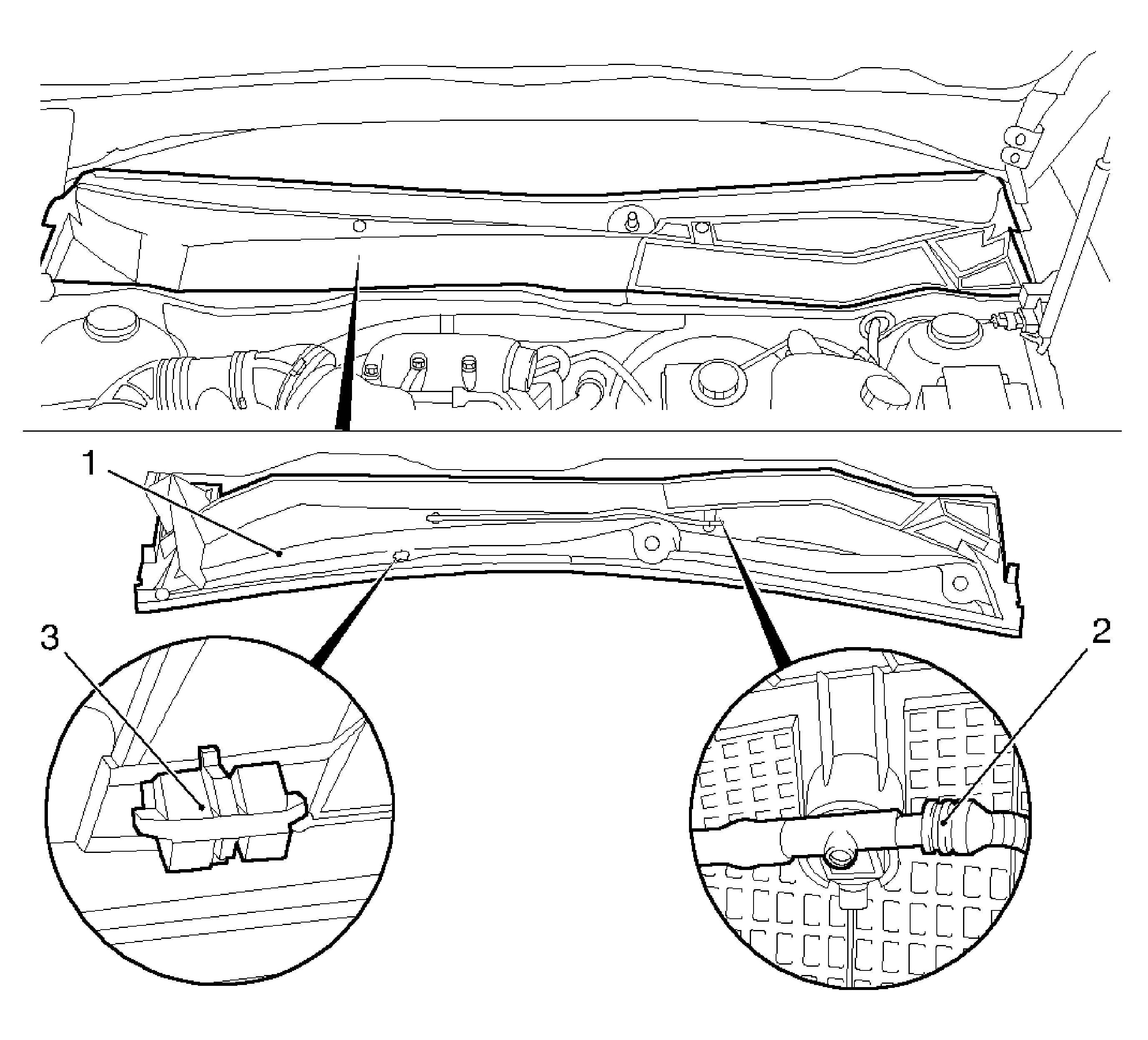
- Remove the air inlet screen (1).
| 11.1. | Lift the air inlet screen trim in dash area. |
| | Important: Carefully release the clips from the dash bracket from inside outward.
|
| 11.2. | Release the 5 clips (3). |
| 11.3. | Remove the hose (2) from the windshield washer system. |
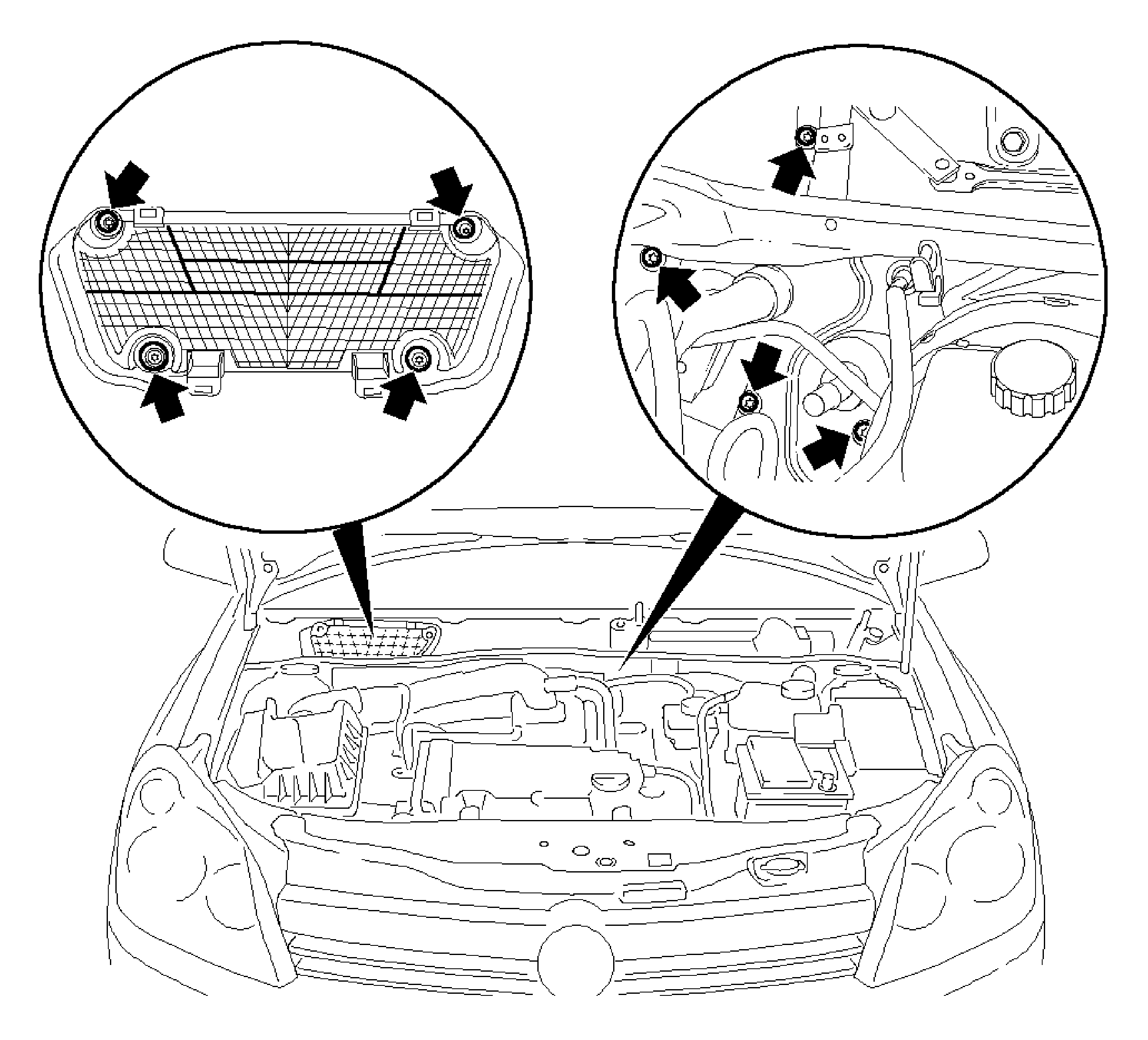
- Remove the air distributor housing from dash outside.
Remove the 8 bolts.
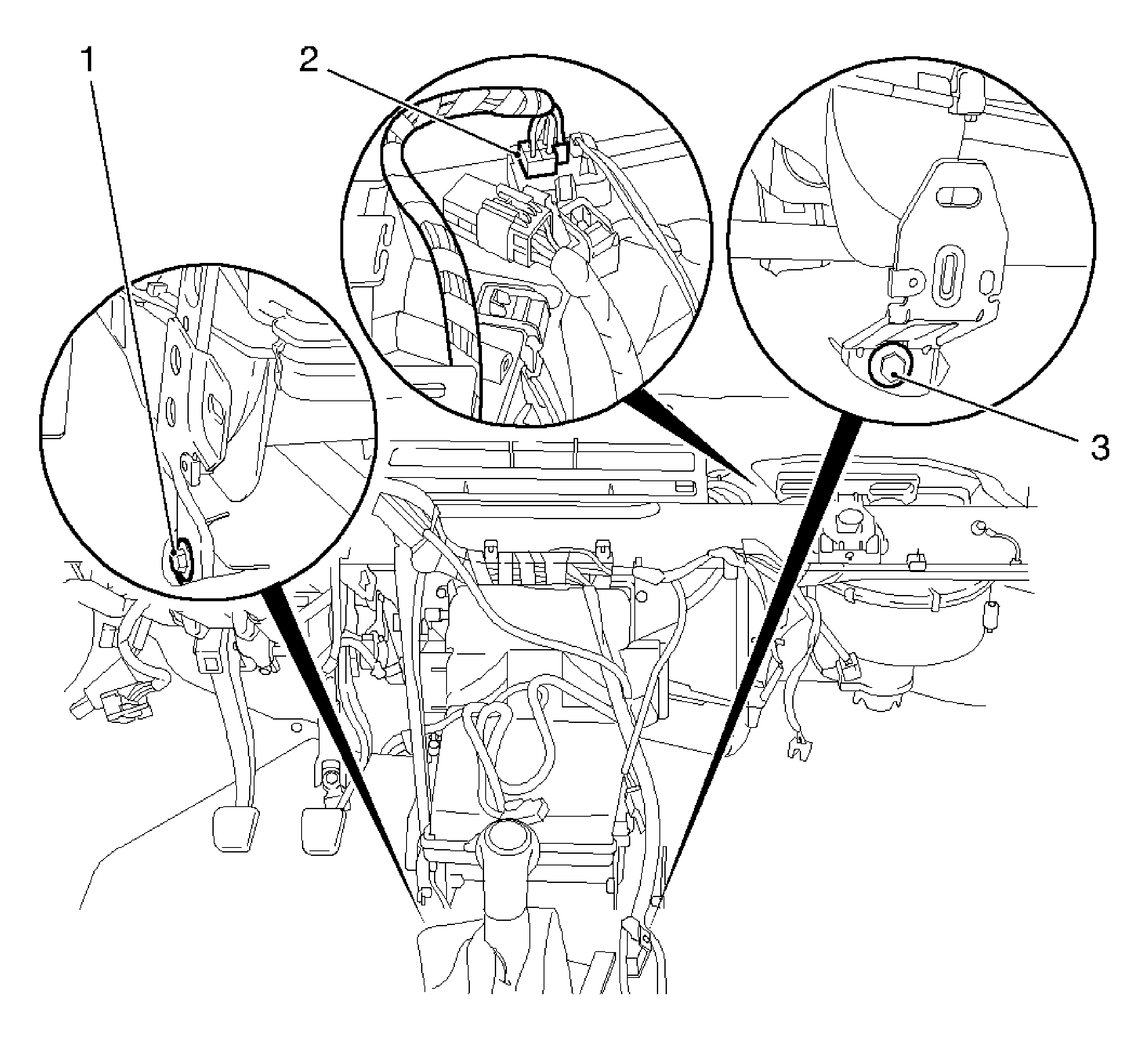
- Disconnect the wiring harness plug from the fan series resistor (2).
| • | Disconnect the wiring harness plug. |
| • | Release and disconnect the wiring harness plug. |
- Remove the front floor console bracket (1) and (3).
Remove the 2 bolts.
- Remove the I/P tie bar. Refer to
Instrument Panel Tie Bar Replacement
.
- Remove the HVAC module assembly.
Installation Procedure
- With the aid of an assistant, insert the HVAC module assembly.
Notice: Refer to Fastener Notice in the Preface section.
- Install the HVAC module assembly to the dash outside.
Tighten
Tighten the 8 bolts to 10 N·m (89 lb in).
- Install the I/P tie bar. Refer to
Instrument Panel Tie Bar Replacement
.
- Install the center I/P bracket.
Tighten
Tighten the 2 bolts to 13 N·m (113 lb in).
- Install the inflatable restraint I/P module. Refer to
Inflatable Restraint Instrument Panel Module Replacement
.

- Attach the coolant hoses to the heater core.
| 6.1. | Slide the 2 locks on the quick-release fittings in the arrow direction up to the stop. |
| 6.2. | The plastic rings (green) are covered. |
| 6.3. | Attach the 2 quick-release fittings on the heater core (1) connections up to the stop. |
| 6.4. | Slide 2 locks (3) on the quick-release fittings in the arrow direction up to the stop. |
Note the markings applied.
| 6.5. | The plastic rings (green) must be visible. |
| 6.6. | Inspect the correct seat of quick-release fittings and visibility of the plastic rings. |
- Install the air inlet screen.
| 7.1. | Install the windshield washer hose. |
| 7.2. | Install the 5 clips. |
Important: Ensure the screen wiper arms are correctly positioned.
- Install the windshield wiper arms.
| 8.1. | Attach the 2 wiper arms to shaft. |
| 8.2. | Install the 2 washers. |
Tighten
Tighten the 2 nuts to 17 N·m (13 lb ft).
| 8.3. | Install the 2 cover caps. |
- Install the air inlet screen.
- Install the I/P trim panel. Refer to
Instrument Panel Trim Panel Replacement
.
- Install the condensation drain.
Tighten
Tighten the 2 bolts to 5 N·m (44 lb in).
- For vehicles equipped with A/C, insert the retaining plate expansion valve.
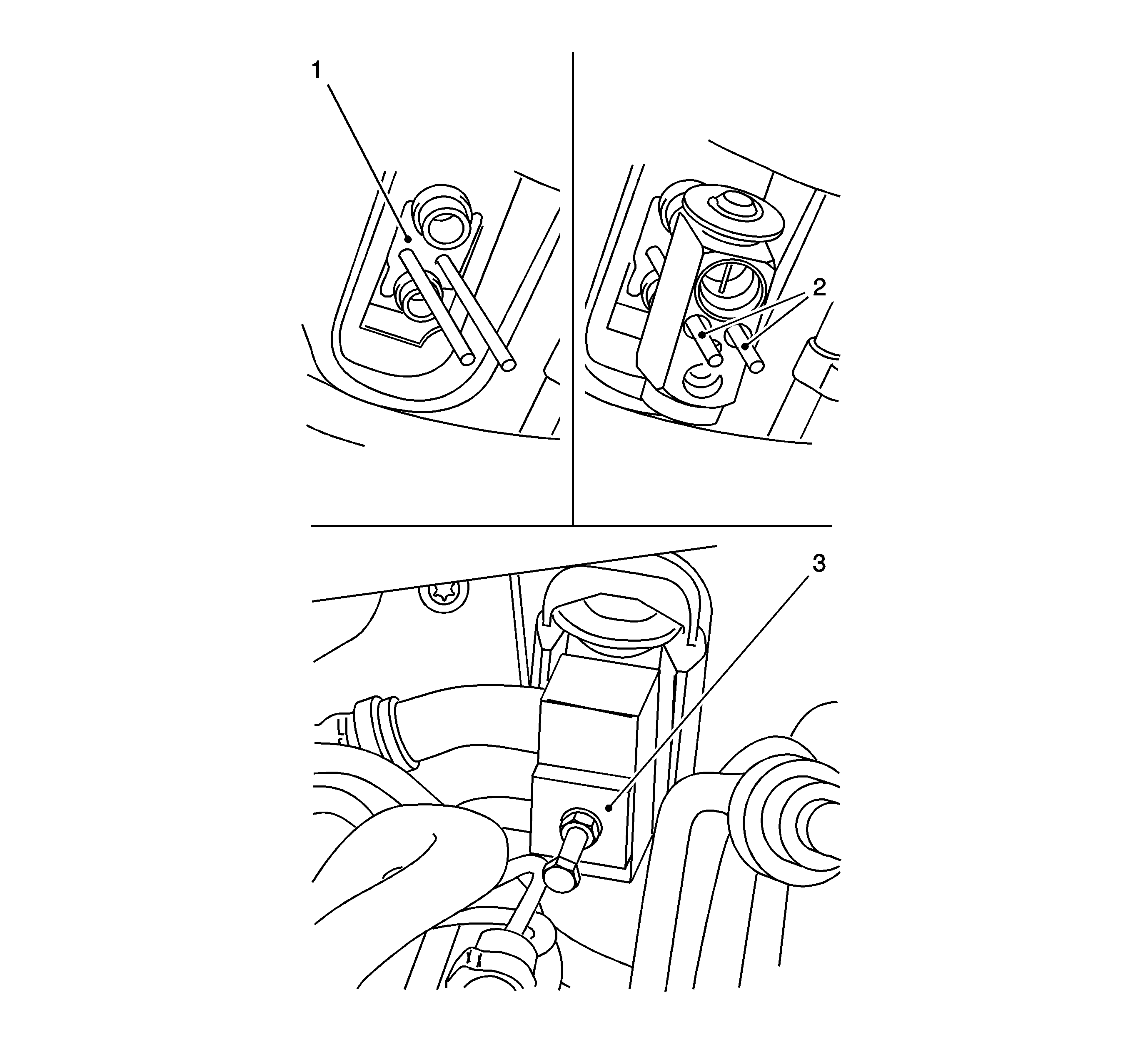
- For vehicles equipped with A/C, install the TXV.
| 13.1. | Use new sealing rings, before installation moisten only green colored sealing rings with mineral oil and insert. |
| 13.2. | Install the service threaded rods (2) into the retaining clip (1) to guide expansion valve. |
| 13.3. | Push the expansion valve onto service threaded rods until the refrigerant lines lie in the expansion valve. |
| 13.4. | Replace the threaded rods in succession with fixing bolts. |
Tighten
Tighten the expansion valve bolts to 6 N·m (19 lb ft).
- Attach the block connector.
Use new sealing rings, before installation moisten only green colored sealing rings with mineral oil and insert.
Tighten
Tighten the block connector bolt to 7 N·m (62 lb in).
- For vehicles equipped with A/C, recharge and top up the A/C system. Refer to
Refrigerant Recovery and Recharging
.
- Fill and bleed the cooling system. Refer to
Cooling System Draining and Filling
.
Important: Perform inspection for leaks with utmost care as hot coolant will escape into the driver footwell if there are leaks in coolant connections at the heater core.
- Inspect the coolant system for leaks. Refer to
Cooling System Leak Testing
.


